Amil 2000
DEUTSCHE NORM
Determining the rebound resilience of rubber using the Schob pendulum ICs 83.060
DIN -
53512
Supersedes December 1988 edition.
Prüfung von Kautschuk und Elastomeren - Bestimmung der Rückprall-Elastizität (Schob-Pendel)
In keeping with current practice in standards published by the International Organization for Standardization (ISO), a comma has been used throughout as the decimal marker.
Foreword This standard has been prepared by Technical Committee Prüfung physikalischer Eigenschaften von Kautschuk und Elastomeren of the Normenausschuss Materialprüfung (Materials Testing Standards Committee), and its specifications with regard t o the Schob pendulum correspond t o those in IS0 4662. IS0 4662 describes two pendulum designs, the Lüpke and the Schob pendulums. Extensive tests at national and international levels have shown that both designs yield similar results provided that the test piece thickness is increased from 6 mm to 12,5 mm for the Schob pendulum. It is important t o keep the friction of the pendulum low or to allow for correction with friction up to a particular degree. IS0 4662 permits the use of other designs if the apparent strain density lies within given tolerances, which are sufficiently great for both the Lüpke and Schob designs. The standard test temperatures (including tolerances) specified here are those specified in IS0 4662. Clause 3 includes reference to the relationship between rebound resilience and the loss factor, tan 6, which is particularly significant for the test piece thickness specified here (12,5 mm). However, when these parameters are compared, it should be taken into consideration that the loss factor is afunction of the temperature, frequency and amplitude of oscillation. Since amplitude and frequency are not exactly known, only a rough comparison can usually be made. Amendments This standard differs from the December 1988 edition in that use of a maximum pointer with the Schob pendulum has been omitted, and the standard has been editorially revised. Previous editions DIN 53512: 1940-12, 1959-01, 1965-12, 1976-07, 1981-03, 1988-12.
1 Scope The method specified here serves to determine the resilience of rubber having a Shore A or IRHD hardness of between 30 and 85 (see DIN 53519-1) when subjected t o impact. This method is particularly suitable for a rough assessment of the dynamic behaviour of rubber using simple equipment. When rubber is deformed, it absorbs energy which is partly recovered when it regains its original shape. Energy that is not returned as mechanical energy is dissipated as heat in the rubber.
2
Normative references
This standard incorporates, by dated or undated reference, provisions from other publications. These normative references are cited at the appropriate places in the text, and the titles of the publications are listed below. For dated references, subsequent amendments t o or revisions of any of these publications apply to this standard only when incorporated in it by amendment or revision. For undated references, the latest edition of the publication referred to applies.
Continued on pages 2 t o 5. Translation by DIN-Sprachendienst. In case of doubt, the German-language original should be consulted as the authoritative text.
No pari of this translation may be reproduced without the prior permission of V Deutsches Institut für Normung e. V., Berlin. Beuth Verlag GmbH, 10772 Berlin, Germany, s the exclusive right of sale for German Standards (DIN-Normen).
COPYRIGHT DIN DEUTSCHES Institut Fur Normung E.V.- English Licensed by Information Handling Services
Ref. No. DIN 53512 : 2000-0 English price group 05
Sales No. 0105 11.o0
Page 2 DIN 5351 2 : 2000-04 DIN 5351 3
Determination of viscoelastic properties of rubber under forced vibration beyond resonance Determination of indentation hardness (IRHD) of soft rubber using standard specimens DIN 5351 9-1 Rubber - Temperatures, humidities and times for conditioning and testing IS0 471 : 1995 IS0 4661 -1 : 1993 Vulcanized rubber and thermoplastics - Preparation of samples and test pieces
3
Concept
Rebound resilience Rebound resilience, R , is the ratio of energy returned t o energy applied. NOTE 1: In the test described here, the resilience is established as the ratio of the height of rebound of a pendulum by its height of fall. NOTE 2: For low values of loss factor, tan 6, the relationship between rebound resilience and this factor is expressed by R (1 - JG.tan 6) (see DIN 5351 3). NOTE 3: The rebound resilience for a given material is a function of: a) temperature, which critically affects resilience near the transition region of the material tested; b) the strain history of the material, which makes mechanical conditioning necessary, particularly in the case of filler-loaded rubber; c) design-related factors (e.g. type and dimensions of indentor and test piece, and the rate of strain and strain energy). Factors related t o time and strain amplitude have only moderate effects and fairly wide tolerances may be admissible for them.
-
4 4.1
Apparatus General
Rebound resilience shall be measured using a one-degree-of-freedom mechanical oscillatory device. Various types are available, all of which produce similar values for rebound resilience, provided their parameters lie within the limits specified in subclause 4.2.5.
4.2
Oscillatory device
The oscillatory device shall consist of a stand with an anvil, a test piece holder, a pendulum with an indentor and an indicating device. 4.2.1 FrameBtand and anvil The stand and anvil shall have a combined mass at least 1O0 times the impacting mass of the pendulum. 4.2.2 Test piece holder The test piece holder shall be designed t o ensure that the test piece is held firmly, without lateral restraint being required. Its grip shall be as effective as if the test piece were bonded t o the anvil. The difference in rebound resilience of a clamped and bonded test piece shall be less than two units. This condition shall be met for both highly resilient (rebound resilience around 90 YO) and very hard (Shore A or IRHD hardness of 80 t o 85) test pieces. The holder may be designed as a mechanical clamping device, a suction holder or as a combination of the two. 4.2.3 Pendulum The pendulum shall consist of an arm and a hammer incorporating an indentor with a hemispherical surface (see figure 1).The pendulum shall be suspended so that it oscillates circularly under the effect of gravity. It shall be possible to raise the hammerthrough an angle of 90" from its rest position. With the arm in the vertical position, the indentor shall just touch the test piece surface, the direction of impact of the indentor being perpendicular t o the test piece surface. 4.2.4 Indicator The indicator shall, as far as possible, provide for a friction-free measurement of the angle of rebound, a, from which the rebound resilience, R , is calculated as a percentage, using the following equation:
R = ( l -cosa).lOO See also clause 9. 4.2.5 Parameters The pendulum parameters shall be as follows: indentor diameter, D = 12,45 mm t o 15,05 mm; effective impacting mass, rn = 0,247 kg t o 0,35 kg;
COPYRIGHT DIN DEUTSCHES Institut Fur Normung E.V.- English Licensed by Information Handling Services
(11
Page 3 DIN 5351 2 : 2000-04 Pendulum length, L
-',
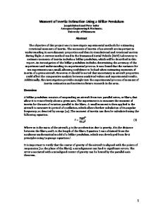
Figure 1: Principle of test apparatus
impact velocity, v = 1,4m/s to 2,04m/s; apparent strain energy density = m . $ / ( D . d2): (351
Tl;2)
kJ/m3
The Schob design has the following parameters: diameter, D = (15,OOI 0 , 0 5 ) mm; impacting mass, m = (0,255I0,003)kg; pendulum length, L = (200I 0 , 5 ) mm. On the basis of these parameters and a standard test piece thickness of (12,5I0,5) mm, an apparent strain energy density of 427 kJ/m3 is obtained, the energy of the Schob pendulum, A,, being equal to (500 I9)mJ. See subclause 5.4for the permissible friction of the apparatus.
5
Checking the apparatus
The following points are particularly relevant in the case of the Schob pendulum.
5.1
Force acting on the pendulum
In order to check the mass effective at impact on the test piece, m ,force F acting on the pendulum in the horizontal position at distance L from its pivot (see figure 1)shall be measured. This force shall be (2,50I0,03)N (2).
5.2
Reduced pendulum length
The reduced pendulum length, Lred,shall be determined from the oscillation period, T , as follows:
where g = 9,807m/s. It shall be (200Il 3)mm (4). The mean value of T shall be determined as an average from 50 oscillations, with the apparatus placed at an angle of 45",and the pendulum set in motion with an initial deflection of 5". From the mass and the reduced length, the energy of the pendulum, A,, is to be calculated using the following equation:
A N = m ' g ' Lred = m ' V2/2 It shall be (500 I9) mJ (6).
COPYRIGHT DIN DEUTSCHES Institut Fur Normung E.V.- English Licensed by Information Handling Services
(5)
Page 4 DIN 5351 2 : 2000-04
5.3 Impact velocity The impact velocity, Y,is t o be calculated from Lredusing the following equation:
-4
Y =
(7)
It shall be (1,98I0,Ol)m/s (8)
5.4
Friction
5.4.1 Test set-up An arrangement similar t o that described in subclause 5.2,permitting angles of impact up to 40" and allowing observation of the rebound angle, shall be used t o check for frictional losses.
5.4.2 Checking pendulum bearing friction and air friction In order t o check the pendulum bearing friction and air friction, the pendulum shall be deflected by about 40" and released. The number of full oscillations until the pendulum stops shall be counted, and shall be greater than 300. 5.4.3 Error of the indicated rebound resilience The error of the indicated rebound resilience shall be determined in five stages, at about 1 O YO, 20 YO, 30 YO, 50 YOor 60 YO, and 80 YOof the test scale. The pendulum shall be raised and supported or fixed. The angle of impact, a, shall then be measured using a cathetometer or a spirit level. Uncertainty of measurement shall not be greater than I0,065". The theoretical rebound resilience, R,, is t o be calculated, as a percentage, using the following equation:
R , = (1 - cos a ) . 1 O0
(9)
where a is the angle of rebound, in degrees. The indicator error is given by R - R , , where R is the rebound resilience indicated by the apparatus. The permissible error shall be I0,5YO.
6 Test pieces 6.1 Test piece preparation Test pieces having a thickness of (12,5I0,5)mm and a diameter of 29 mm t o 53 mm shall be used. They shall be prepared by moulding or cutting and shall have smooth and parallel surfaces. If the surface t o be impacted is tacky, it shall be dusted with talcum. If test pieces of the specified thickness are not available (e.g. where they are cut from finished parts), a stack of no more than three sheets of the same material may be used, provided the sheets have parallel surfaces and the same thickness throughout. Test pieces shall not contain textile or other reinforcing material. If the surface is not uniformly smooth, it shall be ground as specified in IS0 4661 -1. NOTE: In the case of thin test pieces, test piece deformation may be influenced by the rigidity of the anvil. An international interlaboratory test using test pieces 6 mm and 12 mm thick produced differences of 2 YOto 6 YOin the resilience values, such differences being a function of the hardness of the rubber, and reaching a maximum for very soft rubber.
6.2 Number of test pieces At least two pieces shall be tested.
6.3 Conditioning of test pieces Testing shall be carried out not earlier than 16 hours and not later than four weeks after vulcanization. At least during the last three hours of this period, the test pieces shall be conditioned at a temperature of (2312)"C. In the case of finished parts, the interval between vulcanization and testing should not exceed three months; otherwise, testing shall commence not later than two months after delivery to the customer.
7 Test temperature Testing shall normally be carried out at a temperature of (23I1)"C,although test temperatures of - 70 "C, - 55 "C,- 40 "C,- 25 "C,- 1 O "C,O "C,40 "C,55 "C,70 "C,85 "C and 1 O0 " C are also acceptable. For testing, test piece, anvil and test piece holder shall be brought to the test temperature, I1 "C, o r I 2 " C if test temperatures are below O " C (see DIN IS0 471).
COPYRIGHT DIN DEUTSCHES Institut Fur Normung E.V.- English Licensed by Information Handling Services
Page 5 DIN 5351 2 : 2000-04 The conditioning period is afunction of the characteristics of the conditioning device and whether the test piece is made up of a stack of sheets. The period required for test pieces 12,5 mm thick and a test temperature of 1O0 "C shall normally be 40 minutes. If the test pieces and the test apparatus are brought t o test temperature separately, the test pieces, after they are fitted into the holder, shall be allowed a further conditioning period of three minutes before testing commences. At low test temperatures, measures shall be taken t o prevent frost forming on the test pieces. If the entire apparatus is placed in a conditioning chamber for testing, friction shall remain within the limits specified in this standard.
8 Procedure After the test piece has been placed in the holder and conditioning has been completed, the pendulum shall be allowed t o fall from the horizontal position six times to strike the same point on the test piece, and shall be caught each time before it impacts again. The first three impacts serve to mechanically condition the test piece and the last three t o establish its rebound resilience. The median of the last three readings shall be determined (see DIN 53598-1).
9
Evaluation
The rebound resilience, R , as a percentage, is given by the following equation:
where h, is the rebound height; ho is the height of fall. The arithmetic mean of the rebound resilience shall be calculated from the medians for at least two test pieces, determined from the three values read off as percentages t o the nearest integer.
10 Test report The test report shall refer to this standard and provide the following information: a) type and designation of test pieces; b) conditioning of test pieces; c) number of test pieces; d) thickness of test pieces, in mm; e) history of test pieces (e.g. vulcanization conditions); f) conditioning period, in minutes, and temperature, in "C; g) test temperature, in "C; h) test apparatus and type of test piece holder; i) rebound resilience, R , as a percentage (arithmetic mean value); j) any deviation from this standard; k) date of testing.
COPYRIGHT DIN DEUTSCHES Institut Fur Normung E.V.- English Licensed by Information Handling Services