WC3-01
Proceedings of the 2005 IEEE/ASME International Conference on Advanced Intelligent Mechatronics Monterey, California, USA, 24-28 July, 2005
Design of an Autonomous Amphibious Robot for Surf Zone Operation: Part I Mechanical Design for Multi-Mode Mobility Alexander S. Boxerbaum, Philip Werk, Roger D. Quinn, Ravi Vaidyanathan
Abstract – The capability of autonomous and semiautonomous platforms to function in the shallow water surf zone is critical for a wide range of military and civilian operations. Of particular importance is the ability to transition between locomotion modes in aquatic and terrestrial settings. The study of animal locomotion mechanisms can provide specific inspiration to address these demands. In this work, we summarize on-going efforts to create an autonomous, highly mobile amphibious robot. A water-resistant amphibious prototype design, based on the biologically-inspired Whegs™ platform, has been completed. Through extensive field-testing, mechanisms have been isolated to improve the implementation of the Whegs™ concept and make it more suited for amphibious operation. Specific design improvements include wheel-leg propellers enabling swimming locomotion, an active, compliant, water resistant, non-backdrivable body joint, and improved feet for advanced mobility. These design innovations will allow Whegs™ IV to navigate on rough terrain and underwater, and accomplish tasks with little or no low-level control, thus greatly simplifying autonomous control system implementation. Complementary work is presently underway for autonomous control. We believe these results will lay the foundation for the development of a generation of amphibious robots with an unprecedented versatility and mobility. Index terms – Biologically-inspired robotics, legged vehicles, multi mode mobility, amphibious operations, reduced actuation.
I. INTRODUCTION There has been significant interest in the development of robots capable of autonomous amphibious operation within turbulent ocean surf zones. Potential operations for such a robot include: mine clearing, terrain mapping, and scouting potential approach lanes for amphibious naval operations. Terrestrial and aquatic mobility, control, navigation, communication, obstacle avoidance, and sensor payload remain critical issues to be resolved for successful operation. While much recent work in this area has focused on construction of robots based on legged and/or crawling elements to address these issues [1][2][3], very significant benefits could be achieved through the development of mechanisms enabling multiple modes of mobility, in particular with relation to crawling and swimming
locomotion. One recent example of work towards this goal is the robot AQUA (based on the RHex robotic platform) that was designed to be capable of aquatic and terrestrial locomotion [4]. The current prototype requires appendages to be manually switched to transition from walking to swimming, but a flipper foot combination is in development to allow autonomous changeover between locomotion modes. To date, however, a rugged amphibious robot capable of multiple modes of locomotion has yet to be fully developed for operations such as mine detection and clearing. A. Terrestrial Locomotion Cockroaches have remarkable locomotion abilities that provide a wealth of inspiration for robot design. In studies of cockroach movement, we have noted the following locomotion principles: 1) A cockroach has six legs that support and move its body; 2) It typically walks and runs in a tripod gait wherein the front and rear legs on one side of the body move in phase with the middle leg on the other side; 3) Although the front legs swing head-high during normal walking so that many obstacles can be surmounted without significant gait change, the animal changes its gait when it encounters larger barriers; 4) The cockroach turns by generating asymmetrical motor activity in legs on either side of its body as they extend during stance [5]; 5) A cockroach enhances its climbing abilities by changing its body posture before and during a climb over an obstacle [6]; 6) It uses its middle legs to pitch its body up prior to climbing obstacles that are higher than its head, which enables its front legs to reach higher; 7) During a climb it uses its body flexion joints
Manuscript received May 19th, 2005. A. S. Boxerbaum, P. Werk, and R. D. Quinn are with the Biologically Inspired Robotics Laboratory, Department of Mechanical and Aerospace Engineering at Case Western Reserve University (Phone: 216-368-5629, email:
[email protected]). R. Vaidyanathan is with the Autonomous Robotics and Systems Laboratory, Department of Systems Engineering at the Naval Postgraduate School (email:
[email protected]).
0-7803-9046-6/05/$20.00 ©2005 IEEE.
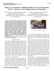
Fig. 1. Whegs™ II surmounts a 15 cm obstacle with the help of its body flexion joint.
1459
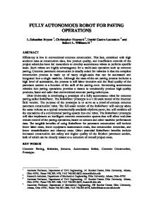
to bend the front half of its body down to avoid high centering. We have developed a series of rugged all-terrain robotic vehicles dubbed Whegs™ (Fig. 1) [7] capable of fast running and climbing through the incorporation of all of the aforementioned biologically-inspired mechanisms to navigate terrain. Common to all robots in this line is a single drive motor that powers six multi-spoke appendages called wheel-legs. When three-spoke wheel-legs are used, neighboring legs are offset by 60° yielding a nominal tripod gait. The spokes allow Whegs™ to climb over larger obstacles than a vehicle with similarly sized wheels. Whegs™ robots have compliant mechanisms in all six of their axles. These mechanisms allow them to passively adapt their tripod gait to irregular terrain. This compliance captures much of what the cockroach accomplishes with actions of its distal leg joints. Additionally, Whegs™ II (Fig. 1) incorporates a body flexion joint. This actively controlled joint enables it to perform both of the above body posture changes used by the cockroach, thereby improving its climbing ability. B. Amphibious Locomotion Amphibious robots typically rely on walking motion, where the robot is limited to the ocean floor. This greatly simplifies the design requirements, but limits the robot’s ability to navigate obstacles. Many animals that live in and out of water, such as salamanders, otters, frogs and penguins take advantage of the benefits of buoyancy by swimming with their legs and arms. A robot that can walk above and below water, as well as swim would have a new freedom to accomplish a myriad of tasks previously not possible. For this reason we are developing and testing a novel combination of a propeller and legs that will allow Whegs™ IV to swim as well as walk. The wheel-leg used in Whegs™ robots combines the superior mobility of a leg with the simplicity and controllability of a wheel. The Amphibious Whegs™ concept will extend the functionality of the Whegs™ platform by integrating the wheel-leg appendage
with the most common form of engineered water propulsion, the propeller (Fig. 2). The result is a propeller-leg that produces thrust parallel to its axis of rotation. C. Scope This paper proposes a novel design of an amphibious vehicle based on the Whegs™ platform. Several problems with previous Whegs™ are addressed in the new design, as well as new waterproofing requirements. The robot chassis is being built for autonomous testing on land, while parallel with this, several technologies are being developed to allow the robot to swim using modified Whegs™ appendages as propellers (propeller-legs). II. WHEGS™ IV Through extensive field-testing, we have isolated two primary ways to improve the implementation of the Whegs™ concept and make it more suited for autonomous operation. Previous Whegs™ robots have an open frame, where all components are attached to one of the cross members. This allows for a lightweight chassis that is easy to service, but debris can clog the drive train and water can damage the electronic components. Also, the body joint in Whegs™ II is backdrivable and motor current is continuously required to keep it from rotating. This is not power efficient. The body joint in Whegs™ III is not backdrivable, but had to be rebuilt frequently due to impact damage and fatigue. Whegs™ IV addresses these two problems with a novel partially passive body joint and a completely sealed body compartment. These innovations should make the robot more robust and well suited to autonomous operation over rugged terrain. III. COMPONENT LAYOUT Whegs™ IV is comprised of two body segments that are nearly symmetrical (Fig. 3). The front body segment will leave as much room as possible for sensors and related electronics. It will only contain the drive motor, steering
Fig. 2. Renderings showing Amphibious Whegs™ moving from water to land. It walks on the ocean floor, swims over large obstacles, and runs over rocks and onto the beach. It uses its body flexion joint to help control its pitch while swimming and to climb over obstacles on the ocean floor and on land.
1460
servos and a speed controller. In previous Whegs™ robots the compliant mechanisms were contained inside the frame. However, there is no need to waterproof these mechanisms so they have been moved outside the sealed frame to save space. All drive chains run along the sides to prevent dividing up the usable space. The front and rear bulkheads of the robot will be rounded to give good hydrodynamic characteristics and to allow it to push up and over irregularly shaped obstacles. Windows can be easily added to the bulkhead to allow for video cameras to be stored inside the front body segment. IV. SEALING THE BODY Whegs™ IV is completely encased, keeping dirt as well as water out. Both body segments are constructed from a ring of aluminum side panels with carbon fiber tops and bottoms. Each set of side panels is sealed to itself using a silicone gasket, while the carbon fiber panels are sealed to the side panels using rubber gaskets. This allows the robot to be easily serviced by removing the carbon fiber panels without breaking the seals between the side panels. Rotary axles must also penetrate the body of the robot in seven places, one for each wheel-leg and the body joint. Several rotary shaft seals are in consideration for this task.
Our first prototype will test urethane U-cup seals that use the outer ambient pressure to keep the seal against the shaft and housing. Other possibilities under consideration include mechanical seals or multiple o-rings. V. BODY JOINT Connecting the two body segments presents many problems. Torque must be transmitted from the front motor to the rear wheel-legs. Power and communication lines must be passed between the two body segments. The body joint must be actuated with a motor and any linkage must be water and dirt tight. A pair of coaxial shafts are used: the outer one is rigidly attached to the front body segment, allowing a motor in the rear body segment to actuate the body joint; the inner shaft is the middle wheel-leg drive shaft, which also passes torque to the rear of the robot. The outer shaft is 6.35 cm in diameter, large enough run several electrical lines through. By keeping all connections axial in nature, a standard rotary shaft seal around the outer shaft can be used to keep water and dust out (Fig 4). A body joint on previous Whegs™ allowed the robot to climb larger objects by giving the front wheel-legs higher reach and by preventing high centering. However, several designs have not survived field-testing. The first version of
Fig. 3. Cut-away rendering of component layout. The front compartment contains the drive motor, speed controller and steering servos. The remaining space is available for a PC board (shown), compass, GPS and other sensors (not shown). The rear compartment is shown with the body joint motor, speed controller, batteries and PIC controllers for the servos. The batteries can be placed anywhere in the robot for optimal balance.
1461
A prototype body joint has been built and tested. Using a 20 W motor and a 23:1 gear reduction, our calculations predicted a stall torque of 83.5 Nm and a slew rate of 56 deg/sec under a torque of 14.7 Nm. Experimentally, we were not able to find the stall torque because one of the two axial ball bearings that supported the Bellville springs failed while testing a load of 26.4 Nm. Resonant vibrations were observed, which may have contributed to the failure. Future work will include rebuilding the body joint with bushings instead of bearings and finding the stall torque and slew rate in order to find the efficiency of the system. With the exception of the bearing failure, the body joint performed as expected. The passive compliant range of motion of the Bellville springs was ±12 degrees, slightly less when tested with stiffer springs. The body joint could rotate over a full 360 degrees without variations in speed, and rotate continuously. Shaking the lever arm in all directions did not appear to affect the performance. Changing the Bellville springs was relatively easy and changed the stiffness of the lever arm as expected.
Fig. 4. Body flexion joint that can be water tight, compliant, actuated and allows cables to pass between the two body segments. Whegs™ with a body joint used a large backdrivable servo, but this solution results in constant current to maintain a particular body flexion angle, which is inefficient. To remedy this, Whegs™ III used a non-backdrivable worm gear. However, the transmission failed in fatigue because of the large impact loads it experiences in normal operation. It was clear that a new body joint actuator needed to be developed. The solution in Whegs™ IV is a compliant, nonbackdrivable body joint. Like the previous design, a motor with a transmission is connected to a worm that drives the worm gear. In this modified design, the worm can slide axially but not radially on the shaft and it is cushioned on both sides by Belleville springs. A large axial bolt holds the bearings in place and tensions the Bellville springs. When the front wheel-legs impact an obstacle, the front body segment rotates up and back, rotating the driven worm gear which pushes the driving worm in a fashion similar to a rack and pinion, allowing the Belleville springs to cushion the blow (Fig. 5). Regardless of the passive state of the body joint, the motor can actuate the body joint in either direction. This design essentially puts a spring in series with an actuator and is similar to a series elastic actuator used in several robotic applications [8]. Unlike a series elastic actuator, which is force controlled, this joint is partially passive, or independent of actuation. It is the same principle that Whegs™ uses to passively adapt its gait to the terrain. This non-backdrivable design is also inherently rotary, eliminating the need for cables. This design allows the passive stiffness of the body joint to be independently tuned in the clockwise and counterclockwise directions by changing the number and stiffness of the Belleville springs on either side of the worm. When run autonomously, it may be advantageous to have a very low stiffness body joint that works entirely passively to overcome obstacles. When in radio control mode, the body joint stiffness can be higher to allow more responsive user control.
1462
VI. Amphibious Whegs The Amphibious Whegs™ concept will extend the
Fig. 5. Demonstration of the passive compliance of the body flexion joint. In the top photo, the joint is loaded counterclockwise under 20 Nm. In the bottom photo, the joint is loaded clockwise under 14 Nm. The independently tuned Bellville springs on both sides of the worm give it this non-backdrivable compliance.
Fig. 6. Whegs™ IV will use two different steering methods for walking and swimming. The blue arrows show thrust created by the propellers in swimming mode, while the green arrows show the force acting on the ground in walking mode. In both cases, the red arrows indicate the resultant direction of the robot. functionality of the Whegs™ platform by integrating the wheel-leg appendage with the most common form of engineered water propulsion, the propeller. Four propellerlegs will then steer the robot in swim mode while the body flexion joint controls pitch (Figs. 2, 3). The middle wheellegs will spin in swim mode but will not have a propeller shape to produce thrust. Instead, a low-drag profile will be used to minimize interference with swimming operation. This design utilizes component redundancy of function to precipitate some key advantages. The wheel-legs will spin at the same velocity in all three operational modes. Therefore, a single motor and drive train will be able to power all six propeller-legs in all three modes of operation without a variable transmission. This allows for a single, more powerful, more efficient motor and less weight and complexity. However, unlike most ROVs that use fixed thrusters and variable thrust, all propeller-legs will have the same thrust. Instead, the robot will steer varying the direction of each thruster independently to achieve the desired motion (Fig. 6). With some modifications, the robot will also be able to use the same steering mechanisms for both walking and swimming. The body joint can be used to adjust pitch in order to dive and surface. The four horizontal thrusters will be at the farthest corners where they can provide the greatest moment about the center of mass, and in forward motion, the body of the robot will minimally interrupt the thrust flow. Because of this vectored thrust method of control, efficiency is dependent on having a wide range of motion for each propeller-leg. Several designs are under consideration that will allow the drive shaft to pivot 160
degrees while still transmitting torque to the propeller-legs. The robot will displace 13,600 cubic centimeters, or 13.9 kg of salt water. With sensors, the robot is expected to weigh between 14.5 and 15.5 Kg. A thin layer of urethane foam will be added to the top of the body as needed to give an overall neutral buoyancy. This will also place the center of buoyancy above the center of gravity, which limits undesired pitch and roll. The Wheg-Prop design consists of a ‘foot’ at the end of a propeller blade. The foot is shaped to have low drag during rotation, and may emulate the benefits of a cowling, which is typically used in low RPM, high thrust applications. On land, the foot will support the weight of the robot and prevent it from sinking into soft dirt or sand. The profile of the blade was determined by the desire to utilize the same power train for both land and water based propulsion. This placed limitations on the diameter, RPM, and available torque for the propeller. A full size wheg-prop will have a 30.5 cm diameter, spin at 100 RPM, and operate with an available torque of 1.24 Nm. A simple approximation of the drag of the robot during forward motion was calculated using the frontal cross-sectional area and a typical ROV drag coefficient, which showed a required net thrust of 1.32 N to travel at one body length per second. With these specifications in mind, we designed a preliminary blade profile and performed a blade element analysis of the propeller with no feet to find the thrusttorque relationship at 100 RPM. Variables such as the angle of attack and blade chord length were then adjusted to get the desired ratios. In the final design of the first propeller, the expected torque was 0.66 Nm and the expected thrust was 8.6 N for each propeller-leg at 100 RPM. This meets the design requirements of torque and velocity and gives a thrust of 34 N for the entire robot.
Fig. 7. Propeller-leg prototype design with support lattice from rapid prototyping.
1463
examine if we can make the feet sturdier and add traction elements while still retaining good propeller behavior. VII. CONCLUSIONS
Fig. 8. Test rig for half scale prototype propeller-leg. The motor and gearbox are freely suspended from a spring scale with a long shaft holding the propeller-leg. The RC controller varies speed, which is measured with a strobe light to the right. A Pro/Engineer model was made based on our analysis. The model was scaled to half size to fit in the available aquarium and then rapid prototyped using a Stratasys Dimension Fused Deposition Modeler. This machine produced a single piece propeller-leg prototype out of ABS plastic (Fig. 7). The half scale prototype was then tested in an aquarium using a motor from Whegs™. A vertically mounted spring scale was used to measure the thrust output and a strobe light was used to measure the rotational speed (Fig. 8). The prototype propeller-leg showed an output of 1.1 N of thrust at 118 rpm. This can be scaled up to approximately 8.90 N of thrust at 83 rpm for a full size propeller-leg. Due to motor limitations, the prototype could not be tested at a speed that would simulate the actual operating speed of 100 RPM. However, even at the lower speed, our results indicate a slightly greater than predicted force. We are examining several possibilities for this: the proximity of the propeller to the bottom of the tank may have caused a boundary effect, or the foot may have acted as a cowling, keeping the water on the blade longer and generating more force. In the near future, we will investigate these possibilities with a faster motor and a larger tank of water in order to eliminate boundary effects and allow us to more closely compare our observed and predicted values. Our preliminary results indicate that the feet at the end of the propeller blade do not significantly interfere with its function as a propeller. We have established a method of designing, prototyping and testing various propeller-leg designs with a very short turnaround and minimal cost. This ability is very important since we are designing a hybrid device that has to perform under two very different sets of requirements. In future experiments, we will use this method of prototyping to
We report the preliminary design of a robust amphibious biologically inspired robotic platform, Whegs™ IV. These design innovations will allow Whegs™ IV to navigate on rough terrain and under water, and to accomplish tasks with little or no low-level control. This will greatly simplify the autonomous control problem and give the vehicle unprecedented mobility and versatility. Because of Amphibious Whegs™ ability to swim, it could be deployed far out to sea, swim toward shore and then walk along the ocean floor through the surf zone and onto the beach. It could search for objects on land or on the ocean floor and swim over obstacles that pose any risk of trapping it, making it ideal for mine sweeping, surveying and civilian applications. Future work will focus on integrating this mobile robotic platform with sensors and autonomous control as well as further development of the propeller-leg design. VIII. REFERENCES [1] Bernstein, C., Connolly, M., Gavrilash, M., Kucik, D., Threatt, S., “Demonstration of Surf Zone Crawlers: Results from AUV Fest 01,” Surf Zone Crawler Group, Naval Surface Warfare Center, Panama City, FL, 2001. [2] Prahacs, C., Saunders, A., Smith, M., McMordie, D., Buehler, M., “Towards Legged Amphibious Mobile Robotics”, The Inaugural Canadian Design Engineering Network (CDEN) Design Conference, July, 2004. [3] iRobot Corporation, Ariel Robot, iRobot Corporation, “Ariel,” http://www.irobot.com/about/history.cfm, 2005. [4] Georgidas, C., German, A., Hogue, A., Liu, H., Prahacs, C., Ripsman, A., Sim, R., Torres, L.-A., Zhang, P., Buehler, M., Dudek, G., Jenkin, M. and Milios, E., “AQUA: An Aquatic Walking Robot,” Proc. UUVS 2004, Southampton, UK, 2004. [5] Ritzmann, R.E., Rice, C.M., Pollack, A.J., Ridgel, A.L. Kingsley, D.A. and Quinn, R.D, “Roles of descending control in locomotion through complex terrain,” Congress of Neuroethology, 2001, vol. 6, p. 234. [6] Watson, J.T., Ritzmann, R.E., Zill, S.N., Pollack, A.J. “Control of obstacle climbing in the cockroach, Blaberus discoidalis: I. Kinematics,” J. Comp. Physiology, 2002, vol. 188: 39–53. [7] Quinn, R.D., Kingsley, D.A., Offi, J.T. and Ritzmann, R.E., “Improved mobility through abstracted biological principles,” IEEE Int. Conf. On Intelligent Robots and Systems (IROS), Lausanne, Switzerland, 2002. [8] Robinson, D. W., Pratt, J. E., Paluska, D. J. & Pratt, G. A., “Series Elastic Actuator Development for a Biomimetic Robot,” IEEE/ASME International Conference on Advance Intelligent Mechantronics, 1999.
1464