Design of a belt actuator enhancing car occupant safety S.A.J. de Waal DCT 2008.053
Master’s thesis Coach(es):
ir. E.P. van der Laan dr.ir. P.C.J.N. Rosielle
Supervisor:
prof.dr.ir. M. Steinbuch
Technische Universiteit Eindhoven Department Mechanical Engineering Dynamics and Control Technology Group Eindhoven, April, 2008
Acknowledgements More than a year of working on the thesis, has made me an even more independent working person and made that I know better where my strengths and weaknesses are. First of all, I would like to thank my advisor Maarten Steinbuch who has given me the opportunity to work on this project. Also I would like to thank my coaches Nick Rosielle and Ewout van der Laan for the help during the process. Finally I would like to thank all people who are close to me for their support not only during the thesis, but also during my study period. Bas de Waal Eindhoven, April 16, 2008
i
ii
Contents 1
Introduction 1.1 General introduction . . . . . . . . . . 1.2 State of the art vehicle safety . . . . . . 1.3 Real-time controlled restraint systems 1.4 Problem statement and approach . . . 1.5 Outline of the research . . . . . . . . .
. . . . .
. . . . .
. . . . .
. . . . .
. . . . .
. . . . .
. . . . .
. . . . .
. . . . .
. . . . .
. . . . .
. . . . .
. . . . .
. . . . .
. . . . .
. . . . .
. . . . .
. . . . .
. . . . .
. . . . .
. . . . .
. . . . .
. . . . .
. . . . .
. . . . .
. . . . .
. . . . .
1 1 1 2 2 2
. . . . . .
. . . . . .
. . . . . .
. . . . . .
. . . . . .
. . . . . .
. . . . . .
. . . . . .
. . . . . .
. . . . . .
. . . . . .
. . . . . .
. . . . . .
. . . . . .
. . . . . .
. . . . . .
. . . . . .
. . . . . .
. . . . . .
. . . . . .
. . . . . .
. . . . . .
. . . . . .
. . . . . .
. . . . . .
. . . . . .
. . . . . .
5 5 6 8 10 10 11
Literature study 3.1 Introduction . . . . . . . . . . . . . . . . . 3.2 Actuator with deforming strip . . . . . . . . 3.3 Actuator with linear plastic deformation . . 3.4 Actuator with variable torque . . . . . . . . 3.5 Actuator with cutting device . . . . . . . . . 3.6 Actuator with brake and torsion bar . . . . . 3.7 Tension controllers . . . . . . . . . . . . . . 3.8 Belt pretensioner . . . . . . . . . . . . . . . 3.9 Automatic pretensioner . . . . . . . . . . . 3.10 Hydraulic cylinder . . . . . . . . . . . . . . 3.11 Electro-magnetic actuated hydraulic cylinder 3.12 Circular fluid cylinder . . . . . . . . . . . . 3.13 Conclusions . . . . . . . . . . . . . . . . .
. . . . . . . . . . . . .
. . . . . . . . . . . . .
. . . . . . . . . . . . .
. . . . . . . . . . . . .
. . . . . . . . . . . . .
. . . . . . . . . . . . .
. . . . . . . . . . . . .
. . . . . . . . . . . . .
. . . . . . . . . . . . .
. . . . . . . . . . . . .
. . . . . . . . . . . . .
. . . . . . . . . . . . .
. . . . . . . . . . . . .
. . . . . . . . . . . . .
. . . . . . . . . . . . .
. . . . . . . . . . . . .
. . . . . . . . . . . . .
. . . . . . . . . . . . .
. . . . . . . . . . . . .
. . . . . . . . . . . . .
. . . . . . . . . . . . .
. . . . . . . . . . . . .
. . . . . . . . . . . . .
. . . . . . . . . . . . .
13 13 13 14 14 14 14 16 16 16 17 17 17 17
4 Design explorations 4.1 Introduction . . . . . . . . . . . . . . . . . . . . . . . . 4.2 Concept designs . . . . . . . . . . . . . . . . . . . . . . 4.2.1 Solenoid . . . . . . . . . . . . . . . . . . . . . . 4.2.2 Movable chair . . . . . . . . . . . . . . . . . . . 4.2.3 Electric motor . . . . . . . . . . . . . . . . . . . 4.2.4 Gas driven cylinder . . . . . . . . . . . . . . . . 4.2.5 Gas driven cylinder with Electronic Wedge Brake 4.3 Concept design conclusions . . . . . . . . . . . . . . . . 4.4 Concept design discussion . . . . . . . . . . . . . . . . .
. . . . . . . . .
. . . . . . . . .
. . . . . . . . .
. . . . . . . . .
. . . . . . . . .
. . . . . . . . .
. . . . . . . . .
. . . . . . . . .
. . . . . . . . .
. . . . . . . . .
. . . . . . . . .
. . . . . . . . .
. . . . . . . . .
. . . . . . . . .
. . . . . . . . .
. . . . . . . . .
. . . . . . . . .
19 19 19 19 20 21 21 22 23 23
2 Actuator Requirements 2.1 Introduction . . . . 2.2 Simulation results . 2.3 Detailed description 2.4 Energy analysis . . . 2.5 Conclusions . . . . 2.6 Discussion . . . . . 3
. . . . . .
. . . . . .
. . . . . .
. . . . . .
. . . . . .
. . . . . .
. . . . . .
. . . . . .
. . . . . .
. . . . . .
iii
5
. . . . . . . . . . . . . . . . . .
. . . . . . . . . . . . . . . . . .
. . . . . . . . . . . . . . . . . .
. . . . . . . . . . . . . . . . . .
. . . . . . . . . . . . . . . . . .
. . . . . . . . . . . . . . . . . .
. . . . . . . . . . . . . . . . . .
. . . . . . . . . . . . . . . . . .
. . . . . . . . . . . . . . . . . .
. . . . . . . . . . . . . . . . . .
. . . . . . . . . . . . . . . . . .
. . . . . . . . . . . . . . . . . .
. . . . . . . . . . . . . . . . . .
. . . . . . . . . . . . . . . . . .
. . . . . . . . . . . . . . . . . .
. . . . . . . . . . . . . . . . . .
. . . . . . . . . . . . . . . . . .
. . . . . . . . . . . . . . . . . .
. . . . . . . . . . . . . . . . . .
. . . . . . . . . . . . . . . . . .
. . . . . . . . . . . . . . . . . .
. . . . . . . . . . . . . . . . . .
. . . . . . . . . . . . . . . . . .
. . . . . . . . . . . . . . . . . .
. . . . . . . . . . . . . . . . . .
. . . . . . . . . . . . . . . . . .
. . . . . . . . . . . . . . . . . .
25 25 25 25 25 26 26 28 29 29 31 32 32 32 33 33 33 38 38
6 Fluid-mechanical designs 6.1 Introduction . . . . . . . . . . . . . . . 6.2 Cylinder with EWB . . . . . . . . . . . . 6.3 Cylinder with linear piezo-electric brake 6.3.1 Piezo-electric actuator . . . . . . 6.3.2 Failsafe . . . . . . . . . . . . . . 6.4 Cylinder with energy absorbing strips . 6.4.1 Energy absorbing strip . . . . . 6.5 Pneumatic cylinder . . . . . . . . . . . . 6.5.1 Analytical gas flow description . 6.5.2 Gas inflator test . . . . . . . . . 6.5.3 Simulink model . . . . . . . . . 6.6 Hydraulic cylinder . . . . . . . . . . . . 6.6.1 Design description . . . . . . . . 6.6.2 Fluid flow control options . . . . 6.6.3 Unigraphics stress analysis . . . 6.7 Conclusions . . . . . . . . . . . . . . . 6.8 Discussion . . . . . . . . . . . . . . . .
. . . . . . . . . . . . . . . . .
. . . . . . . . . . . . . . . . .
. . . . . . . . . . . . . . . . .
. . . . . . . . . . . . . . . . .
. . . . . . . . . . . . . . . . .
. . . . . . . . . . . . . . . . .
. . . . . . . . . . . . . . . . .
. . . . . . . . . . . . . . . . .
. . . . . . . . . . . . . . . . .
. . . . . . . . . . . . . . . . .
. . . . . . . . . . . . . . . . .
. . . . . . . . . . . . . . . . .
. . . . . . . . . . . . . . . . .
. . . . . . . . . . . . . . . . .
. . . . . . . . . . . . . . . . .
. . . . . . . . . . . . . . . . .
. . . . . . . . . . . . . . . . .
. . . . . . . . . . . . . . . . .
. . . . . . . . . . . . . . . . .
. . . . . . . . . . . . . . . . .
. . . . . . . . . . . . . . . . .
. . . . . . . . . . . . . . . . .
. . . . . . . . . . . . . . . . .
. . . . . . . . . . . . . . . . .
. . . . . . . . . . . . . . . . .
. . . . . . . . . . . . . . . . .
39 39 39 40 40 41 41 42 43 44 45 45 51 51 53 55 56 56
Conclusions and Recommendations 7.1 Conclusions . . . . . . . . . . . . . . . . . . . . . . . . . . . . . . . . . . . . . . . . . 7.2 Recommendations . . . . . . . . . . . . . . . . . . . . . . . . . . . . . . . . . . . . . . 7.3 Future developments . . . . . . . . . . . . . . . . . . . . . . . . . . . . . . . . . . . . .
57 57 58 59
7
Electro-mechanical design 5.1 Introduction . . . . . . . . . . . . 5.2 Energy analysis summary . . . . . 5.3 Design . . . . . . . . . . . . . . . 5.4 Optimal gear ratio . . . . . . . . . 5.5 Initial inertias . . . . . . . . . . . 5.5.1 Load inertia . . . . . . . . 5.6 Gear selection . . . . . . . . . . . 5.6.1 Gear layout . . . . . . . . . 5.6.2 Gear strength . . . . . . . 5.6.3 Iterative selection of gears . 5.7 Choosing components . . . . . . . 5.7.1 Selecting bearings . . . . . 5.7.2 Mounting the gears . . . . 5.7.3 Unigraphics assembly . . . 5.7.4 Failsafe . . . . . . . . . . . 5.8 Performance . . . . . . . . . . . . 5.9 Conclusions . . . . . . . . . . . . 5.10 Discussion . . . . . . . . . . . . .
. . . . . . . . . . . . . . . . . .
. . . . . . . . . . . . . . . . . .
A Load axle stress calculations
61
B Fast pressure relieve options B.1 Two membranes . . . . . . . . . . . . . . . . . . . . . . . . . . . . . . . . . . . . . . . B.2 Explosive cord . . . . . . . . . . . . . . . . . . . . . . . . . . . . . . . . . . . . . . . . B.3 Glass bottom . . . . . . . . . . . . . . . . . . . . . . . . . . . . . . . . . . . . . . . . .
63 63 64 64
iv
Abstract From earlier studies it followed that restraint systems are capable of reducing injuries of car occupants significantly. An active restraint system is able to adapt the belt-force based on several parameters. These parameters include the vehicle (type, dimensions and mass), the occupant (mass, length, gender and age) and the severity of the crash (opponent and relative speed). A controller in the car calculates a reference belt-force profile based on the chest acceleration of the occupant. The goal of this thesis is to design a belt-force actuator which is able to apply a given force profile to the belt. In this thesis, multiple designs for an active belt restraint actuator in cars are proposed. Although real-time controlled restraint systems show promising results in simulation, state of the art restraint systems which are implemented in cars can still be regarded as passive restraint systems. That is, they are not able (or only in a very limited manner) to adapt the belt-force to the occupants, vehicle and crash. In order to design the actuator, it is important to know which requirements it has to fulfill. From research and simulations it followed that the most important requirements are put on force, derivative of force, displacement of the belt, bandwidth of the actuator. Next to that, some less important requirements are put on dimensions, weight, cost and the number of times the actuator should be used and the failsafe. In Chapter 1, a general introduction in automotive safety is given and the problem and objectives of this thesis are stated. In chapter 2, all requirements the actuator has to fulfill are stated. They partly follow from previous research, whereas other requirements follow from simulations. In these simulations, an actuator is placed in a closed loop. The properties of the actuator are altered and there is looked at what effect the actuator performance has on the chest acceleration of the occupant. In Chapter 3, a literature study is performed at state-of-the-art belt actuators. Most of these actuators are only one-way acting or partly adaptable. In Chapter 4, design explorations are done, from which two specific actuators are worked out into more detail in the following chapters. Two active belt restraint designs are proposed: the actuator driven by electric motors and a cylinder which is driven by a gas inflator. In Chapter 5, the electric motor design is worked out into more detail. Gears, bearings and support structures are designed and tested for strength in simulations. It follows that the electric motor design is capable of meeting the requirements as stated and shows very promising. In Chapter 6, the fluid-mechanical design is worked out into more detail. Several design directions are taken, but a cylinder for the pay-in as well as the pay-out of the cylinder chosen because of its straightforward design. Simulations show that a pneumatic cylinder is also capable of fulfilling the requirements as stated. Also, a fluid cylinder is proposed which is controlled by valves. It must be noted however that the valves are the bottleneck for both designs. As a conclusion one could say that two types of active restraint actuators are proposed which meet the requirements as stated. However, further research is needed in order to improve the reaction time of pneumatic as well as hydraulic valves.
v
vi
Samenvatting Uit eerder onderzoek is gebleken dat veiligheids-systemen in auto’s, zoals gordels, letsel van inzittenden significant verminderd. Een actief veiligheids-systeem past de gordelkracht aan waarbij rekening wordt gehouden met verschillende parameters. Deze parameters omvatten het voertuig (type, afmetingen en massa), de inzittende (massa, lengte, geslacht en leeftijd) en de hevigheid van de botsing (de opponent en relatieve snelheid). Een regelaar in de auto berekent een gordelkracht referentie profiel welke is gebaseerd op de borstversnelling van de inzittende. Het doel van deze thesis is een gordelkrachtactuator te ontwerpen welke een voorgeschreven krachtprofiel kan leveren. Om dit te bereiken zijn verschillende actieve gordelsysteemactuator ontwerpen voorgesteld. Hoewel "real-time" geregelde veiligheids-systemen goede resultaten behalen in simulaties, kunnen alle "state of the art" veiligheids-systemen nog steeds als passief worden beschouwd. Dit betekent dat deze systemen de gordelkracht (bijna) niet aanpassen aan de inzittende, het voertuig of de botsing. Om de actuator te kunnen ontwerpen moeten een pakket van eisen opgesteld worden. Uit onderzoek en simulaties volgt dat de belangrijkste eisen de kracht, de afgeleide van de kracht, de verplaatsing van de riem en de bandbreedte van de actuator omvatten. Tevens worden er eisen gesteld aan de afmetingen van de actuator, de massa van de actuator, de totale kosten, het aantal keren dat de actuator moet kunnen worden gebruikt en de failsafe. In hoofdstuk 1 wordt een algemene introductie in voertuig-veiligheid gegeven. Daarnaast wordt de probleemstelling geponeerd en de doelen van de thesis verhelderd. In hoofdstuk 2 worden alle eisen waaraan de actuator dient te voldoen besproken. Deze eisen volgen deels uit eerder onderzoek, maar ook uit eigen simulaties. In deze simulaties wordt de actuator in een gesloten lus geplaatst, waarbij de eigenschappen van de actuator steeds worden aangepast. Hiermee wordt zichtbaar gemaakt wat deze aanpassingen voor effect hebben op de borstversnelling van de inzittende. In hoofdstuk 3 worden "state of the art" actuatoren besproken waarover reeds gepubliceerd is. Het merendeel van deze actuatoren werkt slechts in 1 richting of heeft een beperkt adaptief vermogen. In hoofdstuk 4 zijn verkenningen uitgevoerd m.b.t. het ontwerp. Hieruit zijn twee typen actuatoren naar voren gekomen: 1 type maakt gebruik van electro-mechanische componenten, waarbij het 2e type gebruik maakt van vloeistof-mechanica, welke wordt aangedreven door een airbag gaspatroon. In hoofdstuk 5 wordt de elektro-mechanische actuator uitgewerkt. Hierin worden de mechanische delen, zoals tandwielen, lagers en het frame geselecteerd en doorgerekend. Hieruit volgt dat dit concept aan de gestelde eisen voldoet. In hoofdstuk 6 is de vloeistof-mechanische actuator uitgewerkt. Verschillende ontwerpen worden besproken, waaruit een cylinder welke het innemen en uitgeven van de cylinder verzorgt is gekozen vanwege zijn eenvoud. Uit simulaties volgt dat een pneumatische cylinder aan de gestelde eisen voldoet wanneer de klepdynamica wordt verwaarloosd. Daarnaast is een vloeistofmechanische cylinder uitgewerkt welke door kleppen wordt bediend. Voor beide ontwerpen zijn deze kleppen de beperkende factor. Concluderend zijn er twee typen actieve veiligheidsactuatoren ontworpen welke beide aan de eisen voldoen. Er is echter nog vervolgonderzoek nodig om de responsie van de pneumatische- en hydraulische kleppen te verbeteren.
vii
viii
List of symbols
f1 t P Fi F˙i v E ω Ti x ~B µ0 I ~l N φ Ji ri iop D di L W H
bandwidth time power force of member i derivative of force velocity energy rotational velocity torque of member i displacement or cutting depth magnetic field permeability of vacuum current part of current carrying wire number of turns of wire flux or angle rotation inertia of i radius of i optimal gear ratio rr12 diameter diameter of part i length width height
ρ ai mi α m p zmin hf x hf B νi Ei σy st Pd Y fo γ µij θ¨ pi Ai cqi Nb
density acceleration of i mass of i pressure angle module pitch = πm minimal number of teeth tooth height height of dedendum 1.25m contact band width poisson ratio of material i modulus of elasticity of material i yield stress of material i bending stress transverse diametrical pitch dimensionless tooth factor overload factor safety factor coefficient of friction between materials i and j angular acceleration pressure in chamber i surface of area i flow characteristic constant of valve i number of bolts ix
[Hz] [ms] or [s] [kW] [N] � [kN] � or N ms m [s]
or�[kJ] � �[J]rad � or krad s s [N] [m] [T] �H � 4π10−7 m [A] [m] [-] [V � · s]2 or � [deg] kgm [m] [-] [mm] or [m] [mm] or [m] [mm] or [m] [mm] or [m] h[mm]i or [m] kg
3
m� �m s2
[kg] [deg] [mm] [mm] [-] [mm] [mm] [m] [-] [GPa] [MPa] [MPa] � � mm−1 [-] [-] [-] [-] � � rad s2
[bar] or [Pa] [m2 ] [-] [-]
mi Vi Ti dc
mass of gas in chamber i volume of chamber i temperature of gas in chamber i cylinder damping
R γ Ngi
ideal gas constant = 296.8 polytropic gas constant = 1.4 number of gas inflators
m˙ i V˙i ˆr r Le Re τ φ¨ x ¨
change in mass in chamber i change in volume unit vector pointing from source point to field point displacement vector electric inductance electric resistance time constant angular acceleration of belt actuator acceleration
x
�[kg]3 � m [K] � � Ns
hm i J kgK
[-] h[-] i kg
� Ls� s
[-] [m] [H] [Ω] �[ms] � rad
s2� �m s2
Chapter 1
Introduction 1.1
General introduction
Transport plays a very important role in our lives. In a period of about 100 years, more and more people have been given the opportunity to go from one place to another. Especially with upcoming economies such as China or India, the phenomenon "mass transportation" will get even more massive. Although mass transportation comes hand in hand with more wealth and freedom, it also has some drawbacks. First of all, most ways of modern transportation are quite polluting. International politics are reacting upon this trend by e.g. the Kyoto treaty. Furthermore, because so many people are involved in mass transportation such as a cars, there are a large numbers of fatalities. Apart from that, even more people get injured. World-wide 1 million people are killed in road traffic accidents every year. In Europe alone, traffic accidents result in 40,000 fatalities and 500,000 hospital admissions a year. This also comes with additional costs of 70 billion Euros [32].
1.2
State of the art vehicle safety
The high numbers of fatalities and injuries resulting from transportation by car are despite the fact that cars become more and more safe. The safety measures which are taken to protect the occupants are divided in a classical manner in two classes, being; • Passive safety: All measures taken, reducing the risk of fatalities or injuries from a crash • Active safety: All measures taken, reducing the probability of being involved in a crash Passive safety measures which can be thought of reduce the risk of fatalities or injuries when a crash is unavoidable. This item can again be subdivided in three groups. The first of all is the control of the occupant motion. This motion is restrained by a seatbelt, airbag and in some vehicles by active headrests and pretensioners. The crashworthiness of cars can be mentioned as the second group of measures. The crashworthiness is mostly defined by the crumple zone of the car. Also, compatibility comes into play, that is compatibility with other cars, as well as objects such as buildings. The third group of measures is the reduction of fatalities due to so-called "secondary" collisions of the occupant with the interior of the car. To reduce injuries, padding is added and sharp edges are avoided. Next to the passive safety measures, another type of safety measure can be taken, being the so-called active safety. Active safety comprises all measures taken to avoid a crash. This field of research is not yet fully exploited, especially from a car point of view. From a cars point of view, the state of the art in active safety measures can be mainly seen from Volvo [5], Audi, Mercedes [4] and Lexus. These manufacturers provide e.g. the Blind Spot Information System (or BLIS), which warns the driver for a car in the blind spot. In this way, collisions can be avoided when otherwise the driver would have changed lanes. Another way of providing more active safety is to monitor the driver himself. This is partly done by checking whether there is any alcohol (or in the near future drugs) in his blood. Next to 1
that, the driver’s activity is monitored by cameras in order to make sure the driver does not fall asleep. Also, the higher positioned cars are fitted with systems which can detect a potential crash and take measures to avoid such a crash such as the 2nd generation of Pre-Safe. The road ahead is scanned by radar. When the relative speed in between the car in front and the driver’s car is too large, it is possible to let the car brake automatically. Next to that, the driver is warned for a possible occurring crash. Although these measures make cars safer and safer, it is believed that the injury level can be reduced even further. In order to do so, real-time controlled restraint systems are introduced.
1.3
Real-time controlled restraint systems
When an actuator is referred to as "real-time controlled", it is meant that the occupant responses can be influenced during the crash based on measurements in order to reduce injuries significantly. Injury criteria are for example defined by the chest acceleration, chest deflection and neck flexion, although in this thesis only the chest acceleration is taken into account. The measurements apply to the occupant (mass, length, gender and age), vehicle (type, dimensions and mass) and severity of the crash (opponent and relative speed). From this information, a reference force or reference displacement profile is calculated. In this thesis there is looked at manipulating the chest acceleration by controlling the belt-force. In controlled restraint systems, a restraint actuator will be essential.
1.4
Problem statement and approach
In the work of [17] and [40], the focus lies on belt actuators, where the belt-force is manipulated. Since this type of actuators do not exist, the objective of the research is to design such an actuator. The goal of such an actuator is to reduce injuries of vehicle occupants. A couple of design criteria have to be answered or defined, such as: • design concept (manipulation of force or position) • actuator specifications (bandwidth, maximum force, displacement, accuracy) • force element • actuator compatibility (dimensions, auxiliaries, weight) • general issues (failsafe, costs, implementability)
1.5
Outline of the research
The goal of this research is to design an active actuator which is capable of reducing injuries of occupants in vehicles. This is done by manipulating the chest acceleration by controlling the belt-force or belt-displacement during the crash. Also, the actuator is able to adjust to vehicle properties, occupant and crash information. In this research, several subjects are discussed. In chapter 1, "Introduction", public transport is discussed in general. Next to that, state-of-the-art restraint systems are discussed. Also, the problem statement is presented. Finally, the outline of the report is discussed. After the introduction, it is important to know the requirements the actuator has to fulfill. In chapter 2, "Actuator requirements", those requirements are specified. For that, the response of a Hybrid III dummy is looked at when it is subject to a typical crash pulse. From information about the belt-force and belt displacement, powers and energies needed to provide the force and displacement are calculated. Also, some simulations are performed wherein the performance of the actuator is cut. From this, minimum requirements concerning e.g. maximum force can be derived. In chapter 3, "Literature study", a thorough literature study is performed at patents on restraint systems. It turns out that most of the state-of-the-art restraint systems are passive. Also, there is looked at what is already available in cars on the road. From this, a good overview of present restraint actuators is available, which makes it 2
easier to build upon. In chapter 4, "Design explorations", basic designs are discussed and examined when keeping the requirements in mind . From this comparison, a design direction follows, upon which the electric motor - and cylinder final designs are based. After this design exploration chapter, two different designs show promising to work out into more detail. This is done in chapters 5 and 6. In chapter 5, "Electro-mechanical design", the first final design is discussed. It consists of three electric motors which drive a load by gears. Also, the design proces is discussed, from choosing the motor, the gears ratio, up to the gear materials. In chapter 6, "Fluid-mechanical design", the second final design is discussed. There is looked at a second final design because the latter seems more promising when there is looked at the performance, but is more difficult to manufacture. Also, the design proces is discussed. The final cylinder design consists of a gas inflator which drives a fluid. This fluid presses against a piston onto which the belt is connected. Conclusions are drawn in chapter 7, "Conclusions and recommendations". Also, some recommendations are done in order to serve any future research on this topic.
3
4
Chapter 2
Actuator Requirements 2.1
Introduction
In this chapter an analysis of the belt actuator is made in order to estimate the energy and power needed to actuate the belt. At the same time, the actuator has to fulfil some criteria as well as some requirements, as mentioned below: • Feasibility: there is looked at the possibility of actually producing the proposed actuator. Therefore, state of the art technologies as well as of-the-shelf parts are used as a guide. • Controllability: the criterion accounts for the possibility to control the behavior of the actuator. This concerns movable mass (e.g. in a mechanical way), but also controllability from a control point of view such as bandwidth. • Storage space: this criterion deals with the space which is required in order to equip the car with one actuator. With that, the actuator itself, electronics, auxiliaries and any shielding is accounted for. • Compatibility: this describes a more overall criterion, keeping space- as well as e.g. magnetic shielding in mind. The question to be answered is "how much of the car is to be altered in order to install the actuator". • Failsafe: this describes the failsafe behavior when any electronics should fail. The safety of the occupant should be equal to the safety provided when using an "ordinary" belt-force restriction. • Weight: this criterion encapsulates all the components which add weight to the car by installing the actuator. One can think of the actuator itself, electronics, auxiliaries and/or shielding. Furthermore, the actuator has to fulfil some requirements, being: • the accuracy has be better than 0.5 kN • the maximum stroke has to be at least 400 mm • the actuator has to be made at the lowest cost possible • the actuator has only to be used once • the actuator has to be as small as possible The accuracy of the actuator has to be better than 0.5 kN because otherwise the occupant would feel too large changes in force on the body. The maximum stroke follows from the displacement of the belt in closed-loop simulations as can also be seen in figure 2.6(b). The belt-force is restricted by requirements which are, amongst others, determined from closed loop simulations of a model of 5
beltforce 1 s
1
force
error
Integrator aref
controller achest Selector
Madymo model Selector 1
0
xbelt
t
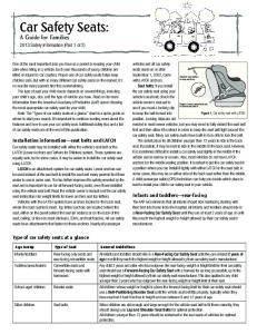
Figure 2.1: Simulinkmodel used in actuator simulation
the occupant. This MADYMO model of a 50-percentile male Hybrid III dummy [40] is subject to a belt-force exerted by the actuator. MADYMO is a multi-body-dynamics program in which the dummy is modeled as masses which are connected by joints, springs and dampers. The belt-force is used to control the chest acceleration of the dummy by applying feedback. This chest acceleration has to follow a reference profile as determined from [40]. A controller calculates the optimal belt-force for a given crash pulse, in order to follow the acceleration reference profile. The belt-force is dependent on the occupant, vehicle and crash severity, but the acceleration reference profile is a "baseline". Even with a heavy 95 percentile person, the belt-force does not exceed 10 kN. The Simulink scheme of the closed-loop model can be seen in figure 2.1.
2.2
Simulation results
Three different simulations are performed in which the belt-force is limited. First of all, the largest force which can be exerted by the actuator is limited to different values. The effects of the maximum belt-force on the acceleration of the chest can be seen in figure 2.2. From this figure it becomes clear that limiting the belt-force under 9 kN affects the chest acceleration. Then, the controller is not able to follow the reference signal in force, which results in an error between both reference - and actual chest acceleration. The error in chest acceleration becomes larger than 10 percent which is unacceptable. Since simulations on a 95 percentile dummy show that a force of at least 10 kN is needed, the minimum allowed belt-force should still be at least 10 kN. In a second simulation, the rate at which the belt-force is allowed to change is varied. The effects of these variations on the acceleration of the chest can be seen in figure 2.3. From this figure, one can see that N a maximal derivative in force of 500 ms influences the ability to follow the reference chest acceleration. N is taken as a limiting value, The deviation in acceleration from the reference curve where 2000 ms N exceeds 10 percent which is unacceptable. When a maximal derivative in force of 750 ms is taken, the force does not follow the reference curve exactly, but deviations in chest acceleration are minimum. N Therefore, a minimum derivative in belt-force of 750 ms is taken as a bound. In the third simulation, the bandwidth of the actuator is varied. To achieve this, the force signal is led through a 1st order low-pass filter. The results of this filtering can be seen in figure 2.4. The bandwidths vary from f1 equal to 100 Hz up to 500 Hz. As can be seen from this figure, filtering the actuator force has a large influence on the ability to follow the reference signal. Because next to the filter, the controller has to be altered too, the performance degrades. Since this is only an evaluation, a more advanced controller, like a robust controller, is not looked at. One can see that the performance of the actuator when a cut-off frequency of 100 Hz is taken is very poor. The deviation from the (almost normal) signal with a bandwidth of 500 Hz is about 100 sm2 . However, when increasing the bandwidth to 200 Hz, the deviation becomes much smaller and even acceptable. Therefore, a bandwidth of the actuator of at least 200 Hz is required. 6
beltforce [kN]
0 −1 −2 −3 −4 −5 −6 −7 −8 −9 −10 0
sat = inf −11 −10 −9 −8 20
40
60
80 time [ms]
100
120
140
160
chest acceleration [m/s2]
50 0 −50 −100 −150
sat = inf −11 −10 −9 −8
−200 −250 −300 0
20
40
60
80 time [ms]
100
120
140
160
Figure 2.2: influence of saturated belt-force on chest acceleration
0 −1 beltforce [kN]
−2 −3 −4 −5
dF/dt = 500 750 1000 1500 2000
−6 −7 −8 −9 0
20
40
60
80 time [ms]
100
120
140
160
chest acceleration [m/s2]
50 0 −50 −100 −150
dF/dt = 500 750 1000 1500 2000
−200 −250 −300 0
20
40
60
80 time [ms]
100
120
˙ on chest acceleration Figure 2.3: influence of max |F (t)|
7
140
160
beltforce [kN]
0 −1 −2 −3 −4 −5 −6 −7 −8 −9 −10 0
f1 = 500 400 300 200 100 20
40
60
80 time [ms]
100
120
140
160
chest acceleration [m/s2]
50 0 −50 −100 −150 f1 = 500 400 300 200 100
−200 −250 −300 −350 0
20
40
60
80 time [ms]
100
120
140
160
Figure 2.4: influence of low-pass filtered force on chest acceleration
2.3
Detailed description
Here, the force and displacement reference profiles will be looked at into more detail. In figure 2.5(a) one can see the belt-force. The figure is split up in a couple of time periods. In period 1, there is pulled at the belt. Pulling at the belt is needed, partly because any slack is to be removed and partly to handle strain of the belt. Also, the occupant is pulled into its seat in order to provide about 50 mm extra crash travel. In periods 2 and 3, the value of the belt-force is clipped because it is believed that a force of 10 kN is sufficient in order to safely counteract the movement of the occupant as is already shown from simulation. In periods 4 and 5, the force is reduced. This sudden change in period 4 is mainly caused by the change in sign of the velocity as a result of which the friction of the so called D-ring is felt. In period 6, the force builds up again, because the occupant is too close to the steering wheel and a collision with it is to be avoided. In period 7, the crash is almost at its end and the restraining force can be reduced to zero. In figure 2.5(b) the displacement of the actuator and with that of the belt can be seen. The displacement is caused by the resulting force at the belt. It is the resulting force of the occupant pulling at the belt and the force delivered by the actuator. One can see the desired belt displacement to obtain the optimal safety criterium. In period 1-3, the belt displacement is negative, which is called pay-in. For periods 4-7, the belt displacement is positive relative to the position at t = 76 ms. From that point onwards, the belt is said to be paid-out. Here, the occupant pulls harder at the belt than the actuator does. In figure 2.6, one can see the belt displacement against the belt-force. The line starts at the top right (at tb ) and goes down to (−0.28; 10). The first line has the characteristic of a spring with a negative spring stiffness. After that, the force is reduced significantly, almost without any displacement. It is very hard to provide such a decrease in force with a spring, because in that case the force and displacement are coupled. From (−0.26; 4) on, the force reduces relatively slowly up to (−0.15; 2) around te . After this point, the force increases and decreases rapidly, again almost without any displacement. From this figure, it becomes clear that the actuator should be able to uncouple the force 8
0 1
2
5
3
7
6
−1 4 −2
−3
0
−5
−0.05 belt displacement [m]
−6
−7
−8
−9
−0.1 −0.15 −0.2 −0.25 −0.3
−10 0
20
40
60
80 time [ms]
100
120
140
160 −0.35 0
20
40
60
80 100 time [ms]
120
Figure 2.5: a) belt-force reference profile b) belt displacement reference profile
0
−2 te
−4 beltforce [kN]
beltforce [kN]
−4
tb
−6
−8
−10
−12 −0.35
−0.3
−0.25
−0.2 −0.15 belt displacement [m]
−0.1
Figure 2.6: belt displacement against belt-force
9
−0.05
0
140
160
Table 2.1: power and energy required for following reference profile Time period [-] Power [kW] Energy [kJ]
1 58 2.5
2 12 0.3
3 0 0
4 -44 0.06
5 -19.5 0.53
6 3.9 0.08
7 0 0
Table 2.2: energy densities of different actuators Actuator (source) Spring Flywheel Chemicals
Energy density [J/cc] 2 10 2000
Total Required Volume [cc] 1250 250 1.25
and the displacement.
2.4
Energy analysis
In order to get an insight in the power and energy that is needed to move the belt an energy analysis is made. Data from figure 2.6 can be used for that purpose. When there is looked at period 1, it can be seen that the force increases from 0 to 10 kN. Simultaneously, the belt is displaced 0.25 m. This provides us with the following required power and energy: P =F ·v =F ·
∆x 0.25 − 0 = 10 · 103 · ≈ 58kW ∆t 43 · 10−3 − 0
E = P · t = 58 · 103 · 43 · 10−3 ≈ 2.5kJ
(2.1) (2.2)
The required powers and energies for every time period are calculated in the same manner, resulting in table 2.1. It should be noted that in periods 3 and 7, the required power and energy are zero because there is no change in force or in displacement respectively. One can see from table 2.1 that there are four important moments in time where high amounts of power are required to follow the desired reference force and displacement. Especially with the pay-in and force reduction phase in periods 1 and 4, high powers are required or dissipated (which is indicated by a negative sign). The two other periods where high powers are required are caused by either a large displacement at a high force (in period 2) or a reduction in both force and displacement (period 5). In table 2.2, energy densities of different actuators are shown. From this table it becomes clear that chemicals have the highest energy density of the options presented. Therefore, chemicals are the best option when designing the belt-force actuator.
2.5
Conclusions
From the three simulations is has become clear that the actuator at least has to fulfil the following requirements: • The actuator should be able to generate a force of 10 kN • A derivative in belt-force of at least |750|
N ms
should be possible
• The minimum bandwidth should be larger than 200 Hz. 10
Next to the requirements which follow from simulations as mentioned above, important requirements in travel and accuracy are put. Also, bandwidth is an issue, because a crash is over in about 150 ms. Apart from the (most important) requirements in force and travel, the design should be failsafe. This means that with a failure of the electronics, the occupant should still be assured of at least the same amount of safety as with an ordinary belt system. With mass production in mind, the production cost of the actuator should be as low as possible. A maximum power of 58 kW and a maximum energy of 2.5 kJ is needed in order to actuate the belt. Because of the large amount of energy needed, a chemical energy source is used, since these sources have a high energy density.
2.6
Discussion
It has to be noted that only one crash scenario is looked at, namely of a 50-percentile male Hybrid III dummy with a given crash pulse. From this simulation, specifications are derived. However, other simulations, with different dummies and crash pulses, are equally demanding for the actuator. Because of that, the crash scenario chosen in this thesis can be regarded as a "baseline example".
11
12
Chapter 3
Literature study 3.1
Introduction
In this chapter, a literature study is performed on devices capable of providing the belt-force. Both commercially available products from the larger automotive manufacturers will be discussed, as well as patents. In this study, patents of passive- as well as active belt restraint actuators are looked at. Active in this case refers to the ability of the actuator to adapt to both differences in occupant, vehicle properties and crash severity. This adaptation is initiated by using sensors for e.g. the weight, size and deceleration of the occupant and the vehicle. In the following, some important concepts are discussed to give an idea of the "state of the art" in both passive- and active restraint belt actuators. The actuators have different working principles, ranging from mechanical solutions using e.g. plastic deformation and fluids, up to electro-magnetic solutions.
3.2
Actuator with deforming strip
This actuator uses a strip which is fixed to the drum onto which the belt is wound. The strip is led trough a sleeve in a tube which is fixed to the world as can be seen in figure 3.1(a). When the belt is paid-out, the strip is led through the sleeve and is deformed due to the shape of the sleeve. By deforming, the strip is able to absorb energy, thereby providing a force onto the belt. The force level can be varied by altering the width of the strip which is led through the sleeve. A more detailed description of the patent can be found under [35]. Actuators which are based on the same principles can be found under [39], [29] and [33]. Fbelt sleeve strip
ω
shaping body widening body
upper body
drum
Fbelt lower body
sleeve
Figure 3.1: actuators using plastic deformation a) rotational variant b) linear variant
13
Fbelt deformable section
support element
ω, Tspring
shaft
Figure 3.2: actuator with variable load
3.3
Actuator with linear plastic deformation
This actuator also uses plastic deformation in order to produce a constant force counteracting the beltforce. The actuator is described in [11] and can be seen in figure 3.1(b). This actuator is comprised of an upper and lower body. The lower body is connected to the vehicle body and has a sleeve in it. The upper body is connected to the belt and has a widening body running through the sleeve. When a force is exerted on the belt, both bodies will start translating relative to each other. In that case, the widening body will deform the lower body plastically. After the first phase of deformation, the shaping body will deform the lower body back in its original state. Both plastic deformations ensure a constant force counteracting the belt-force. A variant of the system is described in [15].
3.4
Actuator with variable torque
This actuator is comprised of an axis which is connected to a controllable torsion spring as can be seen in figure 3.2. The spring rate can be altered by moving the support elements relative to the deformable section. In that way it is possible to vary the force counteracting the belt-force as described in [16]. Alternative actuators are described in [10], [24] and [42].
3.5
Actuator with cutting device
The actuator from [9] uses plastic deformation in order to provide a variable belt-force. It is comprised of two pieces. One piece is able to slide relative to the car, whereas the other piece is connected to the belt as can be seen in figure 3.3. The piece connected to the belt has two different thicknesses. The broader part is led past a cutting device of which the cutting depth x can be varied by an actuator. In that way, the force with which is cut can be varied accordingly. This force is also felt by the belt.
3.6
Actuator with brake and torsion bar
The actuator from [23] is comprised of a drum onto which a torsion bar and brake are mounted as can be seen in figure 3.4(a). The torsion bar is fixed to the world at one end, whereas the other end is fixed to the drum. This bar ensures a basic load torque which counteracts the torque due to the belt. The brake can provide an extra braking force in order to control the forces on the occupant. Also, an Electronic Wedge Brake or EWB might be used. This is an electro-mechanical brake capable of providing a 1 kHz force actuation as described in [18]. Variants are described in [24] and [19]. 14
x
Fbelt
block
x
cutter
Figure 3.3: actuator with cutting device
brake pad brake drum
Fbelt belt θ, Tb
torsion bar
drum
axle
belt
electric motor ω, Tem Fbelt
torsion spring
Figure 3.4: a) torsion bar and brake b) torsion bar and electric motor
15
Fbelt buckle cylinder
drum ω, T d plunjer
gas generator Figure 3.5: belt pretensioner
3.7
Tension controllers
The actuator presented in patent [25], is also comprised of a drum onto which a belt is wound. Inside this drum, an electric motor is stored which is able to act in both directions of rotation. The axle of the motor is coupled via a torsion spring to the fixed world as can be seen in figure 3.4(b). When a crash occurs, the occupant pulls at the belt and feels a force due to the torsion spring. However, when this force is too large, the electric motor pays out some extra belt webbing in order to reduce the tension upon the occupants body. On the other hand, when the tension in the belt is too small, the electric motor increases the force felt by the occupant by paying in some belt webbing. However, the level of pay-in or pay-out cannot be varied. A variant of the system is described in [20]. These kind of actuators can nowadays be regarded as "state of the art" and are used by e.g. Delphi and TRW.
3.8
Belt pretensioner
The next patent [28] is able to pretension the belt shortly after a crash occurs. An acceleration sensor measures the deceleration of the car and triggers the gas generator. The gas from the generator pushes a plunjer which induces a rotation of the drum as can be seen in figure 3.5. In this way, the buckle is pulled down and there is put tension onto the belt. In [37] a pretensioner is described which is able to counteract the belt-force by using a gas generator to drive a piston. However, in none of the patents, any means of controlling the pressure in the cylinder is provided. Further variants are described in [14] and [12]. These kind of actuators can nowadays be regarded as "state of the art" and is used by e.g. Delphi and TRW.
3.9
Automatic pretensioner
Since the seat is able to slide, the occupant is pulled in its seat as described in [31]. Due to the slots into which the chair is fixed, during a severe crash, the occupant with its chair will move forward. By using a cable, the upper retractor will pay in the belt as can be seen in figure 3.6. Due to the belt pay-in, the occupant is pulled into its chair. By controlling the motion of the cable using the lower retractor, the tension in the belt can be varied. However, no detailed description of a device capable of doing so is provided. 16
seat belt
upper retractor track assembly
lower retractor
Figure 3.6: automatic pretensioner
3.10
Hydraulic cylinder
The actuator presented here, consists of a cylinder which is used to provide the pay-out of the belt as is described in [36]. In between the piston and the cylinder, fluid is present which is capable to flow through a variable restriction as can be seen in figure 3.7(a). The restriction can be variable, however no method of controlling it is provided. A spring is used also to counteract the pay-out of the belt, however when paying-in the belt, the spring force is still present which might be undesirable from a control point of view.
3.11
Electro-magnetic actuated hydraulic cylinder
Another option which also uses a fluid to counteract the belt-force is presented in [21]. This design can be seen in figure 3.7(b). However, in this fluid, little magnetizable particles are subject to a magnetic field of either the permanent - or electro-magnet. By magnetizing the fluid, the particles will form columns which increase the fluids viscosity. By doing so, the force counteracting the belt-force can be varied. When the electronics in the car fail, the permanent magnet is able to take over the magnetization of the fluid.
3.12
Circular fluid cylinder
As one can see in figure 3.8, the system presented in the section about the hydraulic cylinder, can also be constructed in a circular manner. Now, paddles move around oil which is captured in a casing. The paddles are moved by the circular motion of the drum which is caused by the belt pulling at the drum. The oil is then led through a restriction which brakes the motion of the drum and thus provides a force counteracting the belt-force. However, no means of controlling the belt-force is presented.
3.13
Conclusions
In this chapter, a patent review is performed of passive- as well as active restraint actuators. These actuators have different working principles and most of them are able only to pay-out the belt in an uncontrollable manner. Different ways of doing this are presented: there is made use of purely mechanical solutions; e.g. deformable strips or brakes and purely electrical solutions such as electric motors, or magneto-rheological fluids. All these solutions, except for the tension controller, are only capable of controlling the pay-out of the belt. In the following, there will be looked at specifications of the system.
17
Fbelt Fpiston
Fbelt spring
Fpiston
spring
valve cylinder
fluid
cylinder
piston
fluid
Figure 3.7: a) valve controlled cylinder b) EM controlled cylinder
restriction
Fbelt
casing Tp
movable paddle ω drum
Figure 3.8: circular hydraulic actuator
18
piston
Chapter 4
Design explorations 4.1
Introduction
In this chapter, different actuators are discussed which might meet the requirements as specified in Chapter 2. In the choice for a design, the specifications as well as some other criteria are kept in mind. The failsafe behavior of the actuator will not looked at specifically for the moment.
4.2
Concept designs
4.2.1
Solenoid
This design is comprised of a coil and a large number of turns of wire, as can be seen in figure 4.1. When a current is put through the wire, a magnetic field is generated which magnetizes the coil. Therefore, the coil and the windings attract or repulse each other, which induces a force on the coil. For a large, closely wound coil, the magnetic field δB for a small piece of solenoid can be described by formula 4.1 [43]. This is also known as Biot-Savarts law. δB =
µ0 Iδl × ˆr 4πr2
(4.1)
with µ0 = 4π · 10−7 H, I the current through the windings in Amperes and L the length of the solenoid in m. Also, δ~l represents an infinitesimal small current element, r is the displacement vector from δ l towards a point P in space and ˆr = rr the unit vector in the direction of r. The force exerted by the coil can be described by 4.2. F = 0.5N I
δφ δx
(4.2)
~ go Herein, N is the number of turns and δφ = δBA. The surface through which the field lines of B is denoted by A. The belt is fixed to the coil, so the force exerted by the coil is felt by the occupant. Because the design is very simple, it is quite a useful actuator. However, solenoids are normally used to generate small forces in very short periods of time. Due to those small forces, the actuator can be small too. From Tilburgs [38], it follows that a solenoid working with a maximal current of 20 Amperes, a maximal voltage of 84 Volts and dimensions in width and length of 60 mm and 130 mm respectively, delivers a maximum force of about 100 N. However, in this case, a force of 10 kN is to be generated, so large amounts of windings or high currents have to be used. Because the difference in force is a factor 100, also the number of windings or the current has to be increased by the same amount. A side-effect is that high currents may influence the correct functioning of electronics in the car, so shielding is needed. This is very impractical because of the storage space and shielding of electronics. Because the solenoid is current driven, the response will be reasonably fast. Furthermore, 19
windings
Fac
Fbelt coil
Figure 4.1: solenoid actuator
~ B
Fbelt
I
I
I
Fac Figure 4.2: linear actuator
the high currents cannot be drawn from the battery of the car which might be a problem. The fail-safe behavior is partly granted by the self-inducing effect of the coil moving in the windings. Another actuator is based on the same principle but has a different design. The current runs through a H-bridge, where the horizontal conductor can move in the plane of the paper as can be seen in figure 4.2. The magnetic field in this case can be generated by two magnets on either side of the current carrying wires. The design consists of a number of straight conductors carrying a current I. When placed in a magnetic field ~B, a force is exerted on the conductor. Herein, ~l is the vector along the axis of the wire. The force on the conductor is equal to: F = I~l × ~B
(4.3)
For a magnetic field of 5 Tesla, a current of 20 Ampere a length of 0.1 m per wire, the force delivered by one wire is equal to: F = I~l × ~B = 20 · 0.1 · 5 = 10N . With a wire made out of steel, the diameter of the wire has to be at least 40 meters to be able to produce the current. One can see that the actuator will again become far too large. Also, the same reasoning concerning shielding, storage space etc. as for the solenoid is valid for the linear actuator.
4.2.2
Movable chair
It is quite obvious that linear motors will not provide enough force to actuate the belt and at the same time being compact. Therefore, there is looked at other options, such as a movable chair. The idea here is to fix the occupant to a chair with for example a pretensioner. In this design, the pretensioner is responsible for removing any slack in the belt and for fixing the occupant to the chair. The chair in its turn is able to slide on rails and is kept in place by e.g. clamps during normal driving conditions. 20
cylinder
chair
Figure 4.3: movable chair overview
In case of a crash, dampers filled with a magneto-rheological fluid are used to slow the chair and the occupant down as can be seen in figure 4.3. These dampers are filled with oil including small particles. When the oil is subject to a magnetic field, the particles in the fluid form columns. In that way, the viscosity of the fluid changes. The advantage of this is that the deceleration can be controlled at frequencies of at least 1 kHz [32]. Another advantage of this design is the separation of the payin and pay-out of the occupant. The downside is that the dampers occupy a large volume and that electromagnets are needed in order to control the motion of the chair. Furthermore, not only the full mass of the occupant, but also the mass of the chair itself has to be slowed down. The occupant is pulled into its chair by e.g. a pretensioner, which is uncontrollable. The mass of the occupant and chair is then slowed down. The dampers and magnets require quite a lot of space, although it is less compared to the solenoid. For that reason, the storage space and weight is moderate. When considering the controllability, the performance is quite good. The viscosity of the fluid can be altered at a rate of at least 1 kHz. However, electro-magnets are needed which should again be shielded. Because the dampers and magnets require considerable space and shielding is probably needed, the system is reasonably compatible. The system is feasible, because it is almost of-the-shelf technology. Furthermore, due to the oil in the dampers, the system is failsafe too.
4.2.3
Electric motor
An electric motor is a fairly straightforward way of controlling a displacement or force. By winding the belt around a drum which is driven (using a gearbox) by an electric motor, the displacement or force can be controlled as can be seen in figure 4.4. The electric actuation frequency is dependent on the type of motor, whereas the mechanical actuation frequency is dependent on the load of the whole system as felt by the motor(s). By inverting the current, the direction of rotation of the electric motor changes. Because electric motors have quite a good power to volume ratio and power to weight ratio, both the storage space and weight scores are good. However, the storage of power (in e.g. super-capacitors) and the electronics necessary to control the motion are quite cumbersome. The controllability of the −3 L = 12·10 electric motor is good, since the electric time constant τ equals R 0.786 ≈ 15ms [3]. However, by increasing the necessary current shortly (overloading) it is possible to reduce the electric time constant by the overload factor of 7. Than, the electric time constant becomes almost 2 ms, which means the actuator can be controlled at about 250 Hz. The compatibility of the system is again reasonable. Especially the space required to store the super-capacitors reduces the compatibility. Because it is impossible to brake, the system is not really failsafe other than by its own inertia. Although electric motors have a good power to weight ratio and power to volume ratio, there might exist actuators which have an even better performance.
4.2.4
Gas driven cylinder
As pointed out in Chapter 2, the energy density of chemicals is very high, in the order of magnitude of J . Therefore chemicals are used to generate the forces needed to actuate the belt. An example 2000 cc is chemical gas inflators, which are already used extensively in automotive industry to deploy airbags. 21
Fbelt
Fbelt drum
gear box
ω, Tem
electric motor(s)
electric motor
drum
Figure 4.4: electric motor configuration a) front view b) side view
Fbelt
pressure release valve
pulley Fpiston
piston inflator(s) Figure 4.5: gas driven cylinder
The inflators are capable of generating large volumes of gas in a very short period of time, up to 180 L in about 30 ms. It is proposed here to use them in combination with a piston driven by a fluid (e.g. gas or oil). The fluid pushes against a piston at which the belt is connected. In order to reduce the stroke, a pulley can be used as shown in figure 4.5, although the required force is then doubled. The pressure inside the cylinder is controlled by valves. When excess pressure is relieved by a pressure relieve valve it is blown into the atmosphere. In order to preserve the fluid, a buffer tank can be used. Since high pressures of up to 700 bars are state of the art in rescue equipment, it is possible to build compact. The bandwidth of the system is expected to be quite low, in the order of magnitude of 30 Hz [41]. This problem might be overcome when oil is used as a fluid medium. The compatibility of the system is quite good, especially because it’s relatively small compared to the other designs. However, the high pressures might induce safety issues. The feasibility of the system is good, because the basic principle is proved in the control of gas cylinders, although it has to be scaled. A drawback of the design is that it is not failsafe.
4.2.5
Gas driven cylinder with Electronic Wedge Brake
As a variant of the cylinder driven by a gas, an Electronic Wedge Brake (or EWB)can be added as can be seen in figure 4.6. The EWB is developed by Siemens and uses self-reinforcement from a wedge in order to brake. This proces is controlled in an electro-mechanical way [18]. The advantage of adding a brake to the system is that no control of the gas flow is needed. Any excess force which is induced by the gas, can be led through a frame via the EWB. Also, the pay-in and pay-out of the belt can be uncoupled. The pay-in of the belt is then controlled by the gas and the first EWB. After the pay-in, the gas is released and the pay-out is controlled by the second EWB. Two EWB are needed, because they use the self-reinforcing effect. A major drawback is the fact that when the direction of movement of 22
valve cylinder
1st EWB 2nd EWB Fpiston piston
inflator(s) Figure 4.6: cylinder with EWB
the actuator changes sign, the build up pressure has to be relieved. Furthermore, since friction is very unpredictable, proper functioning of the brake cannot be guaranteed, especially because the system can be unused for 10 years. The storage space is almost the same as for the cylinder alone. Because the EWB is expected to be of-the-shelf technology soon, the feasibility is quite good, although it requires some space especially because 2 brakes are needed. Other braking options are discussed into more detail in Chapter 6.
4.3
Concept design conclusions
Now that the concept designs are presented, a direction is to be chosen for further development. This is done by keeping a couple of criteria in mind, some of which are already presented. With these criteria, the concepts are reviewed in table 4.1 in which the rating is given also. Table 4.1: concept design review Concept Criteria Storage space Weight Controllability Compatibility Feasibility Failsafe behavior
Solenoid
Lin. act.
Chair
El. motor
Cylinder
EWB
--0 0 -
--0 0 -
0 0 + 0 0 +
0 0 + 0 ++ 0
+ + 0 0 + -
+ + + 0 + 0
++ + 0 - -
4.4
very good score on criterium good score on criterium reasonable score on criterium poor score on criterium very poor score on criterium
Concept design discussion
Several designs are presented. They range from electric actuators (solenoid, linear actuator and electric motor) to solutions where the motion is controlled by gas or oil. Only the general designs are 23
discussed. Several options for providing the pay-out of the belt are presented. The intention in this chapter is to give an overview of the design choices and to provide a direction for further research. In the rest of the report, focus will be on both the electric motor and the cylinder. Especially the electromechanical and hydraulic cylinder designs show promising because of the low weight, high energy density and relatively low storage volume. For that reason, both of these concepts are worked out into more detail, starting in Chapter 5 with the electro-mechanical design.
24
Chapter 5
Electro-mechanical design 5.1
Introduction
In this chapter, there is looked at an actuator comprised of (an) electric motor(s) in more detail. The sections will cover various topics, on the choice of the electric motor concept, the choice of the electric motor itself, the design itself, the choice of materials and components and the theoretical performance of the actuator respectively.
5.2
Energy analysis summary
As pointed out in Chapter 2, a high power and a lot of energy are needed in order to restrain the occupant. Especially in the first phase of the crash, forces of 10 kN are required. In this phase, the belt is paid-in about 0.25 m. These two effects combined mean that a power of 58 kW and an energy of 2.5 kJ are at least needed in order to follow the setpoint in force. It must be noticed that in this analysis, only the power and energy needed in order to follow the reference curve in force are taken into account. This means that a maximum displacement of only 0.25 m is assumed and not a maximum displacement of 0.4 m as stated in the requirements. The choice is led by the already large challenge that the reference curve poses.
5.3
Design
The design is basically comprised of (an) electric motor(s), a gear box and a drum onto which the belt is wound as can be seen in figure 5.1(a). Electric motors have a good power to volume ratio, which means that the design does not require a lot of space. Since it is allowed to overload the motor by a factor 10 for a short period of time, an even further reduction of the size of the actuator is possible. Now, only 5.8 kW of power is to be installed effectively. In order to get an optimal performance considering the load of the belt and the motor(s), a gearbox is put in between. The choice of the gear ratios is described in the next section.
5.4
Optimal gear ratio
The gears make sure that the inertia of the rotor and the load are felt equally by the motor. In this way, the torque of the motor is divided into halves in order to accelerate both inertias, as is stated in [27]. From this, an optimal gear ratio iop = rr21 in terms of energy can be derived. Now let the rotor have an inertia Jm and let the load have an inertia Jl . The radius of the gear on the motor side is r1 , the radius of the gear on the load side is r2 . When we require the equivalent motor inertia to be equal to 25
Fbelt gear box load gear
electric motor
electric motor(s)
1200
motor gear
drum
Figure 5.1: Schematic electric motor design a) side view b) front view
2Jm , the following holds: Jeq = Jm + i21 Jl . From this it is possible to derive the optimal gear ratio in op terms of both the inertias of motor and load as: r Jm 1 r1 Jm = 2 Jl → = (5.1) iop r2 Jl It has to be noted that this formula only holds when one motor is used. This will be discussed in more detail later.
5.5
Initial inertias
Motor and load inertias not only depend on the inertia of the motor and load itself, it also includes the gears. This means that the optimal gear ratio will be dependent on the gears one selects. For that reason, the gear selection is an iterative proces. The initial values of Jm and Jl are dependent on the selection of the motor and of the load inertia respectively. There is chosen to use three electric motors to lower the required space, to reduce cost and to reduce the motors inertia. When looking from a constructive point of view, applying three motors ensures that the load gear is driven by a pure torque, since the tooth forces cancel each other out. The selected motor is a Kollmorgen B-204-C with a rated power of 2.83 kW [3]. It combines a high power to weight ratio with a low inertia around its axis of rotation Jm which equals 1.7 · 10−4 . Because it cannot deliver enough power, it has to be overloaded. This is allowed for very short periods of time only, but because a crash is over in about 150 ms, no overheating or any other damage of the motor is expected to occur. The total power of the motors when overloaded is approximately 77.4 kW. As one can see in figure 5.1(b), the final design is comprised of 3 electric motors which drive an axle onto which a load gear is connected. By using three motors, the power per motor are reduced. This enables a faster operation of the actuator. Furthermore, by using 3 motors a balanced design considering forces is acquired.
5.5.1
Load inertia
The load inertia is composed of two parts: one is related to the axle onto which the belt is wound, the other one is related to the occupant. The occupant exerts a force on the actuator during the crash, which is referred to as belt-force in the remainder of the report. The axle can be modeled as a solid rod. The inertia around the axis of rotation is equal to Ja = 21 mr2 . Since an average belt is about 50 mm wide, this rod has to be at least that long. When the fixture in bearings and the connection to the load gear is considered also, the rod will be about 100 mm long with a diameter of 20 mm. The dimensioning of the rod is further elucidated in Appendix A. When it is assumed that the rod is made out of steel, Ja becomes: � �2 �2 1 �π� 2 � 2 1 �π� � Ja = D Lρ r = 20 · 10−3 · 100 · 10−3 · 7.8 · 103 10 · 10−3 = 1.23 · 10−5 kgm2(5.2) 2 4 2 4 26
Jh
φ
r T (t)
mh
x(t)
F (t)
Figure 5.2: equivalent rotational inertia
The second inertia Jh , which is related to the occupant, can be seen as a mass which is to be hoisted as is depicted in figure 5.2.
0
displacement [m]
−0.05 −0.1 −0.15 −0.2 −0.25 −0.3 20
40
60
80 time [ms]
100
120
140
160
0 −1 −2 −3 −4 −5 −6 −7 −8 −9 −10 0
20
40
60
80 time [ms]
100
120
140
160
beltforce [kN]
−0.35 0
Figure 5.3: belt displacement and belt-force
In order to be able to calculate the equivalent rotational inertia, first the equivalent mass has to be calculated. In order to do so, figure 5.4 is used. Herein, the occupants chest is seen as an equivalent mass mh , which is to be decelerated by a force F. The occupants chest has a displacement xm , whereas the actuator has a displacement φ · r. Herein the latter is part of the circumference of the load axle. The equivalent mass can be derived as follows: xm + xa = φr ¨ x ¨m + x ¨a = φr ¨ x ¨m + av = φr
(5.3) 27
φ F mh
r
xm
xa
Figure 5.4: Equivalent inertia model
(5.4) Next to that, it follows that F = mh x ¨m . Combining these two, results in: mh =
F ¨ + av φr
(5.5)
In the derivation, av is the deceleration of the car. Now, the largest equivalent mass is looked at. This occurs at the largest force in combination with pulling the occupant in its chair. However, in order to get a feeling of the order of magnitude, any action of the actuator is ignored. In that case, equation 5.5, reduces to mh = aFv . The maximum force is 10 kN as follows from figure 5.3, whereas the maximum vehicle deceleration is about 350 sm2 . This means that the equivalent mass equals about 29 kg. With the equivalent mass calculated, the equivalent inertia can be determined by using: Jh = mh r2
(5.6)
The belt displacement is due to the rotation of the rod. Furthermore, the thickness of a belt is assumed to be 1.5 mm. With every rotation of the rod, the effective radius onto which the belt is paid in, increases. When this effect is taken into account, the number of turns needed to pay in the belt is about 3.5. This means that the maximal radius after 4 revolutions is 16 mm. With this information, the equivalent inertia can be calculated by filling out equation 5.6: Jl = Jh + Ja = 29 · � worst case � � −3 2 −5 16 · 10 + 1.23 · 10 ≈ 7.6 · 10−3 kgm2 .
5.6
Gear selection
With both the inertias of the axle and the equivalent inertia of the hoisted mass, it is possible to calculate the required gear reduction by using equation 5.1. The inertia of the rod is ignored in the inertia on the load side. Now that the inertias on the motor and load side are known, the starting gear ratio can be calculated. However,q because three motors are used, each motor only "feels" a third of the q −4 r1 Jm load inertia, so: r2 = = 3·1.7·10 1 7.4·10−3 ≈ 0.26. This results in a gear ratio of about 1:4 in order J 3
l
to match the motor- and load inertia. Since gear noise and the way the gears unroll are not of much importance, straight bevel gears are used. Furthermore, because the actuator with electric motors is not to be used thousands of times, lifetime is not a very important design issue. However, there are some requirements which the actuator has to fulfil, such as: • the actuator needs to deliver the required performance in torque and displacement • it should be possible to use the actuator at least 50 times • the gears have to be strong enough to withstand the torque of the motor • the gears need to be stiff enough in order to let the gears unroll smoothly • the gears need to have a low rotational inertia In order to fulfil these general requirements, first the gear layout is discussed. 28
5.6.1
Gear layout
A gear has a couple of defining characteristics concerning shape as can be seen in figure 5.5. These are the pressure angle α, m which equals the module, the pitch p which is equal to π · m, the root radius rr , the pitch radius rp and the outside radius ro . Furthermore, the shape of a tooth is involute. Next to that, the thickness of the tooth near the root circle should be larger than the thickness of the rest of the tooth. When this is not the case, the tooth is said to be undercut which makes it more likely to fail. With formula 5.7, it is possible to calculate the minimal number of teeth zmin required in order prevent the gear from being undercut as is described in [13]. pitch α r∞
rr rp ro
Figure 5.5: gear proporties
zmin =
2 · hf x m · sin(α)2
(5.7)
Herein hf x equals the height of the tooth which can also be written as hf x = hf − r∞ · (1 − sin(α)). In the latter formula, hf equals the dedendum (1.25 m) and r∞ equals the root fillet radius. From 5.7 it follows that the higher the pressure angle, the less teeth are allowed. It always holds that 0 < α < 90. Since it also holds that the pitch diameter dp equals dp = z · m, the gear will be smaller when the pressure angle increases, which means that the rotational inertia will decrease.
5.6.2
Gear strength
In order to be sure the gears will be strong enough, the stresses in the gears have to be calculated. Especially the stresses at the foot of a tooth are important, because a gear is likely to fail at that location. The stresses can be calculated by using formulas for which the dimensions and material properties of the gears have to be known. However, it must be noted that these formulas only give rough estimations. Due to non-uniformity of the material, surface coatings and miss-alignment, the calculated and true stresses may vary by a factor 2. Also, dynamic loading of teeth due to e.g. backlash or shocks may cause deviations from the calculated results. In this specific application, centrifugal loads might play an important role in the stress calculations due to the high level of acceleration. In [26] it is stated that the shear- and compressive stresses can be neglected when there is looked at the similarity of the calculated and the real stresses in the foot of a tooth. This means that the bending stress are the most important becasue this provides us with the most realistic value. Gear stresses In the following, stresses which are important for the stress calculations of the tooth will be discussed. In order to calculate the compressive stress on the tooth, which is important for fatigue, the Hertz formulas is used [13]. In that case, it is assumed that only one tooth of both gears make contact and that the running surfaces of both teeth can be modeled locally as 2 radii as a part of 2 cylinders. With that information, the width of the band of contact in between the two teeth can be calculated as follows: s 16F (K1 + K2 )R1 R2 B= with (5.8) L(R1 + R2 ) 29
Table 5.1: gear material properties Material E [GPa] σy [MPa] U T S [MPa] ν [-] kg ρ [m 3]
K1 =
Steel Fe470 210 430 580 0.3 7850
Steel (30CrNiMo8) 210 1030 1230 0.3 7850
Titanium (Ti6Al4V) 115 1030 1150 0.36 4430
1 − ν22 1 − ν12 , K2 = πE1 πE2
Herein F is equal to the force transmitted by the teeth, Ri equals the radius of cylinder i, L is the length of the contact, B is the width of the contact band, νi equals the Poisson’s ratio of cylinder i and Ei is the modulus of elasticity of cylinder i. A representation of the contact band can be seen in figure 5.6. F
R1 B R2
L
F
Figure 5.6: contact band d sin(φ)
The radius of the circles can be calculated by Ri = pi 2 . Herein, dpi is the pitch diameter of gear i and φ equals the local tooth angle (in this case equal to α. It should be noted that modeling both teeth as parts of a circle is only an assumption. First, all values for both motor- and load gear are enumerated when both gears are made out of construction steel like Fe470. There is started with a pressure angle of 25 degrees and a module of 1 in order to keep the dimensions of the gears small. For r∞ , a value of 0.4 is assumed and hf is taken equal to 1.25 m. Now, from formula 5.7 it follows that at least 13 teeth are needed in order to prevent the gear to be undercut. Furthermore, the bending stress at the root of a tooth can be calculated using formula 5.9 [13]. st =
F Pd LY
(5.9)
1 Herein, Pd is the transverse diametrical pitch which equals m and Y is a dimensionless factor equal to about 0.6. Now it is possible to calculate the stresses as soon as the gear materials are chosen. Furthermore it must be noted that the gear or contact width L is taken equal to the pitch diameter r1 in order to keep alignment errors as small as possible. It is assumed that the motors have to be 58 overloaded by at least a factor 7 in order to provide enough power since fo = 2.83·3 ≈ 7. Next to that, it is assumed that the torque produced per motor scales linearly with the overload factor. One can see from the table that the stresses which result from the torque which is put on the gears are very high. Typical values of the compressive stress of balls in a ball bearing are around 1500 MPa.
30
Table 5.2: gear properties Parameter R1 [m] R2 [m] pressure angle α [degrees] module m [mm] d1 [mm] d2 [mm] gear width L [mm] Shear stress [MPa] Compressive stress [MPa] Bending stress [MPa]
Both steel Fe470 2.7 · 10−3 1.1 · 10−2 25 1 13 52 13 1.12 · 103 3.8 · 103 1.45 · 103
Steel (30CrNiMo8) and titanium 5.5 · 10−3 2.2 · 10−3 25 2 26 104 13 479 1.63 · 103 362
From table 5.2 it follows that the compressive stresses are at least 2 times as high. Furthermore, the bending stress is about three times higher than the yield stress of Fe470. It has to be noticed that in these calculations, a safety factor γ equal to 1 is assumed. From this analyses it is clear that the gears need to be stronger. There are a couple of ways to achieve this. First of all, in order to reduce the bending stresses, one could enlarge the module of a tooth. Next to the reduction in bending stress, this also makes it possible to increase the gear width. Also, materials with a higher yield stress can be used. Now, a module of 2 is taken, which allows an increase in gear width up to 26 mm. However, here 13 mm is taken to avoid miss-alignment. This will further be elucidated in this chapter. Both motorand load gears are made out of much stronger materials, (30CrNiMo8 and Ti6Al4V) respectively. The material properties can be found in table 5.1. In the third column, one can see the reduction in stresses in the material when all the measures mentioned above are taken into account. The compressive stress now equals 1625 MPa which is a little more than the "ball bearing value" of 1500 MPa, although this is mainly a fatigue factor which is less important here. What is more interesting, is the vast reduction in bending stress from 1450 to only 362 MPa. This is partly because of the larger arm at which the force works, partly because of the increased width of the gear and partly because of the softer material of the load gear which increases the contact area. To increase the surface strength of the tooth, it is possible to give the gears a surface treatment. One could think of carburization (increasing the carbon content of the surface layer of about 100 µm, or using nitriding (increasing the nitrogen content of the surface layer). These surface treatments do only apply to the motor gears since they are treatments for steel. One might argue that the safety factor γ of 1030 362 ≈ 3 is too conservative. Now, it is possible to proceed with the iterative process of selecting the gears.
5.6.3
Iterative selection of gears
As is stated earlier, the gear selection process is iterative. This means that the gear ratio is dependent on the rotational inertia of the gears themselves. In order to have strong enough gears, the motor gear is made out of steel (30CrNiMo8) and the load gear is made out of titanium (Ti6Al4V). From the first calculation, with only the motor inertia and the load inertia due to the "hoisting" taken into account, it followed that a ratio rr21 of about 0.26 is needed. The rotational inertia of both motorand load gear can now be calculated also, since the dimensions are fixed due to the choice in gear ratio, minimum number of teeth and the module. The dimensions are already stated in table 5.2. Using formula 5.2, the rotational inertias of the motor- and load gear become: Jmg = 4.55 · 10−6 −4 and Jq respectively. This means that the gear ratio after the first iteration becomes: lg = 6.5 · 10 r1 r2
3(J +J
)
m mg = (Jl +Jlg ) ≈ 0.255. Since this is virtually equal to the first value of 0.26, it is fair to say that the iteration is convergent and no further iterations are needed in order to find the gear ratio. Since from literature it follows that the calculated bending stress comes closest to the real stresses in the foot of a tooth, no further simulations are done concerning the strength of the motor and load gear
31
[26].
5.7
Choosing components
Now, all basic components of the electro-mechanical actuator, e.g. the electric motors itself and the gears, are discussed. However, there are still some other components needed in order to complete the actuator. The electric motors have to be fixed to a frame and the gears have to be fitted to the axles. Next to that, it is important that the axles can rotate with little friction such that the belt can be paid in faster. First of all, the bearings to support the load axle onto which the belt is wound and the bearing for the motor axle are selected. Secondly, the mounting of the gears to the axles is discussed.
5.7.1
Selecting bearings
In order to make the gears run smooth and without a lot of friction, ball bearings are used. First of all, they have to be able to withstand the force on the axle. The axle is supported at two sides by plates which are interconnected for rigidity. The plates have to be interconnected before the holes which are needed for the bearings are drilled which makes alignement easier. There is pulled with a maximal radial force of 10 kN at the axle, whereas the axial force is negligible. Using the design tool from [2], it is found that two 6204-2RSH ball bearings can withstand the loads and the rotational speeds. Due to a cover at both sides, it is less sensitive to dust and dirt which is important when it would be used in a car. A ball bearing is used to support the motor gear axle. This axle is subject to a force of 66.5 Fa = rTa = 13·10 −3 ≈ 5.1kN . However, only half the force is carried by the bearing, so the load on the bearing is about 2.5 kN. Since the axle of the electric motor has a length of only 27 mm, it has to be elongated which is possible with the motor chosen. To support the axle, a ball bearing type 6301-2RSH can be used which is also selected using [2]. Since the inner diameter of the latter bearing is only 12 mm, the diameter of the shaft of the electric motor has to be altered accordingly.
5.7.2
Mounting the gears
The gears have to be connected to the shafts thoroughly. The small pitch diameter of the motor gear with respect to the size of the axle (of 26 and 14 mm respectively), makes it difficult to connect them properly. The first option is to use the spline at the motor axle in order to fix the gear in rotation. Next to that it can be glued in order to prevent it from sliding. The second option is to weld the gear to the shaft using electron beam welding (or EBW). The advantage of this method is the rigid connection of the gear to the axle which makes it stronger. This is also a disadvantage: when the gear would fail, either the gear and motor cannot be used anymore, or the gear has to be turned off the axle. A disadvantage of the spline solution is the sharp edges of the spline itself which might introduce some cracks during operation. Furthermore, only a relatively small portion of the axle then carries the torque of the motor. The load gear is bolted to the shaft because of the option to replace the gear without having to replace the axle too. Since the load gear has a larger pitch diameter of 104 mm, it is easier to produce the gear separately and bolt it onto the axle than to turn the axle and gear out of one piece. The maximal torque which has to be transmitted through the gear is equal to Tem · i = 66.5 · 4 = 266Nm. This torque has to be transmitted via the friction in between the axle and the gear planes itself by putting pretension on the bolts. When the bolts are put at 15 mm from the symmetry line of the axle, the minimal force needed when using 6 bolts is equal to; Fmin =
Tlg 266 = ≈ 12kN µT iF e Nb rb 0.25 · 6 · 15 · 10−3
(5.10)
In this formula, a friction coefficient µ between titanium and steel of 0.25 is taken. It follows that six M6 bolts prove sufficient to transmit the torque. The exact mounting of the gear to the shaft can be seen in figure 5.7. The inner diameter dsi is equal to the outer diameter of the shaft; 20 mm. The outer diameter dso is equal to 40 mm. The bolts are mounted under an angle of 60◦ of each other. 32
60◦
allen bolt dso dsi
Figure 5.7: Fixation of the load gear to the axle
5.7.3
Unigraphics assembly
The actuator consists of three electric motors onto which motor gears are connected, which drive an axle via a load gear. The electric motor can be seen in figure 5.8. From the figure it follows that the length of the axle is to be enlarged in order to be able to support the motor axle on the far side of the motor by a bearing, the enlargement is a manufacturers option. Normally, this axle extends only 27 mm from the motor. Next to that, it is apparent that the end of the axle has a smaller diameter than the rest of the axle. This is due to the inner diameter of the support bearing is 12 mm, whereas the axle diameter is 14 mm. Onto the load axle, which can be seen in figure 5.9, the belt is wound. The load axle has a wider part in order to be able to mount the load gear onto. All electric motors are bolted onto the base plate as can be seen in figure 5.10. Furthermore, a hole is drilled for one of the support bearing for the load axle. On top of this base plate, the support plate is bolted, which supports the motor axle bearings. Both plates are also used to protect people from getting stuck between the gears. For that reason, cavities are milled in the base plate into which the gears are able to run. Since the motor gears will be electron beam welded to the motor axles, three holes with a diameter of 30 mm are drilled through which the motor gears can be led. In order to support the load gear on the other side, another plate is used. To provide torsional rigidity around the x-axis, the actuator can be bolted onto a rectangular profile or plate. When necessary, the torsional rigidity of the plates supporting the load axle can be enhanced by adding a rectangular profile in between both plates. In order to counteract the belt-force, multiple strips are laid over the support plates, which are rigidly connected to the plate and support profiles as can be seen in figure 5.11. A full overview of the design can be seen in figures 5.12 and 5.13. The estimated weight of the electric motor design is 20-25 kg, of which the motors alone are good for 6.1 kg each.
5.7.4
Failsafe
One important aspect is not discussed yet: this is the failsafe behavior of the actuator in case all electronics fail. The design is partly inheritably failsafe because of the induction of the windings of electric motors. However, this is only a minor effect. A much safer (and already proven solution) is to connect a torsion bar to the axle onto which the belt is wound as can be seen in figure 5.14. This torsion bar is able to provide the necessary force counteracting the belt-force. It can be rigidly connected to the load axle by using a small actuator which is pulled away when all electronics work. This actuator might, for example, be a small solenoid.
5.8
Performance
The expected performance of the actuator is calculated, in order to see whether it matches the required performance. Again, there is looked at the first part in the reference profiles as presented in figure 5.3 since the highest power and energy are required there. As stated earlier, the axle has to turn about 3.5 33
Figure 5.8: Dimensions of the electric motor
Figure 5.9: Load axle
34
Figure 5.10: Base plate with cavities
35
actuator plate
strip
Fstrip
Fstrip
rectangular profile
rectangular profile
Figure 5.11: Fixation of electro-mechanical actuator
Figure 5.12: Frontal view of the electro-mechanical design
36
Figure 5.13: Top view of the electro-mechanical design
Fbelt ball bearing
torsion bar Tac actuator
load axle
Figure 5.14: Failsafe of the electric motor
37
times in order to provide a belt pay-in of 0.25 m. In the same way as presented earlier, it is possible to 2·2π·3.5 3 rad calculate the necessary rotational acceleration. This equals θ¨ = (43·10 −3 ) ≈ 23.8 · 10 s2 . In order to know the acceleration of the load, it is necessary to know the equivalent inertia on the load side. The equivalent inertia felt by one motor on the load side is equal to: Jeql =
(Jl + Jlg ) + i2 · (Jm + Jmg ) = 3
9.5 · 10−3 + 6.5 · 10−4 + 16 · (1.7 · 10−4 + 4.55 · 10−6 ) ≈ 6.2 · 10−3 kgm2 3
(5.11)
The average torque from standstill up to 6000 rpm which is provided to the load by one motor is equal to 52.5 Nm. From formula 5.12 it follows that the performance of the actuator driven by electric motors is sufficient by almost a factor 1.5. 52.5 · 4 rad Tm · i ≈ 33.9 · 103 2 = θ¨ = Jeql 6.2 · 10−3 s
5.9
(5.12)
Conclusions
In this chapter, the final design of the electric motor actuator is discussed. An actuator is designed with comprises of three electric motors which drive a load gear by three motor gears. The design is aimed at reducing the inertia of the gears and load in order to be able to get high angular accelerations. For that reason, the gear materials should have a low density and the pressure angle α is an unusual 25 degrees. Furthermore, with the design criteria as a basis, an optimal gear ratio and a suitable electric motor are found to provide the required performance. Gear materials are selected by using formulas to estimate the gear stresses. Because centrifugal stresses and shocks which result from reversing the direction of rotation are not taken into account, some unusual materials such as steel 30CrNiMo8 and titanium Ti6Al4V are used. This provides a safety factor γ of somewhat less than 3. A relatively compact actuator is designed which is about 400 x 200 x 200 mm (L x W x H), although it is still not possible to put the actuator in the B-style of a car. The occupants are well protected from the gears by the strong mounting plates into which the gears are sunk.
5.10
Discussion
In this chapter, a design is proposed to accomplish the performance in displacement as required. The design is comprised of three electric motors and gears. The gear stresses which are expected to occur are calculated. The foot of a tooth is a likely point of failure. From literature study it follows that the bending stress is the best estimation of the real stresses in the foot. Since the calculated bending stress is well below the yield stress of the gear materials, it is expected that the gears will last sufficiently long. However, since high accelerations occur, also centrifugal forces will introduce stresses in the material. These stresses will be largest at the axle, since there, a small area has to carry the largest centrifugal forces. Because it is expected that centrifugal forces will not introduce that high stresses, they are ignored in the calculations. Furthermore, during the start-up of the belt pay-in, it might be possible that not all gears are in contact which each other. It is possible to pretension the gears with a mechanism which breaks when the actuator is to be used. Another option is to programm the controller such that it makes sure the gears are put in contact just before the actuator is needed. Also, when the direction of rotation of the belt is reversed, the gears will experience slack. When the motor gears hit the load gear again, this will induce shocks. These shocks are not taken into account in the stress calculation of the gears. It might be necessary to balance the load- and motor gears in order to prevent unwanted vibrations due to the high rotational speeds. The belt is supposed to be connected to the load axle, e.g. by bolting it onto the axle or to pull it through a sleeve after which it is wrapped around the axle once. Since no space for driving electronics is yet inherited, the actuator will be somewhat larger.
38
Chapter 6
Fluid-mechanical designs 6.1
Introduction
In this chapter, the fluid-mechanical designs will be discussed in more detail. These designs are more suitable for use in a car since they are more compact than the electro-mechanical design. Three main concepts which use a cylinder for paying in the belt are at the base of the cylinder final design. By using two different methods for paying a belt in and out, there is no need to compromise on dimension, force or whatsoever. As already stated in chapter 2, a chemical propellant is chosen because of its high energy density of about 2 kJ cc . Next to that, airbag inflators are of-the-shelf technology. In some cases, another actuator is used to control the pay-out of the belt. Also, the failsafe behavior of the actuators is discussed. The concepts will first be discussed in general, after which they will be elucidated into more detail. The five different actuators to be discussed are: • Cylinder with Electronic Wedge Brake: the actuator is comprised of a cylinder for the pay-in phase of the belt and a linear brake actuated by an Electronic Wedge Brake (or EWB) actuator for the pay-out phase of the belt • Cylinder with linear brake: the actuator is comprised of a cylinder for the pay-in phase of the belt and a linear brake actuated by a piezo-electric actuator for the pay-out phase of the belt • Cylinder with energy absorbing strips: this concept uses a cylinder for the pay-in phase of the belt as the design before, but it uses plastic deformation of strips in order to dissipate energy in the pay-out phase • Pneumatic Cylinder: in this design, only one actuator is used to provide the pay-in and pay-out phase of the belt • Hydraulic cylinder: this cylinder is also used to pay-in and pay-out the belt, but now hydraulics are used
6.2
Cylinder with EWB
In this actuator, the pay-in and pay-out of the belt are managed in different ways. For the pay-in of the belt, a cylinder is used, which is driven by a gas inflator of an airbag. To pay-out the belt, a linear brake is used. The linear brake can be designed in two ways, either by using the Electronic Wedge Brake (or EWB) presented earlier, or by actuation using piezo-actuators. Both version will be discussed below. In figure 6.1, the actuator with the cylinder and two EWB is showed. At the moment of impact, the airbag inflator is ignited which causes a rise in pressure in the cylinder. Since this gas inflow is uncontrollable, the 1st EWB is used to lead any excess actuator force through a frame to the fixed world. Because actuation by the EWB is about 30 times faster than by controlling a (large) valve of about 30 mm diameter, it is beneficial to release the gas and control the force by the 2nd EWB. In 39
valve cylinder
1st EWB 2nd EWB Fpiston piston
inflator(s) Figure 6.1: cylinder with Electronic Wedge Brakes
order to be able to control the brake, the resultant force has to be monitored continuously. After the pay-in phase, the system has to switch to the pay-out phase. In order to do so, first a pressure release mechanism has to be activated which is capable of releasing the gas in about 5 ms. This mechanism will be discussed later in Appendix B. Also, failsafe behavior of the actuator is important. The brake provides us with an inherited failsafe behavior since it uses a so-called self-reinforcing effect. When the wedge moves with the surface which is to be braked, it is pushed into the frame. This ensures the wedge to be pushed to the surface even harder, which increases the braking effect. The 2nd EWB can be used to ensure this behavior.
6.3
Cylinder with linear piezo-electric brake
Another option is to use a piezo-electric actuator in order to produce the braking forces. Again, the design consists of a cylinder which is driven by gas from one or more inflators as can be seen in figure 6.2. The force in this case is not controlled by the EWB, but by a piezo-electric actuator. It is capable of providing an axial force of 16 kN, while being very compact: the actuator has a length of only 149 mm and a diameter of 25 mm [8]. The actuator is able to deliver a force due to the so-called "Indirect Piezo-electric Effect" (or IPE). This means that when the solenoid is subject to a magnetic field, the material expands. The actuator is mounted floating on top of the plunjer and pushes the brake pads via the leaf-springs onto the fixed world. The guide of the piezo-electric actuator has to be very close to the brake pad, since piezo material is very weak in shear. In order to prevent the plunjer from rotating inside the cylinder, strips are attached.
6.3.1
Piezo-electric actuator
A piezo-electric actuator has the same bandwidth as the EWB, but has a larger force-to-volume and force-to-weight ratio. A drawback of this design is the minor expansion of a piezo-electric actuator, in this case only 0.18 mm. Therefore, the manufacturing accuracy has to be high, although it is not impossible to accomplish. After the pay-in of the belt, the pressure has to be relieved in a very short period of time of only 5 ms. To provide the actuator force in this phase, the piezo-electric brake is used. An advantage of using this actuator is the fact that only one is needed to operate the brake in two directions, while an EWB will always be hampered by the self-reinforcing effect. A disadvantage is that friction is a very unpredictable phenomenon. The friction factor µ can vary from 0.1 up to 1 or more. This means that for safe operation, a normal force Fn of 100 kN is needed. 40
pressure relieve
strip brake pad
inflator(s) guide piezo-actuator
piston
Figure 6.2: cylinder with linear brake
actuator
thread
spring fixation
brake pad
strip cup
spring
Figure 6.3: failsafe mechanism
6.3.2
Failsafe
Failsafe behavior of the latter design is guaranteed by a spring which is pretensioned when the device is placed in the car. The failsafe mechanism as can be seen in figure 6.3, consists of a spring which presses the brakes against the "fixed world". The pre-load can be set by turning the cup in which the spring is mounted. By doing that, the cup translates relative to the counter-piece via the thread. In that way, the spring length and pre-load can be altered. Now, when the car crashes, the occupant pulls at the belt and the brakes slide relative to the fixed world. Due to the spring pre-load, a force is exerted on the belt. However, when the actuator works correctly, that is when all electronics work, the pre-load is not needed anymore and has to be overruled, which is done by the strip. It is designed such that it can just withstand the pre-load on the spring which it also has to bear. The actuator in the middle of the strip (for example a small solenoid) makes sure the strip does not buckle. However, when it is pulled away, the effective length of the strip becomes larger and it cannot withstand the buckling force anymore. Therefore the strip will snap, which ensures the spring loses its pretension. Now the force on the belt can be controlled by using the piezo-electric actuator(s). Since the pretension of the failsafe cannot be controlled, its correct functioning cannot be guaranteed. It is still dependent on the coefficient of friction µ. Also, quick pressure release valves are mentioned in the design. Since these valves are used in following designs, solutions will be discussed later on. Because friction is such an unpredictable phenomenon, a design is looked for where friction does not play any role in providing an actuator force. Different designs will be discussed in the following sections.
6.4
Cylinder with energy absorbing strips
In the following, the design which is comprised of a cylinder to pay-in the belt and a (couple of) strip(s) to pay-out the belt is discussed. Again, by separating the pay-in and pay-out of the belt, it is possible not to compromise for design requirements. Basically, the actuator consists of three main parts which 41
pressure relieve valve cylinder
pressure supply valve
locking mechanism
plunjer
energy absorber
inflator(s)
Figure 6.4: Cylinder with energy absorbing strips
ram Fbelt
energy absorbing strip
Figure 6.5: Energy absorbing strip
provide: • the pay-in of the belt • the pay-out of the belt • the failsafe The basic design can be seen in figure 6.4. From simulations it follows that the pay-in phase of the belt is more important than the pay-out phase. This makes it more important to be able to control the first phase. Gas pressure is used to move the piston during the pay-in of the belt. The gas is produced by one or more inflators. The flow into and out of the cylinder is controlled by one or more valves at each side. When needed, it is possible to put a buffer-tank in between the inflator(s) and the pressure supply valve. Because it is expected that large volumes of gas flow through the valves, also large valve diameters are needed. This however comes with a drawback: a valve with a diameter of 50 mm for example, can be controlled at a frequency of about 25 Hz as stated in [41]. It is possible to achieve higher bandwidths when using smaller diameters. A bandwidth of about 50 Hz should than be possible. At the switch in between the pay-in and the pay-out phase of the belt, the pressure is to be lowered drastically. Again, a fast pressure relieve valve is needed, as will be discussed later.
6.4.1
Energy absorbing strip
When all gas is released, the braking force is provided by the energy absorbing strips. The strip is bent around a ram as can be seen in figure 6.5. During the pay-out of the belt, the ram is pushed into the strip. Due to this movement, a piece of strip is forced to deform plastically twice. In this way it is possible to absorb energy from the movement of the occupant. The strip is able to produce a constant force level [22]. It is even possible to choose the force level selecting specific strips by choosing the material, width and thickness of the strip as shown in [22]. A strip can also be used as a failsafe. When a crash occurs and all electronics fail, the occupant pulls at an extra strip. This strip is held in place via a pin actuated by e.g. solenoid. By doing so, a minimal safety level can be guaranteed. This failsafe might even be used as a "base" constant force 42
ram fixed world
tooth
spring
Figure 6.6: Locking mechanism
pressure relieve valve chamber 2 pulley
chamber 1
pressure supply valve piston
Fbelt
inflator(s) Figure 6.7: Basic layout of the gas cylinder
level. When the force is to be increased, other strips can be put in parallel. In order to make sure the strips are not deformed during the pay-in phase of the belt, a locking mechanism is used as can be seen in figure 6.6. The locking mechanism is comprised of two teeth a strip, which are pretensioned by using springs. The locking mechanism is put on top of the piston. Due to the spring force, the teeth always push against the ram. When the belt is to be paid-in, and the piston moves in upward direction, the teeth of the locking mechanism do not counteract the movement of the ram due to the sloping edge of the tooth. However, when the piston moves in downward direction, the teeth will lock due to the spring force and the flat bottom of the teeth. In this way, the ram will press on the strips when the belt is to be paid-out. A big advantage of this type of actuators, is the fact that the most important part of the crash (the pay-in phase of the belt) can be controlled. Furthermore, during the pay-out phase of the belt, the occupant feels a constant force which is beneficial for injury reduction. Next to that, the actuator force is no longer dependent upon friction. However, in all three designs presented, a fast pressure relieve option is needed. Several manners of releasing pressure fast are discussed in Appendix B.
6.5
Pneumatic cylinder
Since the aforementioned actuators all have their drawbacks, there is looked at another type of actuator. This actuator is comprised of a cylinder to provide the pay-in as well as the pay-out of the belt at a bandwidth of up to 50 Hz. In this way, it is no longer necessary to switch to another type of actuator, so a very large pressure drop of 10 kN is required no longer. Furthermore, the design gets simpler, because it is only the cylinder with its auxiliaries. The design can be seen in figure 6.7. The design is comprised of 2 chambers. The first chamber can be seen as a buffer tank into which the inflator(s) deliver their gas. The second chamber can be seen as the actual cylinder. A buffer tank is used to get a quasi-stationairy pressure supply to the cylinder. In order to reduce the travel of the piston, a pulley is used. This comes with an expense considering the belt-force, which doubles. The pressure in the cylinder is controlled by two valves, a pressure supply valve and the pressure relieve valve. The flow characteristics can be described by cqi and Ai . Herein, the cqi is a valve 43
constant which describes the flow through valve i, whereas Ai describes the flow area of valve i. The gas properties in the chambers can be described by four parameters, which are mi , pi , Vi , Ti . Herein, mi is mass of gas, pi equals the pressure, Vi is equal to the volume and Ti equals the temperature of the gas. The subscript i refers to the chambers, whereas the environment is labeled 3. Failsafe behavior can be guaranteed by using a deformable tube or an energy absorbing strip as is mentioned earlier. The estimated weight of the pneumatic cylinder is about 15 kg.
6.5.1
Analytical gas flow description
In this section, an analytical description of the gas flows is given. Three different cases can be distinguished. Herein, it is assumed that only one valve is in its "open" position at a time or that both valves are closed. In one case, the pressure in the cylinder is to be increased, so the pressure supply valve is opened. In the second case, when pressure is to be relieved, the pressure supply valve is closed and the pressure relieve valve is opened. When the pressure inside the cylinder is not to be changed, both valves remain in their "closed" position. Since pressure differences over a restriction (or valve) determine the flow through the valve, the pressure in the chambers is expressed in all other parameters [30]. The flow through a poppet valve (as is used here) can be described by the following formula:
m ˙ i,i+1
v (� ) u � γ2 � � γ+1 γ 2.8 p p pi u i+1 i+1 − = cqi Ai √ t pi pi T i R(γ − 1)
(6.1)
J , and γ is the so-called polytropic gas constant Herein, R is equal to the gas constant, which is 296 kg·K which equals 1.4 for nitrogen. For a poppet valve, cqi equals 0.9. With this information, the derivative of the masses in the chambers can be described for every case. It is assumed that Ti is constant.
Case 1: both valves closed The case that both valves are closed is present when the mass in the cylinder is not to be changed. The derivatives of the masses in chambers 1 and 2 can be written as: m ˙ 1 = m˙gi − m˙1,2 = Ngi m˙gi − 0 m ˙2=0
(6.2) (6.3)
Herein, Ngi stands for the number of gas inflators. One can see that the mass and pressure can vary in chamber one, since the inflator mass flow cannot be stopped. In chamber 2, the derivative of the pressure is only dependent upon the movement of the piston, since in this case, m˙ 2 is equal to 0. Case 2: pressure supply valve opened, pressure relieve valve closed In the case that the pressure in the cylinder is to be increased, the supply valve is opened. At the same time the pressure relieve valve is closed. The derivatives of the masses in chambers 1 and 2 can than be written as:
p1 m ˙ 1,2 = cq1 A1 √ T1
v u u t
m ˙ 1 = Ngi m ˙ gi − m ˙ 1,2 (� � 2 � � γ+1 ) p2 γ 2.8 p2 γ − R(γ − 1) p1 p1 mi γRTi Vi m ˙2=m ˙ 1,2 − m ˙ 2,3 = m ˙ 1,2 with
pi =
44
(6.4) (6.5) (6.6) (6.7)
Case 3: pressure relieve valve opened, pressure supply valve closed In the case the pressure in the cylinder it too high, gas is to be released. This is done by opening the pressure relieve valve. The derivative of the masses in that case can be written as follows:
with
m ˙ 2,3
m ˙ 1 = Ngi m ˙ gi − 0 m ˙2=m ˙ 1,2 − m ˙ 2,3 = 0 − m ˙ 2,3 v (� � 2 � � γ+1 ) u p3 γ p3 γ p2 u 2.8 − = cq2 A2 √ t p2 p2 T 1 R(γ − 1)
(6.8) (6.9)
(6.10) The motion of the cylinder can be described by the following formula: x ¨=
((Acyl (p2 − p3 ) − Fdis ) − dc (v − v0 )) Mp
(6.11)
In this formula, Acyl equals the piston surface area, Fdis is equal to the disturbing force on the piston, dc is the cylinder damping and v is the actual and v0 the initial velocity of the piston. Next to that Mp is the moving mass. The analytical gas flow description is used in a Simulink model in order to simulate the motion of the cylinder. However, it is important to determine whether the gas inflator produces enough gas to provide the necessary pressure. Therefore, a simple Simulink model is made of the cylinder.
6.5.2
Gas inflator test
In this section, the gas inflator is tested to get an idea of the pressure which the inflator is able to supply. Normally, gas inflators are used to inflate airbags in cars. The back-pressure in that case is the ambient pressure. In this case, the back-pressure in the cylinder increases. However, based on information from TRW, it is assumed that with increasing back-pressure, the rate at which the gas inflator produces gas, increases too. In this model, the inflator’s gas outflow, flows directly into the cylinder, so no control of the flow is done. Next to that, the cylinder is modeled as a fixed volume. The volume of the cylinder is taken equal to the largest volume which results from the stroke of 0.2 m, which equals about 1.6 L. It has to be noted that the original mass flow from tests at a worst case −35◦ is taken. The igniter is a TRW SPI-2/10 [34]. With all these assumptions, the model reduces to: m ˙ =m ˙ gi Ngi − 0 =
pV ˙ m ˙ gi Ngi γRT ⇔ p˙ = γRT V
(6.12)
In this model, the temperature of the gas is taken equal to 994 K. In figure 6.8(a), one can see the mass flow of gas from the inflator in kg s . The mass flow reaches it maximum at about t = 15 ms and no more gas is created after about t = 50 ms. The pressure the mass flow generates in the model of the cylinder can be seen in figure 6.8(b). It is obvious, that the inflator is capable of producing a large enough pressure, with a peak value reaching about 32 bars, whereas 25.5 bars is required. The energy the gasses contain is equal to about 13.9 kJ, which is far more than necessary for belt actuation.
6.5.3
Simulink model
In this section, the Simulnk model of the pneumatic cylinder is elucidated as can be seen in figure 6.9. The analytical relations which describe the gas flows, are put in an input-output model. This model has five inputs, 1 output and 4 states which are described in table 6.1. The objective is to simulate the behavior of a cylinder which is driven by one (or more) gas inflator(s). Next to that, the model is used to determine the sizes of the pressure supply and pressure relieve valves. Because it is not allowed for the two valves to be open at the same time, a switch controller is used which switches between two systems. In one system, A1 is opened and A2 is closed, whereas in the other system, the situation is just the opposite. Since the overall system is comprised of two transfer functions which do not relate 45
1
35
0.9 30 0.8 25
0.6
pressure [bar]
mass flow [kg/s]
0.7
0.5
20
15
0.4
0.3
10
0.2 5 0.1
0 0
50
100
0 0
150
50
time [ms]
100
150
time [ms]
Figure 6.8: a) mass flow of the gas inflator b) resulting pressure in the cylinder
Table 6.1: Overview of relevant data of the gas cylinder system number [-] 1 2 3 4 5
inputs u m˙gi Tgi A1 A2 pdis
output y p2
states x m1 m2 x x˙
to each other, it is allowed to synthesize a controller for each transfer function. In order to ensure a more or less constant supply pressure, a buffer tank is added (chamber 1). The pressure in the cylinder (chamber 2), is controlled by two valves. The system should be able to follow a reference force profile and reduce the error in force. Herein, it is assumed that the actuator force should almost equal the reference force. When the pressure in the cylinder is to be altered, there is switched from the control of one system to the other. No stability analysis is done for the situation, but simulations show that such a approach provides acceptable results. The inflator properties include the mass flow m˙gi , the temperature of the gas outflow Tgi and its derivative T˙gi which is put equal to zero for simplicity. A pressure disturbance is added in order to model the force exerted by the�occupant pulling � at the belt. It is converted by a pressure by dividing the belt-force by the piston area or pdis =
Fb Ap
.
Determining controllers In this section, the transfer functions from the valve opening to the belt-force are presented. Two controllers are synthesized apart from each other for each transfer function. This is possible since it is assumed that the valves will never be open at the same time. Since the system is non-linear, the systems onto which the controllers are based are linearized. For that, some realistic values are taken. First, the transfer functions of both systems are plotted. The transfer functions of both systems can be seen in figures 6.10 and 6.11. Simple controllers are designed that consist of double integrators. In figures 6.12 and 6.13, the open loop transfer functions of both systems can be seen. Both transfer functions are stable and have a bandwidth of 300 and 350 Hz respectively. Performance of the pneumatic cylinder In this section, it is tried to achieve the "best" performance of the system. The best performance here is defined as the smallest error in force between the reference and the actuator force. Any actuator 46
inflators
inflators
inflator −K−
sqrt
−K− Fbelt
Gain
Fbelt
Math Function
Gain 6
diameter A 1
force disturbance
force disturbance
force
opvoeren
opvoeren
afblazen
afblazen
error
setpoint force
cilinder system
switch controller −K−
sqrt
Gain 1
Math Function 1
−K− Gain 2
diameter A 2
belt force
Magnitude [dB]
Figure 6.9: Overview of gas cylinder simulation
140 120 100 0
10
1
2
10
10
3
10
4
10
Phase [°]
200 0
−200 0 10
1
10
2
3
10 10 Frequency [Hz]
4
10
Magnitude [dB]
Figure 6.10: Transfer function system 1
120 100 80 0
10
1
2
10
10
3
10
4
10
Phase [°]
200 0
−200 0 10
1
10
2
3
10 10 Frequency [Hz]
4
10
Figure 6.11: Transfer function system 2
47
Magnitude [dB]
40 20 0 −20 0
10
1
2
10
10
3
10
4
10
Phase [°]
0 −50
−100 −150 0
10
1
10
2
3
10 10 Frequency [Hz]
4
10
Magnitude [dB]
Figure 6.12: Open loop system 1
60 40 20 0 −20 0
10
1
2
10
10
3
10
4
10
Phase [°]
0 −50
−100 −150 0
10
1
10
2
3
10 10 Frequency [Hz]
Figure 6.13: Open loop system 2
48
4
10
25 reference actuator force
force [kN]
20 15 10 5 0 0
20
40
60
80 time [ms]
100
120
140
160
2 error in force
1
force [kN]
0 −1 −2 −3 −4 −5 −6 −7 0
20
40
60
80 time [ms]
100
120
140
160
Figure 6.14: Performance of pneumatic cylinder
properties, such as the buffer-tank volume, piston diameter and stroke are fixed. Also the damping of the cylinder dc is fixed to 100 Nms . By changing the delay and holdtime of the valves, it is tried to reduce the error in force. Furthermore, this simulation is used to get a feeling of the necessary valve diameters. The result from this test can be seen in figure 6.14. From the figure, it is clear that the performance of the actuator is quite good. The actuator is capable of following the reference profile well, and the error is smaller than 500 N for most of the time. There is put a band of 500 N around the setpoint in order to make the controller react less nervous on errors. It must be noted that very small values of delay and holdtime of the valves of 0.01 ms are taken. Also, the valve sizes are plotted as can be seen in figure 6.15. From this it follows that the pressure supply valve diameter is smaller than the pressure relieve valve. This is what one would expect, since the pressure difference over valve 1 is for larger than the pressure difference over valve 2. The maximum size of valve 1 is about 20 mm continuously, whereas the size of valve 2 should be at least 40 mm. When more realistic values of the delay and holdtime of the valves are taken into account, the performance is expected to drop. In the following simulation, the delay of the valves is equal to 2 ms, whereas the holdtime of the valve is taken equal to 1 ms. In figure 6.16, the non-ideal performance of the actuator is plotted, when more realistic values for the valves are taken. The performance of the actuator is less than in the previous case, where ideal valve dynamics were assumed. It is apparent that up to 30 ms and for t > 100 ms, the error in force is very large. In the first case, the actuator is not able to act fast enough, whereas in the second case the cylinder has reached its maximum stroke. Also, when there is looked at the valve sizes, differences can be seen. In figure 6.17 one can see the valve sizes which follow from more realistic values of the valves. The pressure supply valve diameter size is much larger than in the ideal case, up to 70 mm. This is probably caused by the fact that the valves are not fast enough to react to errors in force. To compensate for the little time there is to build up the pressure, large valve diameters are needed. Since the pressure is almost never too high, the valve diameter of the pressure relieve valve is small, e.g. less than 10 mm. From these results it follows that the actuator shows potential to deliver the performance as required, but that the valves are the limiting factor. Fast operating valve with a diameter of 70 mm are not available, but this problem can be solved by using multiple smaller valves. 49
valve diameter 1 [mm]
30 25 20 15 10 5 0 0
20
40
60
80 time [ms]
100
120
140
160
20
40
60
80 time [ms]
100
120
140
160
45 valve diameter 2 [mm]
40 35 30 25 20 15 10 5 0 0
Figure 6.15: Valve size
25 reference actuator force
force [kN]
20 15 10 5 0 0
20
40
60
80 time [ms]
100
120
140
160
6 error in force
4
force [kN]
2 0 −2 −4 −6 −8 −10 −12 0
20
40
60
80 time [ms]
100
120
140
Figure 6.16: Realistic performance of pneumatic cylinder
50
160
90 valve diameter 1 [mm]
80 70 60 50 40 30 20
valve diameter 2 [mm]
10 0 0
20
40
60
80 time [ms]
100
120
140
160
10 9 8 7 6 5 4 3 2 1 0 0
20
40
60
80 time [ms]
100
120
140
160
Figure 6.17: Valve size
6.6
Hydraulic cylinder
In this section, a variant of the gas cylinder is discussed. This variant also uses gas to pressurize the fluid, but the working fluid now is hydraulic oil, of which the flow is believed to be controlled more easily than that of gas. Also, there is a possibility to work with much higher pressure differences over the valves, which makes it possible to build the actuator more compact. An overview of the actuator as discussed can be seen in figure 6.18. It basically consists of two cylinders which are placed concentric. The inner cylinder has a hole in which a piston can move up and down. The piston is connected to the belt. At the end of the piston, a pulley can be attached which reduces the stroke by a factor two. In between the outer wall of the inner cylinder and the inner wall of the outer cylinder, there is a fluid reservoir. In this reservoir, the fluid is stored before it is led to the cylinder. Since the reservoir encloses the cylinder, no pressure difference is present when the actuator is functioning.
6.6.1
Design description
The fluid flow from the reservoir towards the cylinder is controlled in the actuation plate. The control can be done in various ways as will be discussed in separate subsections. It should be possible to control the flow at a frequency of at least 300 Hz, which is way higher than the 50 Hz for the gas cylinder. When a pressure of 700 bars is used, and the belt is led over a pulley, which doubles the actuator force needed but divides the stroke in halves, one can calculate the area of the piston: Ap =
2 · Fbelt 20 · 103 = ≈ 2.9 · 10−4 m2 pf luid 700 · 105
(6.13)
This equals a diameter of the piston of about 20 mm. In order to guide the piston end, a fork is used which is guided by a rectangular frame as can be seen in figure 6.19. To the fork, an axle is connected onto which a pulley is placed. Since the pulley runs in bearings, it can move without much friction. In order to reduce friction in between the fork and the frame, a lubricant can be used. Failsafe behavior can be guaranteed by using a deformable tube or an energy absorbing strip as is mentioned earlier. When the stroke of the cylinder is taken equal to 0.2 m (when using a pulley), and the diameter of 51
oil cylinder
fluid reservoir cover plate Fac
actuation plate
piston
cylinder
Figure 6.18: Overview of hydraulic cylinder
bearing piston
axle
frame pulley
fork
Figure 6.19: Guiding mechanism
the cylinder is taken equal to 20 mm, the volume of the cylinder is equal to Vcyl ≈ 6.3 · 10−2 L. The maximum stroke of 0.2 m has to be reached in 43 ms, which means that the maximum flow rate equals −2 L V˙ = Vs = 6.3· 43·−3 ≈ 1.5 s . The fluid has to be transported from the fluid reservoir to the cylinder. Since tubes and valves are positioned in between, there is some sort of dead volume. Therefore, a reservoir capacity of 0.1 L is taken. In order to achieve this, the diameter and wall thicknesses have to be chosen in order to provide enough volume and strength. The dimensions can be seen in figure 6.20. Since it is important that the cylinder as well as the reservoir is strong enough and to get an idea of the size of the actuator, simulations in Unigraphics are performed as will be discussed in a separate subsection. The estimated weight of the hydraulic cylinder design is equal to the weight of the pneumatic design: about 15 kg.
outer tube 20 mm
inner tube
40 mm 70 mm 100 mm Figure 6.20: Dimensions of the hydraulic cylinder actuator
52
tube
restriction valve
used oil reservoir
θ electric motor restriction footstep bearing Figure 6.21: Two way intermittent flow valve
6.6.2
Fluid flow control options
In order to control the fluid flow, valves are needed. Some basic ideas for valves are discussed in the following sections. There are a couple of ways to control the fluid flows, which can be divided in intermittent- or continuous flow. Both will be discussed below. Intermittent flow Two flows need to be controlled, the flow from the reservoir towards the cylinder as well as the flow from the cylinder towards the "outside world". In this subsection, the intermittent flow is discussed. The inflow and outflow to and from the cylinder are controlled by the same valve as can be seen in figure 6.21. The valve is basically a cylinder into which holes are drilled. These holes either connect the fluid reservoir to the cylinder, or the cylinder to the used oil reservoir by turning around its axis by 90 degrees. The intermediate position at 45 degrees is the resting and "closed" position. The valve is connected through a shaft to an electric motor which can be tailored for the valve opening- and closing times. To make sure there is no leakage from the reservoir towards the used oil reservoir, the "outflow" openings of the valve are connected via tubes to the used oil reservoir. The pressure in the used oil reservoirs is equal to the ambient pressure, so there is no need to use thick walls. In order to cope with the large force which is exerted by the fluid at the cylinder, a footstep bearing is used. In order to get an idea of the strength of the motor, some calculations are done. The inertia of the valve is equal to Ja = 0.5mr2 . When the radius of the shaft is taken equal to 10 mm, and its length equal to 50 mm, the inertia around its axis of rotation equals 6.1·−6 kgm2 . Herein, it is assumed that the axle is made out of steel. When a bandwidth of 200 Hz is required, the valve should be able to switch from "full inflow" to "full outflow" in 5 milliseconds. From that, the necessary angular acceleration can be calculated when it is assumed that from 0 to 45 degrees the valve is accelerated with a constant value, whereas from 45-90 degrees it is decelerated with the same value. The angular acceleration can be calculated using formula 6.14. 2 · π4 2θ rad θ¨ = 2 = ≈ 251 · 103 2 −3 2 t (2.5 · 10 ) s
(6.14)
Now, from T = J θ¨ it follows that a torque of about 1.5 Nm is needed in order to move the valve at 100 Hz. When a motor which can produce a higher torque is taken, it is possible to switch from one to the other extreme position even quicker. However, since high manufacturing accuracies are needed in order to let the valve work, there is looked at an actuator which uses variable restrictions, as is discussed in the next subsection. 53
Continuous flow Another type of control of the pressure inside the cylinder can be done by variable restrictions. In such an actuator, two restrictions are used. One restriction sits in between the fluid reservoir and the cylinder and one sits in between the cylinder and the used oil reservoir as can be seen in figure 6.22. Since the valves cannot be closed, there is always a leak-flow. In order to fill the cylinder, a flow of 1.5
Fact cylinder pc pres
por variable restrictions
Figure 6.22: Variable restriction control
L s
is needed as mentioned before. It has to be noted that this means that the net flow into the cylinder has to be that large. The flow through the restrictions can be varied in several ways. One way of doing so is by using a piezo-electric actuator. The actuator with this type of valve control can be seen in figure 6.23. It consists of 2 actuators, which move the valve heads relative to the holes in the cylinder. In
fixed world pres
hole
cylinder
δ pc piezo-actuator δ valve head
por variable restriction
Figure 6.23: Piezo-electric actuator
this way, the restriction height is varied and with that the flow through the restriction. By choosing the size of the restriction, the flow rate can be tuned. One side of the cylinder is the fluid reservoir side (or the high pressure side with pressure pres ), the other side is the used oil reservoir side (or the ambient pressure side with pressure por ). A drawback of this design is that relatively large actuators are needed, since the strain of piezo-electric actuators is about 4 promille. Therefore, another option is looked at which does not have this drawback. Again, the valves control a continuous flow. However, the valves are now actuated by solenoids as can be seen in figure 6.24. The set-up of the actuator is the same as in the other option, but now the valves are balanced. This means that the high pressure pres from the fluid reservoir cannot push the valve to an "open" position. The pressure at the top of the valve and at the bottom of the valve are equal due to a pressurized supply tube. In this way, the solenoid valve can be entirely tuned to the operating conditions, which was not possible when piezo-electric actuators are used. 54
valve
hole
solenoid pres
pres
δ
pcyl
δ fixed world
cylinder
pcyl
por variable restriction
Figure 6.24: Voice coil actuated valve pres cylinder
cover plate
actuation plate pres
Figure 6.25: Pressure on inner tube
6.6.3
Unigraphics stress analysis
In this section a basic stress analysis is done, concerning the thickness of the walls of the cylinders. Two important cases are discussed in which the stresses differ. These cases are: • initialization of the system, where the fluid reservoir is pressurize • actual actuator performance, where the actuator has to deliver force It has to be noted that the stress analysis is done in quasi steady state conditions, so it is assumed that the working pressures are already present. When the inflator(s) get a signal from a pre-crash sensor that a crash is likely to occur, the inflator will be ignited. Due to this action, a lot of gas is released, which increases the pressure inside the fluid reservoir to at least 700 bars, although the inflator is capable of producing a higher pressure with such a small volume of only 60 cc. This pressure of 700 bars is equal to the working pressure and is therefore used in this analysis. Since the fluid reservoir is bounded by the outer wall of the inner cylinder and the inner wall of the outer cylinder, both these walls are looked at. The dimensions of the cylinders and its wall thicknesses are estimated and can be seen in figure 6.20. For the analysis, the inner- as well as the outer cylinder are covered by an actuation plate on the one side and a cover plate on the other, as can be seen in figures 6.25 and 6.26 respectively. From the analysis from Unigraphics, it follows that the maximum Von Mises stress of the inner cylinder is equal to 194 MPa, whereas the maximum stress of the outer cylinder is equal to 260 MPa. When these stresses are compared to the yield strength of Fe470 [6], a safety factor γ of 2.2 and 1.7 can be reached. When the dimensions are to be reduced, it is possible to use a stronger material. On the other hand, when the safety factor is to be increased, also a stronger material can be used by retaining the dimensions. The second case occurs when the control valve(s) open and the inner cylinder is pressurized internally. However, since the fluid reservoir is pressurized also, in this case it means that the pressure difference over the inner wall of the cylinder is actually reduced. Therefore this case is not looked at into more detail separately. 55
cylinder
cover plate pres pres
actuation plate
Figure 6.26: Pressure on outer tube
6.7
Conclusions
In this chapter, several options for a cylinder driven by a fluid are discussed. All of the actuators use a cylinder to pay-in the belt, whereas brakes, strips or the cylinder itself are used in order to provide the pay-out of the belt. The cylinders which use a brake in order to control the belt-force rely on the high energy density of chemicals and the controllability of the brakes for the pay-in and pay-out of the belt. Both the EWB as well as the linear piezo-electric brake can be controlled at frequencies up to 1 kHz. When the gas produces too high a force in the cylinder, the brake is able to lead the excess force to a frame. A major drawback of the designs is the fact that a braking force depends on the friction coefficient µ. This friction coefficient can vary between 0.1 and 1, which calls for a very good protection of the surfaces or over-dimensioning of the brakes despite the force control loop. When energy absorbing strips are used in order to provide an actuator force to the occupant, the system is no longer dependent on friction. The pay-in of the belt is now controlled by valves which should be ideal (that is no delay nor any holdtime) in order to provide a good performance. One could say that the actuator is split in two parts, each providing a part of the travel. This means that the gas in the cylinder has to escape before the force is provided by the strips. In order to release the gas fast, pressure relieve options are presented, but they prove not to be satisfactory. For that reason, actuators are looked at which are based solely on pressure delivered by gas. First, the pneumatic gas cylinder is described analytically. After that, transfer functions of the system are presented which are used to make controllers. In further simulations, it is showed that when ideal dynamics of the valves is assumed, it is possible to follow the reference profile in force. However, when non-ideal valves are assumed, delay and holdtime of the valves influences the performance significantly. It is tried to build more compact and to be able to actuate at higher frequencies by driving the piston by a fluid instead of a gas. High pressures of up to 700 bars are required to do so. Several valves are presented which are capable of actuation up to 300 Hz. However, because these valves are still under development, no real performance can be provided.
6.8
Discussion
Several designs are discussed which are all based on a cylinder for the pay-in of the belt and another option for the pay-out. The cylinders which use a brake in order to control the actuator force are most promising. However, because they rely on friction, the actuator force cannot be guaranteed. However, when special coatings or other protection methods are applied, it might be possible to use friction. The fast pressure relieve options all are not feasible or use components which are not compatible with a car, so the option using energy absorbing strips cannot be used. In the gas cylinder it is assumed that very fast responding valves are used. A fast response can be guaranteed by using multiple small valves instead of a single larger one. The actuator which uses a fluid instead of gas to drive the piston becomes quite voluminous because of the thick walls of the cylinders. Also the high pressures in the actuator pose a danger to the occupants. Therefore, the cylinder has to be over-dimensioned. Because a lot of design questions are still to be answered, it is not yet believed to be feasible. 56
Chapter 7
Conclusions and Recommendations In this chapter, conclusions concerning the research done on a belt actuator are drawn and recommendations are done which can be used as a guide in future research.
7.1
Conclusions
In this section, conclusions are drawn which discuss the issues as stated in the objectives and problem statement in Chapter 1. The problem statement is repeated here: "Design an active actuator capable of restraining an occupant in order to reduce injuries" In the research, first the actuator requirements are further specified by doing simulations with a 50thpercentile Hybrid III dummy. From these simulations, requirements in belt-force, belt-force derivative and actuation frequency of the actuator followed. Next to that, requirements were put on travel, accuracy and failsafe behavior. The requirements the actuator should fulfill are the following: • able to generate of force of 10 kN • a derivative in belt-force of at least |750|
N ms
should be allowed
• the minimum bandwidth should be larger than 200 Hz • the accuracy should be better than 0.5 kN • the maximum stroke has to be at least 0.4 m • the actuator has only to be used once • the actuator should be failsafe • the actuator has to be made at the lowest cost possible Keeping these requirements in mind, a literature study is performed. From this study it followed that most actuators are passive in the sense that they are not at all capable of adjusting to the occupant and crash or just in a very limited way. In order to reduce the risk of injuries from a crash, an active restraint system is needed which uses pre-crash information in order to determine occupant "properties" such as weight, size, gender and age. Next to that, it estimates the severity of the crash. Based on that, it is capable of calculating a crash pulse and corresponding belt-force reference. This reference should be followed by the actuator. In Chapter 4, design explorations are performed. These design are either driven by electronics, or are constructed purely mechanical. The designs which use electric currents in order to generate forces prove to be far too voluminous. Two other designs, the electric motor and the cylinder driven by a fluid are more valuable because they use proven technology or have a high power to weight and 57
power to volume ratio. Because of these reasons, these two designs are worked out into more detail in chapters 5 and 6 respectively. In Chapter 5, the electric motor design is worked out ending up with drawings. To get the performance of the actuator such as specified in the requirements, three electric motors are used. In that way, the inertias of the load and the motors can be matched. The matching is done by a gears with a gear ratio of 1:4. Gear materials are chosen by looking at the stresses which are likely to occur during operation. A calculation is used to show the actuator is capable of accelerating the load fast enough. In Chapter 6, designs based on a cylinder are worked out into more detail. This cylinder is driven by either a gas or a fluid. The cylinder is always used to provide the pay-in of the belt, whereas another actuator can be used in order to pay the belt out. The control of the belt-force is a problem in most actuator configurations. By using a brake, it is possible to control the force at a frequency of about 1 kHz. However, these brakes rely on friction, but the friction coefficient µ is very unpredictable. In another actuator, the pay-out of belt is provided by energy absorbing strips. The big advantage of the strips is that they provide a constant force, which is less demanding for the occupant in terms of deceleration. However, in that case the pay-out of the belt can only take place when the pay-in phase is over. This means that the gas must be released from the cylinder. Since not solutions are found to do so, yet another actuator is chosen. The final design is comprised of a cylinder driven by either gas or fluid which provides the pay-in as well as the pay-out of the belt. Simulations show that when ideal valves are assumed (that is, no valve dynamics), the reference force profile can be followed while keeping the error small. The same design can be accomplished by using a fluid to drive the piston. Since the valves do not yet exist, only design sketches are shown.
7.2
Recommendations
In this section, recommendations are given for further research. In the electric motor design, when it would turn out that manufacturing gears with a pressure angle α of 25 degrees is too costly, it is possible to reduce the angle to 20 degrees. The latter value is much more common, but it increases the pitch diameters of both gears. Since centrifugal load and shocks are not taken into account, a larger safety factor has to be taken into account. When the acceleration of the gears is to be increased, it is necessary to reduce the amount of material and with that the safety factor. Therefore the precise load on the gears has to be known. In order to increase the torsional stiffness of the electric motor actuator, a cover is to be placed over the plates which is still to be designed. Also, some failsafe options are proposed but not worked out. To ensure a safe behavior, this should definitely be done. Electronics and power converters which are able to control the actuator need to be chosen too. The cylinder driven by pneumatics is simulated. These simulations give good results when no dynamics of the valves is assumed. However, even when small delay- and holdtimes are chosen, the performance of the cylinder degrades rapidly. Therefore, further research should be done to find very fast valves. The model which is used for the pneumatic cylinder assumes the gas temperature in the chambers to be constant. This might not be the case and the model is to be expanded by thermodynamical description of the gas flow. The fluid cylinder final design is based on technology which is partly on market and partly still under development. Two different control methods are proposed which both rely on valves which have to be designed in detail. The performance of the actuator might improve when a better controller is synthesized which suppresses the dynamics of both systems. The dimensioning of the inner and outer cylinders also has to be done: that is choosing the exact wall thicknesses, seals etc. A very important recommendation concerns the belt itself. It follows that a belt can elongate as much as 10 percent at a force of 10 kN. This means that when a belt is 2 meters long, 20 cm of the actuators travel just compensates this elongation. When a more rigid belt is designed, it might be possible to build a much smaller actuator. It must be noted however that the elongation of the belt might be a comfort issue for the occupant. 58
7.3
Future developments
In this section, more general thoughts about active safety are presented. Most state of the art actuators are passive actuators. This means that they cannot adjust to occupant, vehicle or crash scenario. Airbag deployment in combination with wearing a belt might not protect the occupant but can even be lethal. Car manufacturers nowadays use more and more sensors such as radar in order to detect a crash. This information is used to pretension the belts or to change the position of the headrest. Active restraint systems should be the next major step in occupant injury reduction. To provide the controller with information about the occupant, a stick can be used. At this stick, different driver profiles (with information on length, weight, gender and age) can be programmed which helps controlling the occupants motion. This however, requires active restraint systems in cars, which are not yet available. In the near future, variants of pretensioners which are able to deliver forces larger than 4 kN might be fitted in cars. Since pretensioners already use gas inflators, this is a proven technology. It might even be possible to build these actuators relatively compact. Control and bandwidth of these pretensioners are the largest bottleneck, since very fast valves are required which are not existing yet. A radical solution to safety would be to equip all cars with sensors which automatically detect other vehicles. A controller is than used to drive the car, so the human factor is canceled. The occupant can enter the start and destination of the journey, after which the car drives itself through traffic using GPS and its sensors such as radar, laser etc.
59
60
Appendix A
Load axle stress calculations In the following, an analysis is performed of the motor- as well as the load axles of the electric motor design. Both axles are fixed in 6 D.O.F. on both sides, whereas a drive torque and a force due to the torque are exerted as can be seen in figure A.1.
F
T Figure A.1: Load on axles ≈ 4 kN. The load For the motor axle, a torque of 52.5 Nm is exerted and a force of F = Trm p axle is subject to a larger torque of i · Tem of 210 Nm, and a force of 10 kN due to the belt-force. The force exerted by the gear itself is neglected. In table A.1 one can see the maximum stresses and displacements for both cases. Table A.1: Axle stresses Axle Motor Load
Maximum stress [MPa] 92 190
61
Maximum displacement [mm] 4.6 · 10−3 6 · 10−2
62
Appendix B
Fast pressure relieve options In this section, several fast pressure relieve options are discussed as are used for the pneumatic gas cylinder.
B.1
Two membranes
As mentioned earlier, at the end of the pay-in phase of the belt, there is a need to quickly release the gas from the cylinder. One way of doing so is presented in figure B.1. In order to relieve the pressure from the cylinder, two membranes are used. The pressure supply valve and the pressure relieve valve are used for normal operation of the actuator. The valve in between the two membranes is used to increase or decrease the pressure in the chamber. Before the actuator is to be used, the chamber is put under about half the working pressure of the cylinder, approximately 15 bars. The membranes are made such that they can withstand that pressure difference. The desired force profile is shown in Chapter 2. With that dimension and a maximum force of 20 kN, the following pressure is needed: 3 F 5 pcyl = Acyl = 2·10·10 π 2 ≈ 25.5 · 10 Pa = 25.5bars. It is safe to assume that the pressure at the end of cyl 4 (0.1) the pay-in phase is between 15 and 26 bar. When the pay-in of the belt is done, the gas is to be released. For that, the membranes have to be destroyed which can be done by relieving the pressure from the chamber. In that way, the pressure difference in between the cylinder and the chamber becomes larger than 15 bars, which induces the upper membrane to collapse. Because of that, the pressure in between the cylinder and the second membrane becomes too large also, which makes it possible for the gas to escape to the outside world. In this way it is possible to quickly release the pressure of the cylinder. In order to "control" the breaking of the membranes, notches can be used. In this design it is assumed that the strength of the membranes is always the same and that they will not collapse during normal operation. Because this cannot be guaranteed, it is not robust to use such a solution. Furthermore, the gas and any debris from the membranes are a potential danger to the occupants or to other people
cylinder pressure supply valve
pressure relieve valve
valve
membrane
chamber
Figure B.1: Membranes pressure release
63
explosive metal
Figure B.2: Explosive chord glass bottom
spring
pin
counter part
cylinder
Figure B.3: Bottom made out of glass
on the road.
B.2
Explosive cord
Another option which is capable of releasing the gas from the cylinder is using an explosive cord as can be seen in figure B.2. When such a cord is ignited by using an electric fuse it detonates at a speed of about 7000 m s [1]. It contains approximately 5-10 grams of explosives per meter. An explosive cord can be used to breach the bottom of the cylinder, even when it is made of 30 mm of "soft" steel. Furthermore, it is stable under normal operating conditions. When a sheet is to be cut, the chord has to be put on top of the sheet. The cord is then detonated and the material under the explosive near the sheet is blasted away in a jet which cuts through the sheet. By selecting the cord size, it is possible to adjust for sheet thickness. The explosive cord seems to be a very efficient way to create a hole, but it is also very dangerous because explosives are used. Furthermore, regulations will make it difficult to incorporate an explosive (cord) in the car. Therefore, there is looked at yet other, safer way to relieve pressure.
B.3
Glass bottom
Another option to quickly release the gas after the pay-in phase of the belt is to use a bottom made out of glass as can be seen in figure B.3. The glass is made thick enough to withstand the pressure inside the cylinder. However, when the pressure is to be relieved, a metal pin induces cracks in the material and the glass should break in a brittle manner. In that way, a large opening of 100 mm is created. The pin has to hit the surface very fast, which can be done by pretensioning, using e.g. a spring. The spring has to be counteracted by a fast actuator, e.g. a solenoid. In order to estimate the thickness of the bottom, first the pressure inside the cylinder has to be known. Since the actuator has to be fitted 64
inside the B-pillar, an inner diameter of the cylinder of 100 mm is assumed. With a pressure of 25 bar and a safety factor γ of 2 is taken into account, the bottom has to be at least 15 mm thick. This thickness is also calculated using UniGraphics. In this analysis, material properties from [7] are used. However, since the thickness of the glass bottom is so large, it is impossible to break it using a pin. Also, even when the glass should break, the splinters can be dangerous to the occupants and/or other cars or persons. Therefore this solution has proven not to be valuable.
65
66
Bibliography [1] Cutting Detonation cords, PyroAlliance. [2] Equivalent bearing loads and basic rating life. [3] http://pdf.directindustry.com/pdf/danaher-motion/danaher-motion-servo-stepper-system-selectionguide/24823-60-_42.html. [4] http://www.mercedes-benz.com. [5] http://www.volvocars.com. [6] Material properties database, http://www.matbase.com. [7] Material Properties Glass and Quartz/Ceramic. [8] PICA Stack Piezoceramic Actuators (www.physikinstrumente.com). [9] B.J. Bauer. "Adjustable energy absorbing device for use in a vehicle seat belt restraint system", US Patent 5431447, Oct. 24, 1994. [10] J. Bell, B.A. Jack, and US Patent 20050139711 A1 M. Palliser. "Seat belt retractor", Jun. 25, 2004. [11] P. Brodmann. "Belt force limiting device", US Patent 4886296, Aug. 23, 1988. [12] C.A. Collins and D. Krambeck. "Vehicle safety belt tensioning mechanism", US Patent 5364129, Oct. 26, 1993. [13] D.W. Dudley. Handbook of practical gear design. McGraw-Hill, 1984. [14] N. Dybro and H.J. Miller. "Seat belt retractor with energy absorbing lock wheels", US Patent 5533756, Dec. 21, 1994. [15] W.J. Fleming and C.E. Steffens Jr. "Seat belt webbing energy management device", US Patent 5544918, Nov. 8, 1994. [16] T. Herpich. "Force limiter for a safety belt system", US Patent 5913538, Aug. 19, 1997. [17] R.J. Hesseling. Active Restraint Systems, Feedback Control of Occupant Motion. PhD thesis, Eindhoven Technical University, 2004. [18] L.M. Ho, R. Roberts, H. Hartman, and B. Gombert. The electronic wedge brake - ewb. SAE International, 2005. [19] W. Holbein, M. Butz, D.S. Helbich, and D. Hebich. "Safety belt retractor for active vehicle occupant restraint system, has brake unit pressed against brake surface by magnetic actuator, where outer surface of magnetic actuator serves as brake surface", US Patent 2006208125A1, Mar. 15, 2005. 67
[20] W. Holbein and M. Prokscha. "Safety belt retractor for active vehicle occupant restraint system, includes locking mechanism which blocks rotation of belt reel to unwinding direction, after pretensioning drive has driven reel to winding direction", US Patent 2005247812A1, May 5, 2004. [21] J.P. Karlow. "Variable level seatbelt energy management device", US Patent 6019392, Nov. 18, 1998. [22] P. Kolijn. Design and engineering of a mobile intensive care unit for pediatric interhospital transport. Master’s thesis, Eindhoven University of Technology, 2005. [23] R.W. Koning, K. H. Kohlndorfer, M.F. Gray, and M.J. Moore. "Mechanical shifting of multi-load retractor", US Patent 2003/0132334 A1, Nov. 25, 2002. [24] D. Krambeck. "Vehicle seat belt tensioning mechanism", US Patent 5211423, Jan. 17, 1992. [25] D. Krambeck and M.G. Watson. "Active tension reducer for the seat belt of a safety restraint system", US Patent 5611497, Mar. 18, 1997. [26] H. Van Leeuwen. Principes van Mechanische Componenten. TU/e, 2003. [27] N. Mohan. Elecric drives, an integrative approach. MNPERE, 2003. [28] S. Nishide and H. Tanaka. "Preloader apparatus", US Patent 5725249, Jul. 10, 1996. [29] D.A. Pickett and S.N. Acs. "Energy absorbing seat belt webbing", US Patent 4138157, Jun. 6, 1977. [30] R. Richardson, A.R. Plummer, and M. Brown. Modelling and simulation of pneumatic cylinders for a physiotherapy robot. [31] R.J. Rumpf. "Seat assembly with occupant restraint system", US Patent 4738485, Oct. 16, 1986. [32] S.H.L.A. Rutten. "smart" materials in "intelligent" safety devices, "adapive seatbelt load limiting: Piezoelectric brake". Master’s thesis, Eindhoven University of Technology, 2004. [33] R.D. Sayles. "Seat belt retractor with energy management", US Patent 5619006, Feb. 23, 1996. [34] Schreiber. [35] M. Shoitani and T. Hamaue. "Seat belt retractor", EP Patent 1468883 A1, Apr. 15, 2004. [36] A. Smithson, D. Blackadder, J. Taylor, A. Downie, J. Harte, A. Park, and E. Rees. "Load limiting device for a seat belt", US Patent 6183015 B1, May 26, 2000. [37] M. Specht and J. Arold. "Seat belt pretensioner", US Patent 6155512, Jul. 8, 1999. [38] R. Tilburgs. Design and realization of a solenoid for a robocup kicking device. Technical report, Eindhoven Technical University, 2006. [39] N. Tsuge, S. Kuwakado, T. Shimogawa, and T. Takei. "Energy absorbing device for use with vehicular seat belt", US Patent 4358136, Nov. 28, 1980. [40] E.P. van der Laan. Control oriented modeling of occupants in frontal impacts. International Journal of Crashworthiness, 2008. [41] J. van Helvoirt. Centrifugal Compressor Surge, Modeling and Identification for Control. PhD thesis, Eindhoven University of Technology, 2007. [42] F. Wier. "Force limiter for a seat belt restraint system", US Patent 5967442, Oct. 20, 1998. [43] H.D. Young and R.A. Freedman. University Physics with Modern Physics with Mastering Physics, 11/E. Addison-Wesley, 2004.
68