ISSN (Print) : 2320 – 3765 ISSN (Online): 2278 – 8875
International Journal of Advanced Research in Electrical, Electronics and Instrumentation Engineering (An ISO 3297: 2007 Certified Organization)
Vol. 5, Issue 5, May 2016
Design and Implementation of Software Defined Radio G.Padmavathi1, M.Chaarmeli2, A.Brrindha3, Jayasri.A.M4 Professor, Dept. of ECE, Sri Venkateswara College of Engineering, Chennai, Tamilnadu, India1 Students, Dept. of ECE, Sri Venkateswara College of Engineering, Chennai, Tamilnadu, India2,3,4 ABSTRACT: This paper presents the design and implementation of Software Defined Radio (SDR) using Quadrature Direct Digital Frequency Synthesizer (QDDFS). A basic SDR System consists of RF Antennas, Analog to Digital converter (ADC), Digital to Analog converter (DAC), Filters and processing units. Reconfigurability can be achieved in the processing unit to a maximum extent. is The design and implementation of the Processing unit of the SDR System has been presented in this paper along with the performance results. The blocks which were designed are 16Quadrature Amplitude Modulation (16-QAM), Orthogonal Frequency Division Multiplexing (OFDM) (16 point Fast Fourier Transforms (FFT), Inverse Fast Fourier Transform (IFFT) and Cyclic Prefix) and QDDFS. QDDFS generates the sine and cosine values in digital domain and it is optimized with efficient performance and the functionality of rapidly hopping between the different frequencies. Both in transmitter and receiver, the same QDDFS architecture is used. The Input to the SDR system designed are Text Data, image and audio. RTL-SDR hardware and MATLAB & simulink software is used to implement real time SDR systems. Signals from frequency range 25MHZ to 1.7GHZ have been acquired, digitized them in hardware, performed processing in software to demodulate and finally extracted the signal’s information. KEYWORDS: SDR, QDDFS, RTL SDR, Reconfigurability I.INTRODUCTION The software defined radio system is a radio communication system where components that have been typically implemented in hardware (eg mixers, filters, amplifier, modulators/demodulators, detectors etc) are instead implemented by means of software on a personal computer or embedded computing device . Traditional radio communication systems need a lot of hardware components such as demodulator, detector, filter, etc. which makes the platform cost very high. Software Defined Radio (SDR) makes it possible to implement the radio communication process simply with software. SDR omits all the hardware and replaces them by pure software. This solution also gives a great advantage in flexibility because a SDR receiver is able to decode all the signals. Today with the rapid growth of wireless technologies, current spectrum scarcity has become a serious problem as more and more wireless applications compete for very little spectrum. On the other hand, the licensed spectra allocated to applications such as television, cellular telephony and public safety show very little usage over time at different geographical locations. SDR is an intelligent radio whose parameters can be changed according to the environment and user requirements. It transmits and receives data using unused licensed spectrum and vacates when licensed user tries to access it. It uses reconfigurable radio blocks which are programmable. Radio blocks include encoder, decoder, modulator and demodulator. These blocks are programmed using programming languages. The SDR is the core of Cognitive Radio (CR) which will search (Tune) for the white spaces and transmitter will select the desired frequency and modulation scheme and transmit the file. At the receiver end, the user selects the location where the file is to be stored in the hard disk and the file starts receiving from transmitting end. Similarly receiver system can transmit file in the same manner. SDR is a rapidly evolving technology that is receiving enormous recognition and generating widespread interest in the telecommunication industry. Over the last few years, analog radio systems are being replaced by digital radio systems for various radio applications in military, civilian and commercial spaces and today, SDR and CR have been considered as the technologies for future generation wireless networks. One desktop PC with MATLAB installed was considered to simulate the radio communication process. Two MATLAB sessions were executed at the same time, one as transmitter, and the other as receiver. The signal was produced in Copyright to IJAREEIE
DOI:10.15662/IJAREEIE.2016.0505126
4387
ISSN (Print) : 2320 – 3765 ISSN (Online): 2278 – 8875
International Journal of Advanced Research in Electrical, Electronics and Instrumentation Engineering (An ISO 3297: 2007 Certified Organization)
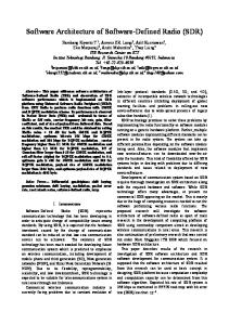
Vol. 5, Issue 5, May 2016 transmitter and transmitted as text, audio or image after modulation. Then the receiver received the signal by recording it. The information obtained after demodulation. II. TRANSCEIVER MODEL AND ASSUMPTIONS In radio communication system high frequency signal has been transmitted. On one hand, only the signal with high frequency can be transmitted over a long distance; on the other hand, the height of antenna has a strong relationship with the signal frequency. The lower the frequency is the higher the antenna is. Thus transmission of low frequency signal requires a very high antenna which even cannot be made out. Whenever the signal with low frequency needs to be transmitted it is necessary and important to modulate it to a high frequency signal. Only in this way can the signal be transmitted in the radio communication system. The signal used to carry message is called carrier signal; typically it is a high-frequency sinusoid or cosine waveform. The carrier signal can be transmitted via the air over a long distance. The process of making the radio frequency carrier signal carry the information signal with low frequency is called ‘Modulation’. Modulation can be realized by varying one or more features of a carrier signal. When the receiver receives modulated signal, it has to process the modulated carrier signal and get the original information; this process is demodulation. Its function is opposite to that of modulation. SDR is a Transceiver Architecture which consists of both transmitter and receiver. The Input to the transmitter is a digital data and at the receiver part, the digital data is retrieved back. In transmitter, the data is encoded using the16QAM modulator which is followed by 8-point IFFT which converts the digital data into time domain. Same QDDFS architecture is used both transmitter and receiver. The receiver basically performs the inverse of the transmitter. The FFT converts the digital data into frequency domain data. Demodulation converts the information back to the baseband data. The overall block diagram of the system has been shown in Fig. 1.
Figure 1: SDR Transceiver Model III. RTL-SDR INTRODUCTION: RTL-SDR hardware is low cost and programmable that is easy to use and integrate with technical programming environments such as MATLAB and simulink and to implement and learn SDR by experiencing and doing. The RTL-SDR is a easy to use USB device that receives RF radio signals. Originally these devices were designed to be used as DVB-T(Digital Video Broadcast-Terrestrial), but it was discovered that they could be used as generic (receive only) SDRs by simply putting them into a different mode. In this mode, they are capable of receiving any signal in the range their tuner operates over, not just the digital television (DTV) signals they were designed to receive. This range varies from device to device depending on what components have been used, but is most commonly from 25MHz to 1.75GHz. The front end of the RTL –SDR receives RF signals live off the air, down converts them to base band, digitize them, and the device outputs samples of the baseband signal across its USB interface.
Copyright to IJAREEIE
DOI:10.15662/IJAREEIE.2016.0505126
4388
ISSN (Print) : 2320 – 3765 ISSN (Online): 2278 – 8875
International Journal of Advanced Research in Electrical, Electronics and Instrumentation Engineering (An ISO 3297: 2007 Certified Organization)
Vol. 5, Issue 5, May 2016
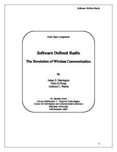
MathWorks released a Hardware Support Package for the RTL-SDR in early 2014 which enables both MATLAB and simulink to interface with, and control the RTL-SDR. With this add-on, the output samples from the device can be captured and brought into the software, enabling users to implement any kind of DSP receiver or spectrum sensing system they desire in either a simulik model or MATLAB code. The RTL-SDR had been connected to the laptop and the antenna to the RTL-SDR’s RF input port, MATLAB code used to tune the device to any frequency, the received samples were demodulated and decoded and finally the output is got. As the entire demodulation process was carried out in software, this is a Software Defined Radio implementation. STRUCTURE OF RTL-SDR: The RTL-SDR set up is represented in a block diagram form in figure 2. RF signals are received at the antenna, quadrature down converted by the RTL-SDR and in phase/quadrature phase samples are presented to the computer running MATLAB. The receiver design is implemented using the appropriate DSP algorithms to demodulate the signal to baseband and extract the information signal. This might be audio, image, video or data. Subject to appropriate hardware configuration (i.e. using the right antenna) and signals being broadcast in the vicinity, the RTL-SDR receives not only FM radio signals, but also UHF/DTV signals.
Figure 2: Block diagram of the RTL-SDR receiver chain IV. SECURITY Secure communication includes means by which people can share information with varying degrees of certainty that third party cannot know what was said. This paper proposes a novel method for adding security in digital communication system through variations in gray coded mapping scheme in typical rectangular QAM. This has been achieved by varying the constellation mappings where by each symbol is mapped to a different amplitude and phase level in a constellation plot at each variation (hop) without breaking the rules of gray coding i.e. only a single bit difference between adjacent symbols is maintained. The main focus was on reconfigurable software defined radio (SDR) because the reconfiguration of mappings is very difficult to be achieved in hardware. An important fact is that the application of security does not cause undesirable effects. That is to say that the Bit Error Rate (BER) vs. Signal to Noise Ratio (SNR) curves are not deteriorated and remain constant for each variation as explained in Section V. Secondly the use of Bandwidth also stays constant unlike the Frequency Hopping Spread Spectrum (FHSS) technique where the security is achieved at the expense of increased bandwidth In addition further security can be achieved if these mapping schemes are varied pseudo randomly after a specified period of time. The ideas of hopping period and the number of hopping frequencies as used in FHSS can also be applied in the proposed method with a little alteration in the terminology. For example the time interval during which the communication system will work on any one of possible mapping schemes is still termed as hopping period, however we are not dealing with hopping frequencies here, instead we are hopping between various constellation mappings. It remains obvious that the shorter the hopping period and the higher the number of hopped mappings, the more secure is the communication system
Copyright to IJAREEIE
DOI:10.15662/IJAREEIE.2016.0505126
4389
ISSN (Print) : 2320 – 3765 ISSN (Online): 2278 – 8875
International Journal of Advanced Research in Electrical, Electronics and Instrumentation Engineering (An ISO 3297: 2007 Certified Organization)
Vol. 5, Issue 5, May 2016 V. RESULT AND DISCUSSION Fig.3 indicates the acceptance of text input in form of ASCII for respective input frequency.
Fig. 3 Acceptance of Text input
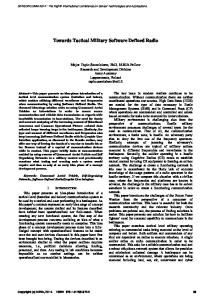
Fig.4 shows the QAM-16 constellation which exhibits the custom mapping to enhance security.
Fig. 4 Enhancing SDR security using custom mapping
Copyright to IJAREEIE
DOI:10.15662/IJAREEIE.2016.0505126
4390
ISSN (Print) : 2320 – 3765 ISSN (Online): 2278 – 8875
International Journal of Advanced Research in Electrical, Electronics and Instrumentation Engineering (An ISO 3297: 2007 Certified Organization)
Vol. 5, Issue 5, May 2016 Fig.5 exhibits cosine and sine signals from QDDFS in the transmitter end.
Fig .5 Cosine and sine signals from QDDFS Fig.6 proves the complete transmission of the input text.
Fig. 6 Reception of text Fig.7 shows the image transmission using two types of modulation of 16-QAM and 64-QAM.
Fig.7 Image transmission
Copyright to IJAREEIE
DOI:10.15662/IJAREEIE.2016.0505126
4391
ISSN (Print) : 2320 – 3765 ISSN (Online): 2278 – 8875
International Journal of Advanced Research in Electrical, Electronics and Instrumentation Engineering (An ISO 3297: 2007 Certified Organization)
Vol. 5, Issue 5, May 2016 VI. CONCLUSION The outcome of this project produced a simulation of a transceiver for any frequency band that can be tuned down to any frequency. The social impacts of this product are not easily identifiable, though the Software Defined Radio concept has been creeping up in years and is demonstrated today on the cellular networks, a very important part of many people’s lives. The problem of frequency spectrum scarcity and under utilization can be overcome by Cognitive Radio for which SDR is the core. REFERENCES [1] Ali, F.A.Kalsait, S.Suleman, M.U and Tabassam, A.A. “Building Software-Defined Radios in MATLAB Simulink - A Step Towards Cognitive Radios Computer Modelling and Simulation”, UkSim 13th International Conference.,2011. [2] Aluru Koteswara Rao and Anasuyamma, A. “Implementation of FPGA Architecture for OFDM-SDR with an optimized Direct Digital Frequency Synthesizer”, International Journal Of Engineering And Computer Science ISSN:2319-7242 Volume 4, Page No. 13388-13394, 2015. [3] Bindiya Kamboj and Rajesh Mehra, “Efficient FPGA Implementation of Direct Digital Frequency Synthesizer for Software Radio”, International Journal of Computer Applications, vol. 37, no. 10,pp. 25-29, 2012. [4] Behrouz Forouzan, “Data Communications and Networking, Bandwidth Utilization: Multiplexing and Spreading: Spread Spectrum”, 4th Edition. [5] D. A. Sunderland, S. S. Strauch, H. Wharfield, T. Peterson, and C. R. Cole, “Cmos/sos frequency synthesizer vlsi circuit for spread spectrum communications”, IEEE Journal of Solid-State Circuits, vol. 19, no. 4, pp. 497–566,2003. [6] Hazrat Ali, Xianwei Zhou and Khalid Iqbal, “FPGA Architecture for OFDM Software Defined Radio with an optimized Direct Digital Frequency Synthesizer”,2013. [7] H. T. Nicholas, H. Samueli, and B. Kim, “The optimization of direct digital frequency synthesizer in the presence of finite word length and effects of performance” 42nd Annual Frequency Control Symposium, Baltimore, MD, pp. 357–363,1988. [8] Indranil Hatai and Indrajit Chakrabarti “A High-Speed, ROM-Less DDFS for Software Defined Radio System”, IEEE journal of Solid-State Circuits, Vol.45, No.11, pp. 115 – 119,2010. [9] Mandava Akhil Kumar, Pillem Ramesh, “A Novel Design in Digital Communication using Software Defined Radio”, International Journal of Engineering Trends and Technology, vol. 4, issue 4, pp. 1096-1100,2013. [10] Rajesh Mehra and Swapna Devi ‘FPGA implementation of High Speed Pulse Shaping Filter for SDR Applications’, SpringerLink Recent Trends in Networks and Communications in Computer and Information Science, Vol. 90, Part 1, pp. 214-222,2010. [11] Regulagadda Srinivasa Aditya and Suresh Angadi, “Software Defined Radio Theoretical Analysis and Design Approach”, International Journal of Engineering Trends and Technology (IJETT) - Volume4Issue5,2013. [12] Sivagami. A, Shoba. B and Raja, P ‘An Efficient Design and Implementation of Software Radio System”, International Journal of a Technology and Engineering System, vol. 2, no. 2, pp. 210-216,2011. [13] The Mathworks Inc, Matlab, Getting Started with Matlab, Natick, Massachusetts, U.S.A, 1999. [14] The Mathworks Inc, Simulink, Dynamic System Simulation for Matlab, Using Simulink, Natick, Massachusetts, U.S.A, 1999. [15] Vishnu. G, Karthik. P and Fathima Jabeen “VLSI Implementation of Software defined radio using Optimized Quadrature Direct Digital Frequency Synthesizer on FPGA”, Second International Symposium on Computer Vision and the Internet (VisionNet’15) Procedia, Computer Science 58 : 414 – 421,2015. [16] Wei Deng, Shoichi Hara, Ahmed Musa, Kenichi Okada and Akira Matsuzawa (2014) ‘A Compact and Low-Power Fractionally InjectionLocked Quadrature Frequency Synthesizer using a Self-Synchronized Gating Injection Technique for Software-Defined Radios’, IEEE Journal of Solid-State Circuits, vol. 49, no. 9, pp. 1984- 1994. [17] Qi, L. Xiao, and S. Zhou, ‘A novel GPP-based Software-Defined Radio architecture’, 7th International ICST Conference on Communications and Networking, Kun Ming China, 8-10 August, pp. 838 – 842, 2012. [18] Yongchul Song, ‘Quadrature Direct Digital Frequency Synthesizers Using Interpolation-Based Angle Rotation’ IEEE Transactions of very large scale integration (VLSI) systems, Vol. 12, No. 7, 2004. [19] Z.C. Alex, Shriram.K and VasudevanSivaraman.R, “Software Defined Radio Implementation (With simulation & analysis), International Journal of Computer Applications (0975 – 8887) Volume 4– No.8.Saad Islam, Muhammad Ali, Umair Nasir, Fatima Ajmal, Salman Ali and Adnan Rashdi (2009) Enhancing Software Defined Radio (SDR) security using variations in Gray Coded Mapping Scheme in Rectangular QAM”, IEEE978-1-4244-3314-8/09,2010.
Copyright to IJAREEIE
DOI:10.15662/IJAREEIE.2016.0505126
4392