Original Article
www.jmss.mui.ac.ir
Design and Implementation of a Portable Impedance Cardiography System for Noninvasive Stroke Volume Monitoring Hassan Yazdanian, Amin Mahnam, Mehdi Edrisi1, Morteza Abdar Esfahani2 Departments of Biomedical Engineering and 1Electrical Engineering, University of Isfahan, 2Department of Cardiology, Isfahan University of Medical Sciences, Isfahan, Iran Submission: 01‑12‑2015
Accepted: 15‑01‑2016
ABSTRACT Measurement of the stroke volume (SV) and its changes over time can be very helpful for diagnosis of dysfunctions in the blood circulatory system and monitoring their treatments. Impedance cardiography (ICG) is a simple method of measuring the SV based on changes in the instantaneous mean impedance of the thorax. This method has received much attention in the last two decades because it is noninvasive, easy to be used, and applicable for continuous monitoring of SV as well as other hemodynamic parameters. The aim of this study was to develop a low‑cost portable ICG system with high accuracy for monitoring SV. The proposed wireless system uses a tetrapolar configuration to measure the impedance of the thorax at 50 kHz. The system consists of carefully designed precise voltage‑controlled current source, biopotential recorder, and demodulator. The measured impedance was analyzed on a computer to determine SV. After evaluating the system’s electronic performance, its accuracy was assessed by comparing its measurements with the values obtained from Doppler echocardiography (DE) on 5 participants. The implemented ICG system can noninvasively provide a continuous measure of SV. The signal to noise ratio of the system was measured above 50 dB. The experiments revealed that a strong correlation (r = 0.89) exists between the measurements by the developed system and DE (P 0.[47] According to Eq. 1, Zout can be improved by using tightly matched resistors, large R1/(R1+R2), large R2b, large resistors in the design, and high AOL (jω). Thus, in this design, R1/(R1+R2) was considered 1/3, and R2a and R2b were 6 kΩ with 0.1% tolerance. AD818 op‑amp was used in this design with 70 dB open loop gain at 50 kHz. By these values, Eq. 1 predicts Zout = 1.107 MΩ. The supply voltage of the circuit was set to ±15 V. For an output current amplitude of 2 mA, the sine wave voltage generated by DDS was amplified to 12 Vp‑p using an inverting amplifier based on AD844 and then was fed to negative input of HCP while the positive input of HCP was grounded. According to Eq. 2 by these parameters, the RLoad(max) is 660 Ω. The designed HCP was carefully constructed on a double‑layer printed circuit board. It was tried to keep the length of positive and negative feedback traces short and the same, so that the trace impedance become much smaller than the resistor tolerances (0.1% precision). The symmetrical layout was used to achieve excellent matching. The generated voltage by DDS was fed to HCP through an inverting amplifier (AD844). The output impedance of the AD844 (0.2 Ω at 50 KHz) was noted to be small enough to maintain the matching between positive and negative feedback loops. These considerations helped to achieve a practically high output impedance and, therefore, precise measurements. The other factor that was considered in the design of HCP was that in long‑term operation, the total charge injected to the body must be zero which means that the DC error of the current source must be as small as possible. To achieve this, a large R2b was used, and the resistors for negative and positive feedback loops were set equal.[47] Further, the input bias current and offset voltage of the op‑amp was small.
Voltage Measurement
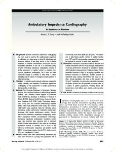
Figure 3: Standard Howland current pump 50 Journal of Medical Signals & Sensors
The safety standards for the patient necessitate that the applied current as the stimulus for measuring the thorax impedance is kept as low as possible. This results in a very low response voltage on the tissue and necessitates very precise and stable measurement block. IAs are usually used for biopotential measurements. However, the measured potential here is at 50 kHz which requires a very high slew rate for IA. Its bandwidth must also be at least one decade Vol 6 | Issue 1 | Jan‑Mar 2016
Yazdanian, et al.: Portable ICG system for stroke volume monitoring
higher than 50 kHz for avoiding signal attenuation. The other factor is the input impedance of the IA, which must be significantly higher than the electrode‑tissue impedance. INA111 is a high speed, FET‑input IA offering excellent performance at kHz frequencies.[48] The high CMRR above 60 dB at 50 kHz minimizes common mode interferences and eliminates the effect of any DC residual component that may arise. To avoid DC drift, low‑frequency noise, and degradation of the SNR and CMRR, the output of INA111 was fed to a band‑pass filter with a center frequency of 50 kHz. This filter consists of a 40 kHz second order Butterworth high pass filter and a 60 kHz fourth order Chebyshev1 low pass filter. These filters were designed in FilterPro (Texas Instrument, USA) software.
Demodulator and Antialiasing Filter A precise AM demodulator (or peak detector) is needed to extract the ICG signal that is an amplitude‑modulated signal on the 50 kHz carrier. The extracted signal consists of two important components: The constant component that reflects the base thoracic impedance (Z0 = V0/Iout, where V0 is the constant component of the demodulated voltage and Iout is the amplitude of HCP output current), and the time varying component that reflects changes in the volume of blood mainly in the aorta (ΔZ = ΔV/Iout, where ΔV is the time varying component of the demodulated voltage). The typical ranges of Z0 and ∆Z are 20–35 Ω and 0.1–0.4 Ω, respectively.[7] Figure 4 shows the schematic of the envelope detector used in this design. The circuit is a precise half‑wave rectifier and an RC low pass filter. Since the frequency of Vin is high (50 kHz), diode D must be a high‑speed diode. To remove high‑frequency components and maintain the desired envelope, Tcarrier