Proc. of World Cong. on Multimedia and Computer Science
Design and Implementation of a Path Tracking Steering Controller for EO Smart Connecting Car Mohammed Ahmed1and Mehmed Yu¨ksel2 1
German Research Center for Artificial Intelligence (DFKI) - Robotics Innovation Center, Bremen, Germany 1
[email protected],
[email protected]
Abstract: Within this paper, we reconsider the path-following problem with the objective to synthesize a control law which allows the prototype electric vehicle EO smart connecting car 2 to autonomously follow a desired path in a stable manner. Furthermore, the software architecture controlling the car and all its subsystems is depicted. A hardware-in-the-loop (HIL) frame work that can provide an effective platform for developing and testing different subsystems of the vehicle in real-time is described and the general workflow is outlined. The performance of the designed controller is discussed and demonstrated with realistic simulations. An experiment with the HIL framework interfaced to the car is presented, conclusions and an outlook of future work are also given. Keywords: Electric Vehicle, Path Following, Automatic Steering, Hardware-in-the-loop, Software-in-the-loop, nonlinear systems, real-time control
I. INTRODUCTION EO smart connecting car 2 (EO2) is a two seated intelligent electric vehicle which is the second generation of EO car [1][2]. EO2 is a four wheel-driving electric vehiclewith extended manoeuvrability through its innovative suspension/axle design, optimized wheel hub motors, and high urbancapability thanks to its foldable body and high adaptivity with a coupling mechanism for Car2Car or Car2Extender modules.EO2 is developed to use drive assistance and autonomous driving systems. Fundamental to the design of an Ackerman steered autonomous driving system is the development of a lowlevel controller that effectively performs trajectory or path tracking. In the field of autonomous vehicle guidance, navigation and control, path-following problem of car-type vehicles is of particular interest. Though ample literature is available on various methods for controlling ground vehicles with various techniques and strategies for this problem [3][4][5][6][7][8], little information is presented on the implementation and tuning of such controllers. Recent trends in automotive industry point in the directionof increased content of electronics, computers, and controls with emphasis on the improved functionality and overall system robustness. For this reason and to enhance the design, implementation, and test of such components and subsystems, rapid control prototyping (RCP) tools are used for car development and optimization [9][10]. The RCP real-time units are used as interface for electro-mechanical subsystems of these vehicles for different application fields, such as engine 1
EO means ”I go” in Latin, however, the true meaning is more ”to there”, in the sense of being on the way to a goal
DOI: 02.WCMCS.2013.1.4 © Association of Computer Electronics and Electrical Engineers, 2013
control units (ECU) and vehicle control units (VCU)[11].They perform different functions like x-by wire (steer-brake throttle)as well as data logging, and interfacing for different applications (sensor integrations, gateway or bypassing for data buses etc.) [12]. Because of these benefits, RCP units are integrated into autonomous vehicles as low-level vehicle controllers and as subsidiary for autonomy (high-level) controllers in test development platforms [13][7][14]. This work presents an approach to design and implement a proportional input-Scaling feedback controller for a vehicle to follow a desired path, using its forward velocity and angular acceleration as control inputs. For this controller, a kinematic vehicle model is used to map from the path curvature specified by the given path to the vehicle’s actual steering angle. This controller is then tested in a co simulation framework that utilizes a dynamic model to predict the vehicle’s response to a series of different steering inputs. Successful trajectory control results for the ISO3888-2 double lane change test track and the implemented RCP environment and work flow for development, test and verification of the controller and various other subsystems are presented. II. PATH FOLLOWING MODULE This module implements how the vehicle tracks a reference path via the control of its actuators. The module is being implemented based on simple and effective control strategies. Our approach consists of applying a control signal based on state feedback control. The implementation supposes that one is able to measure the variables involved in the control loop (typically the position and orientation of the vehicle with respect to either a fixed frame or a path that the vehicle should follow). A. Vehicle Model The vehicle kinematic model approximates the mobility of a car [15]. The configuration of non holonomic vehicle [6] is represented by the position and orientation of its main in the plane, and by the angle of the steering wheels.
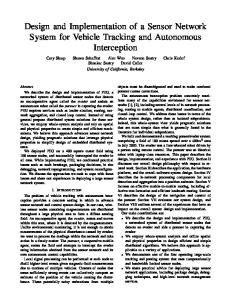
Figure 1. Configuration variables of the vehicle kinematic model
Two velocity inputs are available for motion control. This situation covers in a realistic way our car. The non holonomic nature of the car is related to the assumption that the car wheels roll without slipping. The kinematic model used (shown in Fig.1)is given as:
x u1 cos y u1 sin
(1)
u 1 tan L u2 where (x,y) represents the coordinates of the point P locatedat mid-distance of the actuated wheels, the angle characterizes the vehicle chassis orientation,represents the vehicle steering wheel angle, and L is the 14
distance between the rear and front wheels axles. In this equationu1, u2 and represents the driving and the steering velocity input, respectively. B. Path Reference Frames The analysis is limited to the case of a vehicle workspace free of obstacles. In fact, it is implicitly considered that the controller is to be embedded in a hierarchical architecture in which a higher–level planner solves the obstacle avoidance problem and provides a series of motion goals to the lower control layer. In this perspective, the controller deals with the basic issue of converting ideal plans into actual motion execution. Wherever appropriate, the interactions between feedback control and motion planning primitives shall be highlighted, such as the generation of open-loop commands and the availability of a feasible smooth path joining the current vehicle position to the destination.
Figure 2. Path-following geometric reference frames
Let us consider a curve Cin the plane of motion (Fig.2). s is the curvilinear abscissa at Ps by projecting P orthogonally on C. This point exists and isunique if the point Pis close enough to C.
dis the ordinate of Pin Fs; its absolute value is also the distance between P and C.
θe = θ − θsis the angle characterizing the orientation of the car chassis w.r.t Fs.
The equations of motion of P w.r.t C can be expressed based on the three variables s, d, and θe as follows:
s
u1 cos e 1 dc(s )
d u1 sin e
(2)
u (s ) e 1 tan sc L u2 The model (2) is transformed to the chained form [16] through the change of coordinates and control variables (s, d, θe , u1 , u2 ) (z1 , z2 , z3 , v1 , v2 ) defined by:
15
z1 s,
z2 d , (3)
z3 1 dc(s) tan e ,
z4 c(s) 1 dc(s) 1 2 tan 2 e
c(s) tan 2 tan e 1 dc(s) ; s L cos3 e
d
v1 z1 , v2 z4 The (2, 4) single-chain form (3), although nonlinear, has a strong underlying linear structure. This clearly appears when u1is assigned as a function of time, and is no longer regarded as a control variable. In this case, (3) becomes a single-input, time-varying linear system. C. Path Following with Orientation Control The control law should asymptotically stabilize (d = 0, θe=0) and also ensures that the constraint on the distanced to the path (i.e.,|dc(s)|