DESIGN AND IMPLEMENTATION OF A MOBILE PHONEBASED ROUTE DETECTION SYSTEM FOR SECURITY APPLICATIONS
MULUMBA DORCUS NTHOKI (B. Ed. (Sc.)) I56/CE/15669/2005
A thesis submitted to the School of Pure and Applied Sciences in partial fulfillment of the requirements for the award of the degree of Master of Science of Kenyatta University.
NOVEMBER, 2013.
ii
DECLARATION This thesis is my original work and has not been presented for the award of a degree or any other award in any other University.
Signature……………….
Date.……………
Mulumba Dorcus Nthoki Department of Physics
We confirm that the candidate carried out the work reported in this thesis under our supervision.
Signature………………
Date.……………
Dr. Patrick M. Karimi Department of Physics Kenyatta University.
Signature……………....
Date.……………
Dr. Muchemi Gakuru Department of electrical/Electronics Engineering University of Nairobi.
iii
DEDICATION This thesis is dedicated to my dear husband Titus Khamala, daughters; Cindy and Joy. Always let the sky be the limit.
iv
ACKNOWLEDGEMENTS I would like to sincerely thank my research supervisors; Dr. Patrick M. Karimi and Dr. Muchemi Gakuru who have been my mentors during this period of my research. With their able guidance and support, I met the research objectives with motivation and dedication. I particularly thank the Kenya National Council of Science and Technology (NCST) for funding this research. With their help, I acquired the software and the accessories required to implement this project. I also secured the domain name and hosted the system online.
I thank the chairmanof the Physics department of Kenyatta University Dr. Walter Njorogefor being inspirational to me throughout the study. I also thank the laboratory technical staff led by Mr. Simon Njuguna, for guiding me in using some of the laboratory devices. My sincere gratitude also goes to fellow colleagues namely: Tuwei, Kagiri, Tabitha and Martin. I dearly thank you all for your support and advice during this research period.
My sincere appreciation goes to my parents for their unconditional love, support and encouragement. To my dear husband Titus who has been a source of unlimited love, inspiration, support, motivation, encouragement and strength; thank you so much.
Last but not least, I thank the Almighty God who has given me life, health, strength and determination to complete this research work.
v
TABLE OF CONTENTS
DECLARATION
ii
DEDICATION
iii
ACKNOWLEDGEMENTS
iv
TABLE OF CONTENTS
v
LIST OF TABLES
viii
LIST OF FIGURES
ix
LIST OF ABBREVIATIONS AND ACRONYMS
xi
ABSTRACT
xiv
CHAPTER ONE: INTRODUCTION1 1.1 Background to the study
1
1.2 Problem statement and justification
4
1.3 Objectives of the study
5
1.3.1 Main objective
5
1.3.2 Specific objectives
5
1.4 Rationale of the research
6
CHAPTER TWO: LITERATURE REVIEW7 2.1 Introduction
7
2.2 Location Based Services (LBS) technology applications
7
2.2.1 Emergency relief, public safety and security
7
2.2.2 Navigation aids, commercial and information services
8
2.2.3 Business safety and efficiency, transaction and billing
8
2.3 Other related work 2.3.1 Monitoring systems on mobile phones
9 9
vi
CHAPTER THREE: THEORETICAL BACKGROUND14 3.1 Introduction
14
3.2 Determination of the location of a mobile terminal
14
3.2.1 Device-based positioning methods
14
3.2.2 Network-based positioning methods
16
3.2.3 Hybrid positioning methods
18
3.3 Software developer methods for obtaining position data
19
3.3.1 Handset-initiated location requests
19
3.3.2 Network-initiated location requests
24
3.4 Global Positioning System (GPS) technology
24
3.4.1 GPS signal transmission and reception
26
3.5 The point-in-polygon problem
29
3.5.1 The angle summation algorithm
29
3.5.2 The grid test
30
3.5.3 The ray casting method
30
3.6 Calculation of speed using GPS coordinates
35
3.7 Client/server systems
37
3.8 Global System for Mobile (GSM) communications network
38
3.8.1 Mobile Station (MS)
39
3.8.2 Base Station Subsystem (BSS)
40
3.8.3 Network and Switching Subsystems (NSS)
40
3.9 Short Message Service (SMS)
41
CHAPTER FOUR: MATERIALS AND METHODS42 4.1 Introduction
42
4.2 Block diagram of the complete mobile phone-based security system
42
vii
4.3 The J2ME application (TrackMe) 4.3.1 The J2ME code 4.4 The server-side development 4.4.1 The My Structured Query Language (MySQL) database
43 45 46 47
4.5 The route-geo-system application
48
4.6 The Ozeki-NG SMS gateway
50
CHAPTER FIVE: RESULTS AND DISCUSSIONS51 5.1 Introduction
51
5.2 The J2ME application
51
5.3 The server-side
57
5.4 The route-geo-system
57
5.4.1 The system‟s response to deviation from the route
60
5.4.2 The system‟s response to the speed limits
62
5.5 The Ozeki-NG SMS gateway
63
5.6 The working of the whole system
63
CHAPTER SIX: CONCLUSION AND RECOMMENDATIONS64 6.1 Conclusion
64
6.2 Recommendations
65
REFERENCES67 APPENDICES70 APPENDIX A: THE J2ME CODE
70
APPENDIX B: THE ROUTE-GEO-SYSTEM CODE
73
APPENDIX C: THE SERVER SIDE
84
APPENDIX D: OZEKI-NG SMS GATEWAY
86
viii
LIST OF TABLES Table 3.1: Location technologies for cellular phones……………………………...15 Table 5.1: Latitude/longitude co-ordinates for Nyayo Route ……………………..53 Table 5.2: Latitude/longitude co-ordinates for Gate Route……………………......56 Table 5.3: Route descriptions/characteristics…………………………………........60 Table 5.4:Percentage success rates for the system‟s response to deviation ……….62
ix
LIST OF FIGURES Figure 3.1:The Cell-ID positioning method ……………………………………...17 Figure 3.2: Handset-initiated versus network-initiated location requests …………19 Figure 3.3:J2ME architecture; including relationship to proprietary APIs………..21 Figure 3.4: The GPS Constellation………………………………………………...25 Figure 3.5: The GPS pseudo range observation in relation to the satellite and receiver clocks ……..…..................................................................27 Figure 3.6: Angle summation test ………………………………………………....30 Figure 3.7: The grid method….................................................................................31 Figure 3.8: The ray casting method; Point A is inside, but point B is outside the polygon……………………………………………………32 Figure 3.9: The region changes of edges (ei) with respect to a ray (r) ..…………...33 Figure 3.10: A ray casted through a triangular polygon …………………………..34 Figure 3.11:The flow chart diagram for the ray casting algorithm used in this work…………………………………………………….36 Figure 3.12:Client and server connect through a network ………………………..38 Figure 3.13: Layout of generic GSM network ………………………………….....39 Figure 4.1: The system architecture of the designed security system. …………….43 Figure 4.2: A block diagram showing the main J2ME application components and the information flow for the system………………………………45 Figure 4.3: A figure showing how the routes were buffered to form polygons in this work ….……………………………………………...47 Figure 5.1: Forms shown on the emulator when the J2ME application is run…….52 Figure 5.2: A map of Kenyatta University showing the mapped Nyayo route…….53 Figure 5.3: A graph of longitude against latitude for Nyayo route….......................54
x
Figure 5.4: A map of Kenyatta University showing the mapped Gate route……....55 Figure 5.5: A graph of longitude against latitude for Gate route…………………..56 Figure 5.6: A screen shot of database designed in this work showing the six tables…………………………………………………………...57 Figure 5.7: A screen shot of the user interface designed in this work for editing the route details………........................................................58 Figure 5.8: A screen shot of the user interface after the route data has been successfully updated………………………………………...59 Figure 5.9: A screen shot of the user interface for editing the guardian‟s phone number………………………………………………………….59 Figure 5.10: A screen shot of a person walking at the middle of the road carrying a J2ME enabled phone ……………………………………...61
xi
LIST OF ABBREVIATIONS AND ACRONYMS AFLT
Advanced Forward Link Trilateration
A-GPS
Assisted GPS
APIs
Application Programming Interfaces
ATM
Automated Teller Machine
AuC
Authentication Center
BSC
Basic Station Controller
BSS
Base Station Subsystems
BTS
Base Transmitter Station
CDLC
Connected Limited Device Profile
CDMA
Code Division Multiple Access
Cell-ID
Cell Identification
DBMS
Database Management System
EIR
Equipment Identity Register
E-OTD
Enhanced Observed Time Difference
FCC
Federal Communication Commission
GIS
Geographic Information System
GPL
General Public License
GPRS
General Packet Radio Service
GPS
Global Positioning System
GSM
Global System for Mobile
HLR
Home Location Register
HTTP
Hypertext Transfer Protocol
IDE
Integrated Development Environment
IM&L
Instant Messaging and Locator
xii
IT
Information Technology
J2EE
Java 2 Enterprise Edition
J2ME
Java 2 Micro Edition
J2SE
Java 2 Standard Edition
JSR
Java Specification Request
LBS
Location Based Services
ME
Mobile Equipment
MHz
Mega Hertz
MIDP
Mobile Information Device Profile
MMS
Multimedia Messaging Service
MS
Mobile Station
MSC
Mobile Switching Centre
MYSQL
My Structured Query Language
NCST
National Council of Science and Technology
NCTR
National Center for Transit Research
NSS
Networking & Switching Subsystems
OS
Operating System
PDA
Personal Digital Assistant
PHP
Hypertext Preprocessor
PSAP
Public Safety Answering Point
QoS
Quality of Service
RFID
Radio Frequency Identification
S/A
Selective Availability
SIM
Subscriber Identity Module
SMS
Short Message Service
xiii
SQL
Standard Query Language
TDOA
Time Difference of Arrival
TOA
Time of Arrival
TTFF
Time To First Fix
USB
Universal Serial Bus
U-TDOA
Uplink Time Difference of Arrival
VLR
Visitor Location Register
WLAN
Wireless Local Area Network
WTK
Wireless Tool Kit
xiv
ABSTRACT In the area of security, industry and academia have actively conducted research and implemented several systems which can be used to enhance security. However, many of these systems are not always suitable for outdoor activities and also their cost is very high. An easily portable and a versatile device like a mobile phone become handy for enhancing personal security. In this work, an optimal mobile phone-based route detection application has been developed. It locates and monitors the users‟ movements and notifies the required personnel if deviation from the predesignated route is detected. This client-server application is made up of mainly four software parts. The first client part runs on the users‟ GPS, Java 2 Micro Edition (J2ME)-enabled mobile phone and periodically sends its position data to an internet enabled database server after every 30 seconds. It is developed using the Sun‟s J2ME, Mobile Information Device Profile (MIDP), under the Connected Limited Device Configuration (CLDC). The Netbeans Wireless Tool Kit (WTK) was used as a testing and emulation environment. The route-geo-system application part then uses the point-in-polygon algorithm to determine whether the user is within the required route and speed. If not, it generates and sends an alert message to the „message-out‟ table of the database server. The Ozeki-NG Short Message Service (SMS) gateway then picks this message and delivers it to the required personnel. In testing the performance of whole system, no alarms are sent between 0-30 meters from the middle of the road. However, as one deviates several meters from the road, alarms are sent. The systems response to the speed limits is 100% successful. The total time taken as from the time the user deviates from the route to the time the alert is send is averagely 40 seconds.
1
CHAPTER ONE: INTRODUCTION
1.1 Background to the study The first generation mobile phones which used analog technology were heavy and their coverage was patchy. Technical innovations in terms of hardware, software and protocols have contributed to the success of the mobile phones and have added them new capabilities. The handsets have become smaller and lighter, the battery life has increased and the reception has improved due to the improvements in digital technology and better use of the finite spectrum. The current generation of mobile phones is built using digital technology and they connect to the internet via the new generation of wireless communications. Therefore, they provide higher information transfer capability than the earlier generations (Yesim and Kivanc, 2007).
Due to the advancement of mobile phones and wireless technologies, data functionalities (such as the text or multimedia messages, email and streaming video) are now possible at a variety of broadband speeds, making the popularity of these media soar. The mobile terminals are developing, getting new features and enhanced hardware at a fast pace. The new mobile phones are called smart phones, because their features can be added and modified. Most of these smart mobile phones are programmable and can run any conceivable application. They readily support General Packet Radio Service (GPRS), Bluetooth, Multimedia Messaging Service (MMS), inbuilt or attachable camera, as well as other sophisticated applications. The smart phones have high-resolution color display (176x208 pixels with 4096 colors) and several megabytes of internal memory, which can be supplemented with
2
memory cards. They are small, light, but powerful mobile terminals (Tsalgatidou et al., 2005).
Mass production has substantially lowered the cost of smart phones on the cellular phone market making them more affordable to the average consumer. It is estimated that currently over one half of the world‟s population own a mobile phone (Winters et al., 2008). The convergence of multiple technologies including GPS, GIS, mobile information systems, internet, wireless communications, location identification and mobile devices has given rise to exciting new types of information utilities called Location Based Services (LBS).
They provide the capability to find the
geographical location of the mobile device and then offer services based on information of this location (Steiniger et al., 2006).
Location Based Services (LBS) are especially used in special circumstances such as driving or walking; thus the user is not piled with large amounts of information that may distract his/her attention. A mobile environment imposes strong constraints on the implementation of LBS because mobile devices have limited memory, low computational power and small screen size with low resolution, short battery life and uncomfortable input tools that usually do not allow a user to operate quickly. Besides, mobile networks are characterized with limited bandwidth, high latency, low connection stability and low predictable availability (Yesim and Kivanc, 2007). By taking all these constraints into consideration along with user‟s high performance and good service demands that conflict with them, an optimal security application for java-enabled mobile phones has been designed and implemented in this research.
3
Location awareness plays a major role in security enhancement and several applications have been proposed that rely on knowing or predicting the location of the user. Several key issues should be addressed when designing location-aware software applications that require real-time traveler information using GPS-enabled mobile phones. First, the user experience is severely constrained due to the limited user interface. To provide an effective user experience, every effort must be made to design intelligent applications which require user input only when necessary (Maharj et al., 2009). Therefore, a predictive mechanism is desired that will passively monitor traveler‟s transit behavior.
Another consideration for designing traveler security systems is the underlying circumstances. In case the user is attacked in a kidnap, which in many cases the attackers force the user to deviate from his usual route to unusual destinations, he/she may not be in a position to call the care-givers for help. Therefore, a system that is automated to immediately inform the care-givers of any deviations from the route is required.In recent research, route prediction is being extensively examined for use in the context of mobile and wireless computing, towards more efficient network and resource management schemes. If the network can predict where the user is, then considerable bandwidth can be saved and resources optimized for mobility management (Akoush et al., 2006).
In this work, a GPS-enabled phone has been programmed to periodically obtain and send its location data to a database server. This allows one to get real-time information logs about the user‟s movements. The application focusses on monitoring the user while on transit and detects any possible deviation from the pre-
4
destined route or speed range. An alert is send to the required personnel if any of these two aspects is transgressed.
1.2 Problem statement and justification We are living in an insecure society where people are in danger from criminal attacks like kidnaps to internet predators. Systems that can detect situations where the care-givers attention is required exist in form of domestic fire and burglar alarms. In the area of security and health care, industry and academia have actively conducted research using various external sensors such as visual monitors, motion detectors and proximity sensors. However, these sensors may not always be available in outdoor activities. An easily portable and a versatile device like a mobile phone then become handy for enhancing personal security. The expectation that mobile phone users are able to answer phone calls most of the time enables one to determine the well-being of another by simply calling them. However in case of an accident or emergency situation, conditions may not be favorable for any phone call. This raises a question of how to increase awareness of our dependents‟ situations in order to provide help when needed.
Mobile phones equipped with GPS receivers can enable the tracking of one‟s location. This functionality can be used by individuals to identify where they are on a map. However, there are a few problems with the existing GPS security systems. First, the interface for monitoring position requires a lot of user input and is based on plotting a dot on an electronic map. A moving dot on a map only shows information about where the user is located but doesn‟t give detailed information about the type of situation in which he/she may be. Secondly, current GPS systems
5
do not detect any deviations. Guardians are constantly required to focus their attention on the map and assess the situations themselves. In this work, the above issues are addressed by developing a system which can store the user‟s regular routes, monitor him/her while on transit and alert required personnel if there is deviation from the expected route or speed range.
1.3 Objectives of the study 1.3.1 Main objective To develop and implement an optimal mobile phone-based security system, with the ability to locate the user‟s current location, monitor his/her movements and notify the required personnel in the event of deviations from the required route and speed range.
1.3.2 Specific objectives a) To develop the client-side application using Java 2 Micro Edition (J2ME), for the phone to submit its position data periodically to a database server. b) To develop the server-side application, which has a database with tables to receive and update the phones position data, then store all the users possible route data and speed limits. c) To develop an optimal method for detecting deviations from the predetermined route and speed range. d) To develop a mechanism for sending an alert to the required personnel in case of any deviation.
6
1.4 Rationale of the research Currently, security all over the world has become a serious issue, raising a lot of concern among the affected parties. This study increases awareness of the dependents‟ situations and be able to provide help remotely. Therefore, it is deemed that this study is necessary due to the following reasons; a) It will enable the dissemination of mobile terminal‟s position data to third party security service providers ensuring that in case of any criminal attack, necessary measures are taken quickly and effectively. b) It will enable care-givers have peace of mind because they are aware of their dependents‟ movements. c) The system can also be extended to applications like vehicle tracking, asset monitoring and management, monitoring of criminals and location based emergency warnings for public safety.
7
CHAPTER TWO: LITERATURE REVIEW
2.1 Introduction There has been a great development in the design and implementation of locationaware mobile applications and Location Based Services (LBS). This chapter briefly describes some of the applications and systems already developed by other scholars.
2.2 Location Based Services (LBS) technology applications 2.2.1 Emergency relief, public safety and security The driving force behind the LBS technology is a US Federal Communication Commission (FCC) mandate in October 2001 that all operators of mobile communication networks must be able to accurately locate mobile callers requesting emergency assistance via 911 within an accuracy of 50 meters for 67% of emergency calls and within 150 meters for 95% of the calls (FCC Newsletter, 1996). Apart from emergency service there was the need to effectively monitor offenders on parole and trial. Tracking offenders with locator devices would enhance public safety and reduce prison population. Applications related to medical and roadside help can also be developed. Disabled people can be made more independent by tracking them and sending their physiological data to health care providers. Security to teenage children, elderly people can be provided by locating them. Emergency warnings or relief can be given to people by broadcasting alerts that vary with geographical location on their mobile phones (Bajada, 2005; Van-de-Kar and Bouwman, 2001).
8
2.2.2 Navigation aids, commercial and information services Location information interfaced with GIS information can be used to predict user‟s current position and direction towards targets in an unknown environment. Automobile and many other independent manufacturers can offer such services using vehicle-based GPS receivers for mapping and route guide services for road vehicles (Dragos et al., 2007). Current traffic conditions and congestion on roads can be known in advance by integrating with real-time data, so that users can take an alternative route.Potential business applications through which LBS service providers can earn great income is by providing users with the nearest available commercial or leisure information like weather forecast, tourist attraction, restaurants, shopping centers, theatres, gas station and Automated Teller Machine (ATM) locations (Prashant and Houshenghu, 2005).
2.2.3 Business safety and efficiency, transaction and billing Service organization and transport companies can become well-organized, as well as save time and money by tracking their assets. A geo-fence is a virtual boundary on a geographic area such that when that boundary is entered or exited it can be recognized as an event and the user notified of that event. Geo-fencing can be used in asset monitoring and management such as a fleet of vehicles, sales vehicles, employee monitoring or an expensive device that needs monitoring on a regular basis. The notification will tell the user that the asset or the vehicle has entered or left the area and where it is at that point in time. This event information can be sent to a mobile phone as well as to an email account, allowing management by exception (Van-de-Kar and Bouwman, 2001). Using this technology, companies can indirectly gain a competitive advantage and provide improved customer service.
9
Another application of LBS is location sensitive billing, in which the physical fences and gates are replaced with digital ones for parking fees, urban event fees (concerts and conventions) and ticketing for transport (Roza and Bilchev, 2003).
2.3 Other related work 2.3.1 Monitoring systems on mobile phones In the area of home or office security, there have been various external sensors to monitor ones wellbeing, such as external visual sensors, motion sensors and various proximity sensors (Chung, 2006). There are also various types of burglar and fire alarms put in place to ensure security. In the event of a criminal attack in the home, the victim can press a distress call button to alert their security service providers for help. However, a portable device like a mobile phone can more easily enhance personal security for outdoor activities.
The telecommunication industry and mobile phone manufacturers have developed and provided a few services towards increasing safety and security both for the individual and entire families. For example, the project called „Wellbeing at Home‟ by Plomp and Tealdi (2004) uses various external sensors to monitor one‟s wellbeing. These include physiological sensors such as heart beat monitors, external visual monitors, and various proximity sensors. However, for someone participating in activities outside of the home, these sensors are not always available. Although increasing the number of sensors in the home may be useful for increasing awareness of one‟s well-being indoors, few companies around the world provide outdoor services.
10
In South Korea, Palen et al. (2002) developed the „Peace of Mind Service‟, used for monitoring family members while they are on their route to school, to the office and to their homes. This service allows its subscribers to monitor a family member‟s location through GPS coordinates that are sent from their family member‟s phone via Short Messaging Services (SMS) and shows their location on a map in a phone. For example, parents can monitor their child‟s progress towards a destination by looking at a map on their phone which updates its information every five minutes. However, this solution is not sufficient for detecting any deviations.
The „friends-zone‟ service providers have developed the Instant Messaging and Locator (IM&L) service. Location information in IM&L may be displayed in two possible resolutions; relative distance to the users and absolute cell-ID based location. The relative distance is attached to a buddy (friends) list. In addition to the standard buddy list information, such as nickname and virtual presence, there is a vicinity indicator. The vicinity is depicted in four levels: very near (0-0.6 Km), moderate distance (0.6-1.3 Km), far (1.3-2 Km) and out of zone (more than 2 Km). This vicinity indicator is done using the geo-fencing technique (Burak and Sharon, 2005). The E9-1-1 is a public service devised by the US Federation Communication Commission (FCC) for all its citizens such that in case of a criminal attack, fire or any kind of harm, the victim can call the 9-1-1 number for help. The wireless 9-1-1 includes the delivery of the callers call back number and his/her location, to the Public Safety Answering Point (PSAP) so that the dispatched rescue team may locate them.
11
Srinath et al. (2008) developed a navigation and target tracking system for aircrafts. The system acquires GPS-based position data transmitted by target aircrafts and displays it on a PC-based display on the host aircraft. It then gives visual information of every target aircraft in terms of its position, speed and heading. This data is used by pilots and flight test engineers to evaluate the targets performance.
Gipp et al. (2004) developed a system which automatically notifies the emergency medical services in case of a car crash. The notice includes the user‟s current position, which ensures the fastest possible help, and uses multi-cell triangulation to locate the place of the accident. To achieve a more precise localization, it was assayed that GPS is best suited to use in this kind of an application.
In their location modeling paper, Marmasse and Schmandt (2001) discuss a usercentered location model used in „ComMotion‟, which is a location-aware computing environment and links personal information to locations in the user‟s life. In order to trigger the relevant information, they predict the user‟s destination and his or her expected time of arrival. For route learning and destination prediction, they used several pattern recognition and analysis techniques and classified their performances based on the likelihood of the user being on a particular route. These techniques include the Bayes classifier, Histogram modeling and Hidden Markov Model (HMM). The focus here is on destination prediction but doesn‟t monitor the user along a certain route.
Alminas et al. (2004) discussed and presented an algorithm for predicting movement using cell-based location data. The study uses string matching techniques to prepare
12
strings of the cells the user has been and match them against a database of previously stored route fragments to predict the next cell the user will go. However, there are several properties of cells that make them challenging for data analysis and prediction. First, cells widely vary in size and signal shadowing can make them appear non-contiguous. Some cells may have a radius of 3 to 5 Km especially in rural areas, thus predicting the next cell may not show the exact location of the user. Secondly, cells may overlap thus a physical location doesn‟t always have one-to-one correspondence with a cell. With the incoming of GPS-enabled phones in to the market, GPS data becomes the best in performing data analysis for this kind of application because it is more precise.
In their work “Predictive Location-based QoS routing in mobile adhoc networks”, Naresh et al. (2008) used cell-based trajectory modeling to determine the next set of cells a mobile unit will follow. In this type, the geographic area is divided in to regularly shaped cells usually determined by the architecture of the cellular network and the mobile unit‟s location is determined as the cell within which it is contained. The trajectory is expressed as a series of cells making the path of the mobile unit. This method doesn‟t consider the geometry and topology of the actual path and cannot precisely locate a mobile user because the radius of a typical cell is very big. A cell may contain several routes but the provision of a service like routing may require the exact road on which the user is driving (Gipp et al., 2004). Due to these limitations, the cell-based method is not suitable for applications where on-road services are demanded.
13
In this work, an optimal system has been developed in which a GPS-enabled mobile phone obtains and sends its location data, speed and route name to a database server at periodic intervals of 30 seconds. The route-geo-system application then picks this data and determines whether it lies within the specified route and whether the user is travelling within the required speed range. If the user doesn‟t satisfy any of the above conditions, it sends an SMS to the message-out table of the database on the server side. The Ozeki-NG SMS gateway then picks the message and sends it as an SMS alert to the required personnel.
14
CHAPTER THREE: THEORETICAL BACKGROUND
3.1 Introduction Determination of the location of a mobile terminal is one of the most important tasks, which have to be analyzed when implementing location-aware applications. This chapter describes the theoretical considerations of mobile positioning, the software developer methods for obtaining the positioning data and discusses more on the GPS and handset-based methods because they are used in this work. In addition, it also discusses the point-in-polygon problem, the GSM network and the client/server architecture for server-side development.
3.2 Determination of the location of a mobile terminal There are three common classes of positioning techniques that can be utilized to obtain the mobile terminal‟s geographic information: Device-based methods, cellular network-based methods and hybrid methods. Table 3.1 gives a summary of the different positioning technologies for mobile terminals.
3.2.1 Device-based positioning methods This method is based on GPS technology and utilizes the hardware and software that resides in the end-user device to determine the position of the device. Many mobile phones and certain PDAs are equipped with embedded GPS receivers that receive the signals from satellites. The main advantage of GPS is that very highly accurate location data can be obtained within 10 meters of accuracy in ideal scenarios, as shown in table 3.1. This level of accuracy allows the development of real-time applications that interact with the users based on their current position.
For
15
example, vehicle navigation systems that provide the driver with real-time driving directions utilize GPS (Paikannussanasto, 2002).
Table 3.1: Location technologies for cellular phones(Paikannussanasto, 2002). Technology
Type
Accuracy
Cell-ID
Network 100 M-3Km (Depends on the size of the cell)
Cell-ID + Timing Advance
Network Network band size configurable. Default is 500 M
Time of Arrival (TOA)
Network 250-350 M
Angle of Arrival (AOA)
Network
100-200 M
Advanced Forward Link
Network
50-200 M
Trilateration (AFLT) Enhanced Observed Time
Network 50-200 M
Difference (EOTD) Uplink Time Difference of
Network 40-60 M
Arrival (U-TDOA) Global Positioning System
Device
Assisted Global Positioning Hybrid
10-50 M 5-30 M
System (A-GPS)
There are however some disadvantages of GPS that exist. First, since the GPS transmissions from the satellites are very weak, the device must have a clear view of the sky to receive the transmissions used to calculate its position. This means that pure GPS positioning solutions do not work well indoors or in situations where radio
16
signals may be interrupted, such as during severe weather or in “urban canyons” (areas surrounded by many tall buildings). Secondly, GPS devices can take a significant amount of Time-To-First Fix (TTFF) of up to 2 minutes or more when the GPS hardware is first turned on. This scenario, referred to as a “cold-start,” results from the GPS hardware having too many radio channels to determine what satellites may be in view (Winters et al., 2008).
In this work, GPS satellite positioning is used to locate the mobile phone because it has the following merits. a) It‟s free for anyone with a GPS receiver to use. It renders the user totally independent of the mobile network with respect to positioning. b) It provides 10-50 meter accuracy, if the terminal has an access to three or more satellites as opposed to the cell-based method whose accuracy can be 2-3 kilometers especially in rural areas.
3.2.2 Network-based positioning methods Many network-based positioning mechanisms are available in wireless cellular networks. The Cell-ID positioning method simply returns the position of the center of the cell with which the device is currently communicating shown in figure 3.1. It varies in accuracy based on the size of the cell; from 100 M in urban areas with high-density cellular coverage to 20,000 M in rural areas with sparse coverage.
To meet higher accuracy requirements, more advanced mechanisms have been developed, such as the Enhanced Observed Time Difference (E-OTD), Time Difference of Arrival (TDOA), Advanced Forward-Link Trilateration (AFLT) and
17
Uplink Time Difference of Arrival (U-TDOA). To calculate the user‟s position, most of these mechanisms utilize the hyperbolic lateration mechanism, where the cellular base stations are utilized as fixed position references similar to the satellites utilized in the GPS system. In other methods, positioning calculations are performed by the network after collecting enough information from the end-user device and close Base Transmitter Stations (BTS).
Figure 3.1: The Cell-ID positioning method; the reported location is very far from the true location (Winters et al., 2008).
Network-based techniques have the advantage of using cellular signals in order to determine position information. Therefore, they are able to determine the position of a device wherever it can receive cellular signals, including indoors and within urban canyons. However, network-based solutions are not able to supply the high levels of accuracy associated with GPS as shown in table 3.1. These solutions can accurately supply data up to approximately 50 meters in ideal conditions which limits their use for certain positioning applications. To date, the U-TDOA method is perceived as
18
the best network-based positioning method. Dependence on the network means that the user has to entirely depend on the network providers for positioning(Winters et al., 2008).
3.2.3 Hybrid positioning methods Due to the desire to combine the advantages of both device and network-based solutions, some „hybrid‟ positioning technologies such as Assisted GPS (A-GPS) have been developed. A-GPS uses standard GPS signals in coordination with network-based data or techniques, such as Advanced Forward Link Trilateration (AFLT) to obtain highly accurate positioning information and surpass the limitations of pure GPS. For example, the TTFF can be significantly reduced if the GPS device is supplied with an estimate of where it may be located and which satellites are in view. The cellular network can provide a rough location of the cellular device, allowing it to narrow the search space of what GPS satellites may be in view. New hardware architectures for embedded A-GPS chips in mobile phones are increasing the sensitivity of the GPS receiver, allowing indoor positioning and in other environments where previous GPS-enabled mobile phones were unable to obtain a fix (Van-Diggelen, 2003).
Hybrid methods provide a network-positioning backup for scenarios where GPS may be not available. For example, if GPS hardware can‟t obtain an accurate fix within a given timeout period, the device can provide AFLT or Cell-ID information. However, network assistance increases the signaling load and the interoperability between the network and mobile phones require additional standards deployment.
19
Finally, the initial deployment of the hybrid positioning requires new or upgraded handsets.
3.3 Software developer methods for obtaining position data There are many Application Programming Interfaces (APIs) available to a software developer for obtaining the position data of a mobile terminal. Handset-based APIs are accessed by software running on the mobile device through „handset-initiated‟ location requests, while network-based APIs are accessed by web applications that send „network-initiated‟ location requests to a server in a cellular network, as shown in figure 3.2.
Figure 3.2: Handset-initiated versus network-initiated location requests (Winters et al., 2008).
3.3.1 Handset-initiated location requests Handset-initiated location requests are position requests initiated by software running on the handset querying its current location. There are many different programming languages available, many of which have functions proprietary to a particular chipset or operating system. Therefore, while an application developed for
20
a proprietary system may operate on one mobile phone, it would have to be completely re-written to execute on a device from a different manufacturer (Winters et al., 2008).
One programming language that has emerged as a platform-independent means of software development for mobile phones is Java 2 Micro Edition (J2ME) (Sun Microsystems Inc. 2007). J2ME, like Java 2 Standard Edition (J2SE) and Java 2 Enterprise Edition (J2EE) for desktop and server computers, is able to execute on devices and chipsets from different manufacturers. Additionally, J2ME has been designed to work across different cell phone networks independent of the underlying cellular network implementation, such as Code Division Multiple Access (CDMA) or Global System for Mobile Communications (GSM). As a result, a J2ME application designed to meet the basic J2ME standard that utilizes no proprietary libraries should be transferable from one J2ME-enabled device to another with few or no changes in the software. The figure 3.3 is a J2ME Architecture and is used to develop the client side application of this work.
JSR179 Location API 1.0 exposes two main functions to access location data on the cell phone through a location provider. The principal function of the location provider is to select a device-based, network-based or hybrid method by which the device‟s location will be determined, based on criteria submitted by the application that defines the desired accuracy of the location fix as well as a timeout value of how long the function should search for a fix before it returns. After obtaining an initial location provider reference from the JSR179 implementation, the application can request position data through a simple call to a function “getLocation (),” which
21
will return the current location of the device (if the location can be determined). This “one-shot” functionality is ideal for applications that need to request location information once, such as a geo-tagging a photograph or text-message.
Figure 3.3: J2ME architecture, including relationship to proprietary APIs (Sun Microsystems, Inc. 2007).
When a high-accuracy fix is first requested from a phone with Assisted GPS technology, the phone will attempt to utilize assistance information from the network that lessens the TTFF. If the GPS hardware cannot obtain a fix that meets the provided accuracy criteria within a given timeout period, then the J2ME Location API will usually provide Cell-ID information for the cellular area that is currently serving the device along with a note that a high accuracy GPS fix was not
22
attainable. If a GPS fix can be obtained, it will be returned to the user along with other information, including the estimated accuracy of the GPS fix based on the number of available satellites as well as other positioning data.
The second way an application can request position data is to register a location listener with the location provider. A location listener is a mechanism that monitors the device‟s location over an extended period of time and provides location updates to the application at requested intervals like every 30 or 60 seconds. This method is ideal for applications that require continuous updates on the position of the device, such as tracking or navigation applications. Since the update interval is defined by the application, location updates can be provided as frequently as once per second or as frequently as the underlying hardware and operating system can allow, whichever is less frequent. If the device is informed that the application is going to require positioning data over an extended period of time, it can optimize power consumption thereby making use of the location listener more efficiently than repeated calls to the getLocation() function (Winters et al., 2008).
The implementation of the JSR179 location listener should efficiently handle the multi-threaded environment required for this functionality, which reduces the burden of managing these threads by third party applications. Both the “one-shot” location requests and the location listener provide software application running on mobile devices with immediate low-latency access to location information, which is ideal for real-time location-aware applications that require detailed position information or a high level of control over the positioning process. It should be noted that, although the JSR179 location API is a standardized specification for input/output
23
parameters and behaviors of defined functions, there is no standard implementation of JSR179. That leaves device manufacturers to interpret the specification differently in certain areas that are somewhat vague resulting in different behaviors of the software that implements JSR179 on different devices.
The most popular positioning method used to satisfy handset-initiated location requests from applications with very high accuracy requirements is assisted GPS and most often Cell-ID is used for coarse location information when a GPS fix cannot be obtained or the precision of GPS is not required.Dead-reckoning is a type of positioning technology that utilizes the last known location in combination with internal sensors, such as accelerometers, to estimate current location during GPS failures. Currently JSR179 implementations do not support dead-reckoning. Consequently, any JSR179 implementation that exposes dead-reckoning will do so via a proprietary API. Since support for dead-reckoning is included in JSR293 and devices including accelerometers are becoming more common, it is expected that a basic form of dead-reckoning technology will be available on some cell phones implementing the JSR293 specification.The J2ME security model prevents malicious code from being installed and executed on a Java-enabled mobile device. Part of this security model includes the protection of “sensitive” APIs from unauthorized access by applications. JSR179 is considered one of these sensitive APIs since it exposes the geographic location of the user, which is private information. For an application utilizing JSR179 to successfully be installed on a mobile device, it must be signed using a digital certificate from an authorizing party (Winters et al., 2008).
24
3.3.2 Network-initiated location requests As an alternative to handset-initiated location requests from software running on a cellphone, cellular carriers can make device location information available to webapplications that query a carrier‟s location server. In contrast to handset-initiated location requests, network-initiated location-requests do not require third party software to be installed on the device. Instead, a third party web application submits a query to a cellular carrier‟s location server defining a request for a particular mobile device. If the web application has proper permissions, the location server then determines the location of the device through either a device-based, networkbased or hybrid positioning method and then passes the result of this positioning attempt to the web application. While network-initiated location requests have the advantage of not requiring a third party application to be installed on the mobile device, they are subject to limitations and access restrictions by the cellular carriers. These limitations can include access restrictions to cellular carrier industry partners, restrictions on the frequency of location update requests and on the number of devices queried simultaneously. There are limitations of the amount of location data to be returned which include only latitude and longitude, but not altitude, heading, or speed. In this work, the handset-initiated location request method has been used.
3.4 Global Positioning System (GPS) technology The GPS is a satellite based navigation system consisting of three segments. The space segment is made up of made up 24+ network of radio emitting and receiving satellites placed in to orbits as shown in figure 3.4.
25
Figure 3.4: The GPS constellation consisting of the satellites and their orbits (Riaz, 2009).
GPS works in any weather condition, anywhere in the world, anytime and it‟s free of charge. The orbiting satellites transmit radio signals that allow a GPS receiver anywhere on the earth to calculate its own position through triangulation and trilateration (known location and orbits, accurate timing, distances). The satellites are about 20,200 Km from the earth‟s surface and have an orbital period of 12 hours. The control segment monitors the conditions of the satellites using a ground control network of five control stations strategically placed around the earth; on Hawaii, Ascencion island, Diego Garcia, Kwajalein and Corolando (Tsui, 2000).
The user segment consists of different types of GPS receivers; handheld or embedded on user equipment like mobile phones, wrist watches, safety cameras, anti-theft lock systems, radios. The constantly transmitted radio signal passes
26
through clouds, glass and plastic but not through most solid objects such as buildings and mountains. To determine precise latitude and longitude position, the receiver measures the travelling time of the signal between the satellites and itself and transforms it into a distance.
3.4.1 GPS signal transmission and reception A GPS signal is transmitted from a satellite to a receiver on the ground which may be embedded in the mobile phone. Information is encoded in form of binary bits on the carrier signal using phase modulation. It starts as a voltage which oscillates at the fundamental frequency 10.23 MHz then transmitted by antennas which radiate the signal in form of electromagnetic wave. The receiver also generates an electronic replica of the received signal as shown in figure 3.5. By getting the difference in time between when the GPS signal from the receiver was sent and when it is received, the actual observation to the satellite(s) can be written as;
PS T T S
c (3.1)
Where T is the reading of the receiver clock, T S is the reading of the satellite clock and C is the speed of light (in a vacuum) = 299792458 m/s. The satellite clock reading is transmitted as part of information encoded in form of binary bits on the carrier signal using phase modulation (Tsui, 2000). Figure 3.5 shows a schematic diagram on how GPS observations are related to the satellite and receiver clocks.
The modeled observation can be developed by setting the clock time T equal to the true receive time (t) plus a clock bias ( ), for both the receiver and satellite clocks:
T t T S t s s
(3.2a) (3.2b)
27
Substitution gives the pseudo-range as a function of the true time the signal was received:
P S t t t S S
c (3.3a)
t t S c c c S (3.3b)
S t , t S c c S
Where S t, t S
(3.3c)
is the range from receiver (at receive time) to the satellite (at
transmit time). This model is simplified; for example, it assumes the speed of light in the atmosphere is C and ignores the theory of relativity.
From Pythagoras
theorem,
S t , t S x S t S xt y S t S yt y S t S yt
(3.4)
Figure 3.5: A schematic diagram showing how the GPS pseudo-range observation is related to the satellite and receiver clocks (Blewitt, 1997).
28
The navigation message allows the computation of the satellite position x S , y S , z S
and the satellite clock bias S . Therefore, there are only 4 unknowns; the receiver position (x, y, z) and the receiver clock bias . The satellite position must be calculated at transmission time (t) and this is important because the satellite range can change as much as 60 meters from the time the signal was transmitted, to the time the signal was received, approximately 0.07 seconds later. If the receiver time were used instead, the error in computed range could be tens of meters. Starting with the receiver time (t), the transmit time can be computed by an iterative algorithm known as “the light time equation,” which can be written as follows: t S 0 t T t S 1 t
S t , t S 0
c t , t S 1 t S 2 t c S
(3.5)
Where the satellite position (and hence the range S t, t S is calculated at each step using the Keplerian-type elements from the navigation message. The algorithm is stopped once the computed range converges by not changing by more than a negligible amount. The above algorithm starts with the true receive time, which requires the receiver clock bias. Usually, the bias is not known in advance but for most receivers it never gets larger than a few milliseconds (beyond which, the receiver will reset its clock). If zero is assumed in the above computation, the error produced is a few meters, which is much smaller than typical point positioning precision of approximately 50 meters with selective availability switched on (Blewitt,1997). Using the above notation, the pseudo-range to each satellite in view of the receiver can be written as:
29
2
c c 2
(3.6b)
2
c c 3
(3.6c)
c c 4
(3.6d)
2
2
P1 x1 x y 1 y z 1 z 2
2
P2 x2 x y2 y z 2 z 2
2
P3 x3 x y3 y z 3 z 2
2
1
2
P4 x4 x y4 y z 4 z
1
2
2
2
c c 1
2
1
1
2
(3.6a)
3.5 The point-in-polygon problem Testing whether a point is inside or outside a polygon is a requirement in the application developed in this work. The routes are stored in form of polygons and the point-in-polygon concept is used to determine whether the user has deviated from the expected route. There are several algorithms/methods already developed to solve this problem. These include; the angle summation test, the triangle fan test, the grid test, the bins method, the ray crossing and the convex inclusive method. In the following section, some of the algorithms are discussed but the ray casting algorithm is discussed in detail it is used in this study.
3.5.1 The angle summation algorithm The angle summation algorithm sums the signed angles formed at the point by each edge's endpoints. If the sum is near zero, the point is considered to be outside the polygon otherwise, it's inside. The problem with this scheme is that it involves a square root, arc-cosine, division, dot and cross product for each edge tested and therefore it is very slow. Figure 3.6 shows a schematic of an angle summation test.
30
Figure 3.6: Angle summation test; Angle sum is not 0, so point inside (Antonio and David, 1992).
3.5.2 The grid test Figure 3.7 shows a sketch of the grid test method. This method imposes a grid inside the bounding box containing the polygon. Each grid cell is categorized as being fully inside, fully outside, or indeterminate. The indeterminate cells also have a list of edges which overlap the cell and also one corner (or more) is determined to be inside or outside using a traditional test. For a reasonable polygon many of the cells are either inside or outside, so testing consists of a simple look-up. If the cell contains edges, then a line segment is formed from the test point to the cell corner and is tested against all edges in the list. Since the state of the corner is known, the state of the test point can be found from the number of intersections.
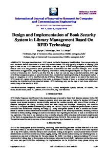
3.5.3 The ray casting method Another way of finding whether the point is inside or outside a simple polygon is to test how many times a ray starting from the point intersects the edges of the polygon. If the point in question is not on the boundary of the polygon and the number of intersection points is even, then the point is outside otherwise it is inside. This algorithm is also known as the crossing number algorithm.
31
Figure 3.7: The grid method; the cell corner classified as outside but the point is inside (Antonio and David, 1992).
Figure 3.8 shows two points A and B in a polygon. The ray cast from point A forms three intersection points with the polygon and therefore it is inside. The ray cast from point B forms two intersection points with the polygon and therefore it is outside. The algorithm is based on a simple observation that if a point moves along a ray from infinity to the probe point and crosses the boundary of a polygon, possibly several times, then it alternately goes from the outside to inside, then from the inside to the outside. As a result, after every two "border crossings" the moving point goes outside (Petker, 2010). This observation may be mathematically proved using the Jordan Curve Theorem.
32
Figure 3.8: The ray casting method; point A is inside but point B is outside the polygon (Sutherland, 1974).
When implemented on a computer with fine precision arithmetic‟s, the results may be incorrect if the point lies very close to that boundary because of rounding errors. This is not normally a concern, as speed is much more important than complete accuracy in most applications of computer graphics (Sutherland, 1974). Due to its high speed in determining whether the point is inside or outside the polygon, the ray casting method is used in this work.
This is a two dimensional problem and so a point is described as a pair of coordinates: x and y. A polygon is as an array of points describing the vertices (the corners) of the polygon. The sides of the polygon are the lines drawn between successive vertices in the array. We can assume that the polygon is closed (that is, an edge is also drawn from the final point in the array to the first). To define a valid edge intersection, rays are shot only in the positive x-direction. In that case, each ray shot from a point
P , P separates the (x, y) plane into two regions: The region R1 x
y
containing all the points p x , p y such that p y Py ; and the region R2 containing all
33
the points p x , p y such that p y Py . The intersection counter is incremented only if the two endpoints of an edge lie in different regions and if the intersection points of the edge with the line y = Py lies to the right of P.
The figure 3.9 shows the region changes of edges ei with respect to a ray r. a) e1 does not intersect because the intersection point is to the left of P. b) e2 does intersect because both ends are in different regions. c) e3 does not intersect because both endpoints are in the same region. d) e4 does intersect because the endpoints are in different regions. e) e5 does not intersect because both endpoints are in the same region.
Figure 3.9:The region changes in edges ( ei ) with respect to a ray( r) (Glassner, 1989).
3.5.3.1 The ray casting algorithm a) From the point (x, y) in question, shoot a ray (half-line) in the positive xdirection as shown in figure 3.10. b) Initialize a counter intersection count to zero. c) For each edge (e) of the polygon defined by (x1, y1) and (x2, y2) check the following:
34
If y1