1
Design and Fabrication of Heat Storage Thermoelectric Harvesting Devices M. E. Kiziroglou, Member, IEEE, S. W. Wright, T. T. Toh, P. D. Mitcheson, Senior Member, IEEE, Th. Becker and E. M. Yeatman, Fellow, IEEE Abstract — Thermoelectric energy harvesting requires a substantial temperature difference ΔΤ to be available within the device structure. This has restricted its use to particular applications such as heat engine structural monitoring, where a hot metal surface is available. An alternative approach is possible in cases where the ambient temperature undergoes regular variation. This involves using a heat storage unit, filled with a phase change material, to create an internal spatial temperature difference from the temperature variation in time. In this paper, the key design parameters and a characterisation methodology for such devices are defined. The maximum electrical energy density expected for a given temperature range is calculated. The fabrication, characterisation and analysis of a heat storage harvesting prototype device is presented for temperature variations of a few tens of degrees around 0 °C, corresponding to aircraft flight conditions. Output energy of 105 J into a 10 Ω matched resistive load, from a temperature sweep from +20 °C to -21 °C, then to +25 °C is demonstrated, using 23 g of water as the phase change material. The proposed device offers a unique powering solution for wireless sensor applications involving locations with temperature variation, such as structural monitoring in aircraft, industrial and vehicle facilities. Index Terms— energy harvesting, thermoelectric, heat storage, phase change materials, PCM, avionics, wireless sensor networks
I. INTRODUCTION Wireless sensor networks are revolutionizing the means of monitoring in applications such as human health, vehicles, machines and production plants [1, 2]. In order to eliminate wiring, the standard sensor powering solution is the use of batteries, which require accessibility and periodic replacement or recharging. This is impractical for applications involving sensor locations that are difficult to access. A promising alternative to manual recharging is energy harvesting, which uses ambient energy, in the form of relative motion, heat flow, light or electromagnetic radiation, to deliver useful power to a wireless system such as a sensor Manuscript received June 30, 2012; revised November 09, 2012; accepted March 09, 2013. Date of publication … Copyright (c) 2009 IEEE. Personal use of this material is permitted. However, permission to use this material for any other purposes must be obtained from the IEEE by sending a request to
[email protected]. M. E. Kiziroglou, S. W. Wright T. T. Toh, P. D. Mitcheson and E. M. Yeatman are with the department of Electrical and Electronic Engineering, Imperial College London, SW7 2BT, U.K. (e-mail:
[email protected]) Th. Becker is with Electronics and Systems Integration, EADS, Germany
node. Depending on size, energy source and application, the output power for energy harvesting devices is typically in the range between microwatts and hundreds of milliwatts [3]. Reviews can be found in the literature for motion, thermoelectric and light energy harvesting [2, 4-7]. Various thermoelectric generator (TEG) energy harvesting devices have been proposed [4, 8], and some have been commercialised, such as the Seiko Thermic wrist watch [9] and the Micropelt generators [10]. The thermoelectric materials used in these implementations are telluride alloys, which typically give a dimensionless figure of merit ZT, of around 0.8, at room temperature. ZT is defined as [4]:
ZT
a2 T Re K
(1)
where Re is the electrical resistance, K the thermal conductance, a the Seebeck coefficient (defined as the open circuit output voltage per Kelvin of temperature difference), and T the average temperature of the thermocouple. The theoretical maximum efficiency of a TEG, ηTEG, can be written as a function of ZT and the temperature difference ΔT = Th Tc between its hot (Τh) and cold (Tc) surfaces [11]:
1 ZT 1 T (2) Tc Th 1 ZT Th For ZT=1, the theoretical efficiency of such telluride alloy TEGs operating at e.g. ΔΤ = 20 Κ and close to room temperature, is about 1%. This demonstrates the fact that conversion efficiency in thermoelectric harvesting is intrinsically low and highly dependent on the available ΔΤ. Alternative thermoelectric materials have been shown to give higher ZT values. Telluride superlattice thermocouples with ZT as high as 2.5 have been demonstrated [12], corresponding to 2% efficiency at ΔΤ = 20 Κ close to room temperature. The vast majority of TEG devices operate where a spatial temperature difference naturally exists across the device in the environment in which the generator is located, for example between a hot machine and a colder ambient. However, an alternative approach has recently been proposed [13-15], in which a heat storage unit (HSU) is employed to transform a temperature variation in time into a spatial difference ΔΤ, which can then be exploited by a TEG. A material that changes phase within the ambient temperature variation range (phase change material, PCM) is used in the HSU to achieve a large energy storage density, as well as to maximise the average temperature difference. Two prototype devices for
TEG ()
2
The operating principle of heat storage thermoelectric harvesting can be described with reference to the device reported in this paper, which is illustrated in Fig. 1. The HSU comprises a PCM inside a container which provides thermal contact to one or more TEGs and is otherwise thermally insulated from the environment. The PCM-TEG thermal properties are enhanced by a bridge structure which improves the temperature uniformity within the PCM. An insulation layer prevents heat leakage to the environment through the rest of the HSU surface. A finned heat sink is used on the outside TEG surface, to improve the thermal contact with the environment. When the environmental temperature fluctuates, heat flows in and out of the HSU through the TEGs, resulting in generation of electrical energy. The energy output of the harvesting device can be collected, stored and distributed by a power management system. Insulation Metal Container Phase Change Material
Tin Q
ΔΤ Source
Thermal Contact
Thermal Contact
Thermoelectric Generator
Thermoelectric Generator
Thermal Contact
Thermal Contact
Heat Storage Unit
ΔΤ Source
Features
Thermal Bridges
Environment
Structure
II. DESCRIPTION OF DEVICE CONCEPT
In comparison with conventional thermoelectric harvesters, optimization of performance has a critical difference. In cases where a TEG is used to exploit a local temperature difference directly, the energy source can typically be approximated as a limitless supply of heat at constant temperature, with the input temperature to the TEG affected only by the finite thermal conductance of the source structure, not by the loss of energy through the TEG. Consequently, maximisation of energy output requires maximisation of the product of heat flow and TEG efficiency. Taking into account the approximately linear variation of ηTEG with ΔΤ, simple calculations show that the TEG thermal resistance should match that of the rest of the thermal path between the high temperature source and the ambient. Thus optimum operation in direct thermoelectric harvesters occurs when the temperature difference across the TEG is ΔΤ/2, in analogy with load matching in electrical power transfer. This thermal resistance matching requirement is illustrated in Fig. 2a. On the contrary, in heat storage thermoelectric harvesting the total available heat energy is limited, and hence maximization of conversion efficiency, rather than output power, is required. Consequently, a TEG with as large a thermal resistance as possible is desirable. An electrical analogy of this effect can be found in the discharge of a capacitor into a resistive load, through its own series resistance. As opposed to the case of power transfer from a voltage source where resistance matching is required, in the case of a capacitor discharge, maximization of the load resistance is required. This is illustrated in Fig. 2b. It should be noted that an upper limit to TEG thermal resistance is imposed by the environmental temperature variation period, so that the device manages to fully complete the given temperature sweep. A quantitative discussion of TEG thermal conductivity optimisation was presented in [16].
Lumped Element Model
aircraft applications, exploiting the ambient temperature variation during flights, have previously been reported. Bailly et al. demonstrated 34 J of electrical energy output from a flight cycle temperature sweep from 18 °C to -55 °C and back [13]. Samson et al. showed an energy output of 27 J from a temperature sweep from +20 °C to -22 °C and back [14]. Both devices used 10 g of water as the PCM. In a previous paper, a numerical model of heat storage thermoelectric harvesting devices has been developed and used to study their performance dependence on HSU geometry and TEG thermal conductivity k [16]. It was shown that for a given temperature cycle and device size, the energy output can be maximized by selecting a TEG with an optimum k value. In addition, the importance of phase change was quantified, showing that it typically provides an order of magnitude increase in energy output. In this work, a set of design rules for heat storage thermoelectric harvesting devices is proposed, including a derivation of the maximum output energy density expected from a given TEG and ambient temperature variation. A new prototype device is also presented, and its performance is analysed using analytical expressions and numerical simulation. The results are discussed and areas of interest for further research are identified.
RCONTACTS
RCONTACTS
ΔΤ
ΔΤ Q
RΤEG
Q
RΤEG
ΔΤ: Constant
ΔΤ: Varying
Q: Practically Infinite
Q: Limited by HSU capacity
Optimisation: max Q•η ~ Q•ΔΤTEG
Optimisation: max η ~ ΔΤTEG
RTEG = RCONTACTS
RTEG = max
Thermoelectric Generator Heat Sink To Environment
Tout Fig. 1: Schematic of the device structure.
(a)
(b)
Fig. 2: (a) Direct thermoelectric harvesting. Heat availability is practically unlimited and optimum operation requires thermal resistance matching. (b) Heat storage thermoelectric harvesting architecture. Maximum thermal resistance is required.
3 III. DESIGN CONSIDERATIONS
IV. THEORETICAL ANALYSIS
In order to design a device for a particular application, a group of key parameters must be considered. The nature of the application will determine the temperature cycle characteristics, namely the temperature range, rate of change and cycle period. In the selection of the PCM, phase change within the available temperature range must be ensured. The specific heat capacity cp and phase change energy EPC should be maximized, and a sharp phase change is desirable. High thermal conductivity k is required to minimize temperature gradients within the PCM. For this purpose, additives to enhance k or thermal bridge structures may be essential. The PCM container structure must provide good thermal contact between the PCM and the TEG unit, and minimise simultaneous heat leakage to or from the environment through non-TEG paths. Thus, minimisation of the HSU surface area that is not covered by TEGs, and the use of highly insulating materials such as polyurethane foam or polystyrene, are required. Internally, the container may include a heat sink structure as a thermal bridge. In addition, it is desirable that the internal surface is such that it does not induce phase change nucleation, which may lead to non-uniform PCM freezing. Finally, as discussed in above, a TEG with low thermal conductivity kTEG is desirable. In particular, kTEG should be much lower than the thermal conductivities of the PCM and the heat sinks/bridges, to maximise the ΔΤ that is applied across the TEG. Furthermore, depending on the ambient temperature cycle profile, a low kTEG is beneficial as it increases the time lag between exterior and interior temperature change, and so increases T. However, kTEG should be substantially higher than the thermal conductivity of the insulation used, to minimise the loss through heat leakage, and high enough to ensure a complete phase change cycle within the temperature cycle period. The geometry of the TEG and the HSU, particularly their thicknesses, must be taken into account in the calculation of suitable k values. The desirable characteristics of each constituent part of the device are summarised in Table 1.
In this section, a theoretical model for heat storage thermoelectric harvesters is developed with the following simplifying approximations:
TABLE I SUMMARY OF DESIRABLE DEVICE PROPERTIES Device Part Phase Change Material Heat Storage Unit ThermoElectric Generator
Desirable characteristics High heat capacity cp High latent heat EPC Phase change within temperature range High thermal conductivity Minimised super cooling High k of PCM – TEG thermal interface Low k insulation Low insulation area to TEG area ratio Thermal bridge for kPCM enhancement High efficiency at low ΔΤ kTEG > kHSU insulation kTEG small, to maximise TPCM delay kTEG high enough for full phase change
The temperature inside the HSU is uniform Only the PCM contributes to heat capacity Thermal conductivities are independent of temperature
If R is the thermal resistance between the interior and the exterior of a HSU with heat capacity C and latent heat L, then during non-phase change operation, the heat inside the HSU Q and the heat flow Q will be:
Q C Tin
(3)
T Q R
(4)
where ΔT = Tout - Tin is the difference between outside and inside temperatures. Combining (3) and (4) gives a differential equation for ΔT, for non-phase change operation:
T
T Tout RC
(5)
For linear time variation of Tout, i.e. Tout ሺtሻ=b·t+Tout (0ሻ, an analytical equation for ΔT during non-phase change (NPC) operation can be derived:
T (t ) NPC T (0) et / RC b RC (1 et / RC )
(6)
The first term on the right side of (6) corresponds to the exponentially decaying T that would result from an initial temperature difference; the second originates from the Tout change, and approaches the limit b·RC. During phase change operation, Tin is constant, and therefore ΔΤ is the sum of any initial condition ΔΤ(0) and the variations in Tout:
T (t ) PC b t T (0)
(7)
From the above equations, analytical expressions for heat, heat flow, and HSU temperature can readily be derived. To find the total electrical energy Eout produced by the TEG, heat leakage must be taken into account. If δ·Qሶ is the portion of Qሶ that flows through the TEG, then:
Eout Q TEG dt T (t ) TEG dt R
(8)
Here, the use of equation (2) for the TEG efficiency should be discussed. During operation, the Seebeck and ohmic effects of a thermocouple affect the heat flow at the hot junction such that for a TEG current I [11]: (9) Q h K a h I 12 I 2 Re Under typical operating conditions, these phenomena increase the effective heat conductivity of the device. The TEG efficiency is defined as electrical output power over
4 thermal input power (I2 ·RL /Qሶ h ), where RL is the resistive load connected to the TEG. Defining the resistance ratio μ = RL/Re, the following general expression for ηTEG can be written: TEG
Th ( 1) 2 / h ( 1) / 2Th
(10)
The maximum efficiency is obtained for μ=ඥ1+ΖΤh , yielding (2). This optimum point is different from the maximum power delivery point for a TEG, which is obtained for μ = 1. For ZT values around 1 and TEG ΔΤ around 30 οC, the corresponding efficiency difference is approximately 6%. However, this difference becomes more substantial for higher ΖΤ and ΔΤ values and should be taken into account in the design and characterisation of TEG devices. The ZT and ΔΤ values expected for the cases presented in this paper correspond to efficiency differences less than 5% due to this effect. Therefore, device characterisation is performed with load matching and the corresponding power output can be written as: POUT
(V / 2) 2 a 2 2 Re 4 Re
(11)
It is shown in section IX that the extraction of an effective value for the Seebeck coefficient is possible from this equation, offering a more direct quantification of the performance of such devices. V. MAXIMUM POSSIBLE OUTPUT ENERGY The maximum energy that can be harvested from a heat storage device can be calculated, for a given ambient temperature sweep, from the total available heat energy and the maximum possible TEG efficiency. For this calculation, zero heat leakage (δ = 1) and a linear approximation of (2) for ηTEG is used: TEG ( T ) T
(12)
Combining (8) and (12) gives Eout
R
T (t ) 2 dt
(13)
If an HSU is exposed to an ambient temperature change from Tmin to Tmax (= Tmin + Θ) and back (one full cycle), the heat energy exchanged between the HSU and the ambient during each half cycle will consist of the temperature change energy Θ·C, where C is the PCM heat capacity, and the PCM latent heat L. The total heat energy exchanged is thus:
Eheat 2 [ C L]
(14)
It should be noted that Θ is, by definition, the total change in time of the ambient temperature, and should not be confused with ΔΤ which is the temperature difference across the TEG. It is assumed that the heat capacity C is constant, that phase change occurs within the given temperature cycle, and that enough time is provided so that the PCM reaches the upper and lower values of the temperature cycle, i.e. reaches steady state.
Higher ΔΤ values are obtained for an abrupt Tout profile, such that Tout instantly switches from a minimum Tmin to a maximum Tmax and subsequently back, with enough time between transitions (to) for Tin to stabilize. Such a profile offers maximum efficiency and output electrical energy for a given Θ. Regardless of when the phase change occurs in such a temperature cycle, the ΔΤ at which the (non-latent) heat energy Θ·C will be transformed will be determined by the first term of (6), as Tout is constant and hence b = 0, and ΔΤ(0) = Θ. Therefore, the maximum energy that can be harvested from the non-latent (NL) heat of each half cycle will be:
Ee , NL
to
R 0
T (0) 2 e 2t / RC dt
for to >>RC. This gives: Ee , NL
2 RC R
2
C 2 2
which, using equation (12), can be written as:
Ee, NL C TEG 2
(15)
The physical meaning of this result is that the maximum efficiency during the transformation of the non-phase change heat energy is ηTEG(Θ/2). In other words, the maximum possible average ΔΤ during non-phase change is half the total available temperature range Θ. If ΤPC is the phase change temperature, then the latent heat energy L will be transformed at a ΔΤ = Τmax - TPC during the first half cycle and at ΔΤ = ΤPC - Tmin during the second half cycle. This gives, again, an overall average of Θ/2. Therefore, the maximum electrical energy that can be harvested from latent heat during a full cycle is: E e, L 2 L TEG 2
(16)
In conclusion, the maximum energy that can be harvested by a heat storage thermoelectric harvester of heat capacity C and latent heat L, from an ambient temperature cycle of change Θ, is the sum of (15) and (16): E MAX 2 ( C L ) TEG 2
(17)
Thus the overall maximum efficiency is simply the TEG efficiency for Θ/2. Equations (12) – (17) were used to calculate the maximum electrical energy per unit mass of heat storage material available from a thermoelectric generator. The simulated results using (2) and (17) are plotted in Fig. 3 as a function of ambient temperature variation, for different TEG figures of merit, using L/m = 334 kJ/kg, and C/m = 4.2 kJ/(K-kg), where m is the PCM mass. Water was chosen as the PCM because its heat storage properties are superior to other heat storage materials which are typically salt-based or organic solutions.
5 coefficient a0 = Vopen / ΔΤ for a given device. This coefficient can then be used along with other device parameters to predict performance for various ambient temperature profiles. This method will be used to analyse the performance of the prototype device presented in the following sections.
50 Maximum Possible Electrical Energy (J/g)
ZT = 3 ZT = 2 ZT = 1
40
ZT = 0.5 Device Sim.
VII. DEVICE FABRICATION
Device Meas.
30
20
10
0 0
20
40
60
80
100
Ambient Temperature Variation Θ = Tmax - Tmin (K) Fig. 3: Electrical energy per PCM mass versus ambient temperature variation, for TEGs with various figures of merit ZT. The measured performance of the device presented in this paper is shown by the square marker.
VI. NUMERICAL MODEL While analytical equations for temperatures, ΔΤ, heat and electrical output can be calculated from the above analysis, the solutions are of different form for heat flow during phasechange and non-phase-change operation. It is therefore more practical to implement the solution numerically. During non-phase-change, the combination of (2) and (3) gives ܶሶin = ΔΤ/RC. During phase-change, Tin is constant. To determine heat flow, (4) can be applied in both modes. In a discrete formulation, from any state of the system [Tin(n), Tout(n), Q(n)] the next state [Tin(n+1), Tout(n+1), Q(n+1)], after a time step Δt, can be calculated using the following equations: t Tin (n) (Tout (n) Tin (n)) RC (non - phase change) Τ in(n 1 ) (phase change) Tin (n)
Q(n 1 ) Q(n) (Tout ( n ) Tin ( n )) t/R
(16)
(17)
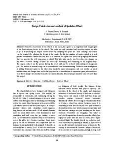
The harvester HSU comprises a custom-made aluminum alloy (Dural) waterproof container, 23 g of distilled water as PCM and a thermal insulation box. The metal container has outer dimensions 60 × 30 × 30 mm, 2 mm thick walls and includes two internal thermal bridges to improve temperature homogeneity. Its mass is 65 g and its internal volume is 30 cm3. Sealing is achieved by a gasket sealant applied between the box and a lid which is secured by screws. A hotwire shaped extruded polystyrene box with 2 mm thick walls is used for insulation. Two off-the-shelf TG12-2-5 Marlow Industries Inc. TEGs were used. Each has a size of 30×34×4 mm, with thermal resistance of approximately 3.6 K/W, corresponding to a thermal conductivity of 1.1 W/m·K. The figure of merit ZT and series resistance of each TEG are 0.72 and 5 Ω (±10%) respectively, as quoted by the manufacturer. This was confirmed by TEG impedance measurements, which demonstrated a resistive behaviour with a change of 10% over the temperature range investigated during operation. The TEGs were attached to the Al container surface by thermal grease. Photographs of the container and the assembled device are shown in Fig. 4. Measurements were performed by applying a temperature sweep profile to the surrounding environment. During tests, the device was positioned inside a chamber for the coolingdown phase and removed for the warm-up phase. A diagram of the test setup is shown in Fig. 5. The environmental and PCM temperatures were monitored using type-T thermocouples. The two TEGs were electrically connected in series and their combined output was connected to a 10 Ω load, matching their internal resistance. The voltage across the load was monitored during the temperature sweep. Thermal Bridges TEGs
For any given ΔΤ(n), the corresponding η(n) can be calculated from (2). Using (4), the electrical power output can be calculated, giving: (18)
m
m m mm
m
30
64
The system comprising equations (16) - (18) are used in the analysis of experimental results. Device parameters such as the time constant RC, heat resistance R, and average ΖΤ can be extracted by fitting the simulations to experimental measurements. The overall RC of a device, including heat leakage, can be determined directly by fitting (16) to Tout and Tin measurements. A link between R and L can be obtained from the measured duration of phase change. Finally, the conversion efficiency can be derived by fitting measured voltage data as a function of ΔΤ, to obtain an effective Seebeck
Insulation 30 mm
60
T (n) Tim (n) (n) Pout (n) Q (n) (n) out R
Al container
34
mm
Fig. 4: Photographs of the heat storage thermoelectric harvester. Left: metal container with lid removed, showing the two thermal bridges. Right: assembled generator. The metal container is partially raised for visibility.
6 100
80
TC
TIN Logger
Voltage Logger
10 Ω
TEGs Cooling Stage
TC
TOUT Logger
Fig. 5 Test setup used during experiments.
VIII. EXPERIMENTAL RESULTS Data provided by Airbus [17] shows that, in typical flights, the temperature variation of the aircraft skin is between +20 C and -20 °C, with a rate of change of 3 K/min [17]. Therefore, the heat storage harvester presented here was tested under similar conditions. A temperature profile and the corresponding device response are presented in Fig. 6. The corresponding power and energy, calculated from the voltage measured across the 10 Ω load, are shown in Fig. 7, along with an inset of the simulated thermal image of the device warming up. Starting from +20 °C, Tout is reduced to -14 °C at a rate of 2 K/min (min 0 to min 18 in Figs. 6 and 7). As expected, the HSU internal temperature Tin follows the temperature drop with a delay, resulting in a ΔΤ of around 10 Κ, giving an output voltage of up to 0.4 V. However, instead of remaining constant during phase change at 0 °C, Tin continues to decrease to -9 °C and then increases abruptly to 0 °C. This effect was attributed to the water experiencing super-cooling, and it is undesirable because it results in a period of low ΔΤ and hence low transduction efficiency. As shown in Fig. 7, the energy output from this interval is around 9 J. Following this super-cooling period, phase-change operation occurs. Phase change operation occurs at ΔΤ = -14 °C, providing a stable voltage output of 0.4 V for around 10 minutes (min 19 to min 29 in Figs. 6 and 7). The corresponding energy output from the phase change is 13 J. At the end of phase change, Tin continues to decrease towards Tout, yielding another 5 J of electrical energy (min 30 to min 35 in Figs. 6 and 7). 25
1 Tout Tin Vout
Temperature Profiles / oC
15
0.8 0.6
Tin,Sim
10
0.4
5
0.2
0
0
−5
−0.2
−10
−0.4
−15
−0.6
−20
−0.8
−25 0
10
20
30
40 50 Time / min
60
70
Voltage on 10 Ω load / V
20
−1 80
Fig. 6: Measured instantaneous temperature and output voltage, and simulated internal temperature, for a temperature cycle between + 25 °C and -20 °C.
Electrical Power / mW
Harvester
150 Power Energy Energy,Sim
120
60
90
40
60
20
30
0 0
10
20
30
40 50 Time / min
60
70
Total Electrical Energy / J
Cooling Chamber
0 80
Fig. 7: Instantaneous electrical power output and energy corresponding to the Vout measurements of Fig. 6. Simulation results for the energy and a thermal image (inset) of the warming up phase are also shown.
The system then slowly drifts towards -21 °C. No substantial energy output appears from this slow change, as ΔΤ is just a few K (min 36 to min 52). Subsequently, Tout is raised to +22 °C at an average rate of 5 K/min (min 53 to min 61), and is then left to fluctuate around +25 °C. During heating, phase change begins at Tin = 0 °C as expected. Tin stays in the range 0 – 6 °C for around 10 minutes. Phase change occurs at a ΔT of around 20 °C, giving a voltage output as high as 0.9 V. The harvester yields 45 J of electrical energy during this 10 minute phase change. The overall energy from this temperature cycle is 105 J, 98% of which is supplied at a voltage higher than 0.2 V. From (10), and using the average heat properties of water for this temperature range (liquid heat capacity 4.2 kJ/(kg·K), solid heat capacity 2 kJ/(kg·K) and latent heat 334 kJ/kg), the total heat exchanged by the PCM during this temperature cycle is calculated to be 21 kJ. The total heat passing through the HSU also includes that from the Al (0.897 kJ/(kg·K)), yielding a total of 26 kJ. Hence, the overall efficiency of the harvester is 0.4%. IX. DISCUSSION Further information regarding the performance of this device can be obtained using the simulation model introduced in section VI. The Tin profile calculated from (16) using the measured Tout profile as input is plotted in Fig. 6. No parameter fitting was performed for this calculation. All parameters were specified independently; for heat capacity the aforementioned heat properties for water and Al were used. The overall HSU resistance was determined as the total heat resistance of the two TEGs. During non-phase change operation, good matching to the experimental curve is observed, indicating that heat leakage and other parasitic device effects are negligible. During the first phase change, substantial deviation is seen, which could be due to water super-cooling (see section VIII). Similarly, a temperature drift during the heat-up phase change is apparent in the measurements, which is not captured by the model. It is evident from the graph that both these effects reduce ΔΤ during phase change and consequently reduce the generated
7
25
0.8
T
in
0.6
Vout
10
0.4
5
0.2
0
0
−5
−0.2
−10
−0.4
−15
−0.6
−20
−0.8
−25 0
10
20
30
40 50 Time / min
60
70
Voltage on 10 Ω load / V
15
−1 80
Fig. 9: Simulated device performance expected from a typical full flight temperature cycle: instantaneous values of temperatures and voltage output.
100
150 Power Energy
1 0.8
1 Tout
20
Temperature / oC
voltage. The corresponding simulated energy output is shown in Fig. 7. A plot of the measured TEG voltage output of Fig 6 as a function of ΔΤ is given in Fig. 8. A linear correlation is observed, suggesting a constant effective Seebeck coefficient in this temperature range. Fitting of the gradient of this plot yields 42 mV/K (±1 mV/K) for two TEGs connected electrically in series (with a matched load). This corresponds to an open-circuit voltage of 42 mV/K for each TEG. As not all of the measured ΔΤ is actually applied across the TEGs, this coefficient should not be interpreted as a strict characteristic of the TEGs used, but can be regarded as an effective Seebeck coefficient of the entire device. For the device presented here, the effective Seebeck coefficient corresponds to a ZT of 0.38 using (1). The same result could be obtained by fitting the measured power curve, using the derivative of (8). This method involves the TEG conversion efficiency and its corresponding expressions. The fitting of voltage rather than power was preferred here as a more direct method. Measurements 42 mV/K linear fit
80
120
60
90
40
60
20
30
0.4 0.2 0
Energy / J
Power / mW
− Voltage on 10 Ω load / V
0.6
−0.2 −0.4 −0.6
0 0
−0.8 −1 −20
−15
−10
−5
0 5 Tout − Tin / K
10
15
20
Fig. 8: Voltage measured on a 10 Ω load vs ΔΤ, extracted from the measurements of Fig. 6. The gradient of the line is 42 mV/K (±1 mV/K).
The experimental determination of the effective Seebeck coefficient allows reliable prediction of performance during other ambient temperature cycles, using the simulation model of section VI. As an example, the device performance for a typical flight temperature cycle with Θ = 40 °C and a temperature sweep rate of 3 °C/min is presented in Figs. 9 and 10. The total output energy is 125 J. The linear V – ΔΤ behaviour illustrated in Fig. 8 means that temperature cycles of the same Θ and rate of change are expected to yield the same energy, regardless of whether they are symmetric around the phase change temperature. By simulating cases of different Θ values and the same temperature change rate, the expected energy output as a function of Θ can be found. For the device presented here, results of this calculation are shown as dots in Fig. 3, for heating and cooling rates of 3 K/min. Energy per unit mass values were calculated here by taking only the PCM mass into account. The measured output is also shown in Fig. 3 for comparison.
10
20
30
40 50 Time / min
60
70
0 80
Fig. 10: Simulated device performance expected from a typical full flight temperature cycle: instantaneous electrical power and cumulative energy.
Effects such as the gradual phase changes of Fig. 6 are not taken into account by the simulations, leading to the simulation overestimating the output energy. In the case shown in Fig. 6, the total energy corresponding to the simulated voltage output is 130 J, while the measured output was 105 J. This suggests a 20% energy loss due to nonuniform phase change and/or super-cooling. Another important conclusion comes from the comparison of the measured energy with the simulation results of Fig. 10. Though the simulated energy output is larger than that measured, the energy measured during the heating phase in Fig. 7 is large, at 80 J. Were this to be achieved in the cooling phase as well, the total produced would be ≈ 160 J, which is substantially higher than the performance anticipated for the temperature sweep of Fig. 10. The reason for this difference is that the temperature change rate during the heating phase in Fig. 6 is much larger than 3 K/min. Indeed, the dashed simulation curve in Fig. 7 gives around 85 J of energy output during the heating phase, close to the measured 80 J. This agreement further supports the possibility that the deviation between simulations and measurements in Fig. 7 is due to nonuniform phase change and water super-cooling.
8 X. CONCLUSION A framework of design and analysis for heat storage thermoelectric harvesting devices has been. The maximum output energy for such devices was calculated as a function of TEG efficiency and ambient temperature change characteristics. As a rule of thumb, a maximum of 10 J per gram of PCM can be expected from state-of-the-art TEGs and expected flight temperature profiles. A novel heat storage harvesting device has been presented, built for powering structural sensors in aircraft wings and fuselages. It demonstrates 105 J of energy output, using 23 g of PCM, from a typical flight temperature profile. Simulation shows that the same TEG technology and device architecture can yield up to 30% more energy, if a more homogeneous and abrupt phase change can be achieved. An assessment of the design implemented in this prototype against the design rules set in Table I reveals that there is substantial room for improvement. In particular, the modification of the PCM properties to avoid super-cooling is foreseen as a way to increase ΔT during phase change, which may lead to energy output increase as high as 30%. An optimum HSU geometry for heat leakage minimisation could allow the use of thinner insulation. Finally, the TEGs were of substantially higher thermal conductivity than the optimum, reflecting the fact that TEGs with lower k than the current state-of-the-art are desirable. The results of this work demonstrate that heat storage thermoelectric harvesters can provide sufficient energy for devices such as wireless sensor nodes, with reasonable device sizes. In the experimental case presented, if the generated energy of 105 J was fully used during the 80 minute cycle, the average available power would be 22 mW. The use of temporal rather than spatial temperature gradients relaxes installation location restrictions, opening up possibilities for battery-less wireless sensor networks in avionics and industrial electronics.
[5]
[6]
[7]
[8]
[9]
[10]
[11] [12]
[13]
[14]
ACKNOWLEDGEMENTS This work has been supported by the Clean Sky JTI under the theme JTI-CS-2010-1-SFWA-01-016.
[15]
REFERENCES [1]
[2]
[3] [4]
V. C. Gungor and G. P. Hancke, "Industrial Wireless Sensor Networks: Challenges, Design Principles, and Technical Approaches," IEEE Trans. Ind. Electr., vol. 56, pp. 4258-4265, Oct 2009. Y. K. Tan and S. K. Panda, "Energy Harvesting From Hybrid Indoor Ambient Light and Thermal Energy Sources for Enhanced Performance of Wireless Sensor Nodes," IEEE Trans. Ind. Electr., vol. 58, pp. 44244435, 2011. P. Zeng and A. Khaligh, "A Permanent-Magnet Linear Motion Driven Kinetic Energy Harvester," IEEE Trans. Ind. Electr., vol. PP, pp. 1-1, 2012. N. S. Hudak and G. G. Amatucci, "Small-scale energy harvesting through thermoelectric, vibration, and radiofrequency power conversion," J. App. Phys., vol. 103, p. 101301, 2008.
[16]
[17]
P. D. Mitcheson, E. M. Yeatman, G. K. Rao, A. S. Holmes, and T. C. Green, "Energy harvesting from human and machine motion for wireless electronic devices," Proc. IEEE, vol. 96, pp. 1457-1486, 2008. A. Khaligh, P. Zeng, and C. Zheng, "Kinetic Energy Harvesting Using Piezoelectric and Electromagnetic Technologies-State of the Art," IEEE Trans. Ind. Electr., vol. 57, pp. 850-860, Mar 2010. M. E. Kiziroglou and E. M. Yeatman, "Materials and techniques for energy harvesting," in Functional Materials for Sustainable Energy Applications, E. Kilner, ed, Ed., ed: Woodhead Publishing, 2012. J. P. Carmo, L. M. Goncalves, and J. H. Correia, "Thermoelectric Microconverter for Energy Harvesting Systems," IEEE Trans. Ind. Electr., vol. 57, pp. 861-867, 2010. M. Kishi, H. Nemoto, T. Hamao, M. Yamamoto, S. Sudou, M. Mandai, and S. Yamamoto, "Micro thermoelectric modules and their application to wristwatches as an energy source," in 18th Int. Conf. Thermoelectrics, 1999, pp. 301-307. H. Bottner, "Micropelt miniaturized thermoelectric devices: Small size, high cooling power densities, short response time," 24th Int. Conf. Thermoelectrics, pp. 1-8, 2005. D. M. Rowe, CRC Handbook of Thermoelectrics: CRC Press, 1995. R. Venkatasubramanian, E. Siivola, T. Colpitts, and B. O'Quinn, "Thin-film thermoelectric devices with high room-temperature figures of merit," Nature, vol. 413, pp. 597-602, 2001. N. Bailly, J.-M. Dilhac, C. Escriba, C. Vanhecke, N. Mauran, and M. Bafleur, "Energy scavenging based on transient thermal gradients: Applications to structural health monitoring of aircraft," in PowerMEMS, 2008, pp. 205-208. D. Samson, M. Kluge, T. Becker, and U. Schmid, "Wireless sensor node powered by aircraft specific thermoelectric energy harvesting," Sensors and Actuators A: Physical, vol. 172, pp. 240-244, 2011. D. Samson, T. Otterpohl, M. Kluge, U. Schmid, and T. Becker, "Aircraft-Specific Thermoelectric Generator Module," Journal of Electronic Materials, vol. 39, pp. 2092-2095, 2010. M. E. Kiziroglou, D. Samson, T. Becker, S. W. Wright, and E. M. Yeatman, "Optimization Of Heat Flow for Phase Change Thermoelectric Harvesters," in PowerMEMS, Seoul, Korea, 2011. D. Samson, M. Kluge, Th. Becker, U. Schmid, "Optimization of a Heat Storage Device for an Aircraft Specific Thermoelectric Power Generator," in 8th Europ. Conf. Thermoelectrics, Como, Italy, 2010.
9 Michail E. Kiziroglou (Member, IEEE) obtained his diploma in electrical and computer engineering from Aristotle University of Thessaloniki, Greece, in 2000 and his master in microelectronics and nanoelectronics from Democritus University of Thrace, Greece, in 2003. He holds a Ph.D. in microelectronics and spintronics awarded by the University of Southampton in 2007. He is currently a researcher with the optical and semiconductor devices group of Imperial College London. His research interests include energy harvesting devices, microengineering and energy autonomous wireless sensors.
Steve W. Wright received the BSc degree in Physics and the PhD in Electrical Engineering from Imperial College, London. His research interests have included fabrication methods and properties of compound semiconductor thin film transistors, their use in addressing flat panel displays and integrated drive circuits for displays. More recent work has been on the development of materials and methods for producing high resistance, low TCR materials for high value resistors in integrated circuits, and also high dielectric constant materials for ICs. His current research interests include energy harvesting systems, their associated electronic interfaces and MEMS devices. Tzern Toh received his M.Eng. and Ph.D. degrees from the Department of Electrical and Electronic Engineering, Imperial College London in 2006 and 2011 respectively. His doctoral work focused on a gravitational torque energy harvesting system for continuous rotation sources. Since January 2011, he has been a research associate in the Optical and Semiconductor Devices Group of the same department. Presently, his research focuses on the design of power electronic interfaces for energy harvesting devices deployed in industrial environments. Paul D. Mitcheson (Senior Member, IEEE) received the M.Eng. degree in electrical and electronic engineering and the Ph.D. degree from Imperial College London, U.K., in 2001 and 2005, respectively. He is currently a Senior Lecturer with the Control and Power Research Group, Electrical and Electronic Engineering Department, Imperial College London. He has research interests in micropower generators and their associated power electronics. He is currently investigating adaptive tuning of energy harvesters using switch-mode electronics and optimized interfaces for piezoelectric harvesters. He has a parallel stream of work in wireless power transfer and RF energy harvesting.
Th. Becker graduated (Dipl.-Ing.) in electrical engineering at the University of Bremen, Germany, in 1995 and he received his doctoral level (Dr.-Ing.) for the work on Micro Reactor Technologies in 2000. In 1994 he joined EADS Innovation Works, formerly Daimler Research and Technology, in Munich, Germany. From 2002 to 2004 he has been working as Key Technology Area Manager for Microsystems, Electronics and Microelectronics. In 2004 he has been appointed as Manager for the Gas Sensor Lab and since 2010 he has been appointed as Expert for Autonomous Sensor Systems and has moved to EADS IW in Hamburg, Germany. Since 2003 he is also lecturer for Micro & Nano Technologies at the private University of Applied Sciences of Isny/Germany. In 2008 he became Adjunct Professor in the Physics Department of the same University. Eric M. Yeatman (Fellow, IEEE) obtained his B.Sc from Dalhousie University, Canada, in 1983, and his Ph.D. from Imperial College London in 1989. Since then he has been a member of academic staff in the college's Electrical and Electronic Engineering Department, Optical and Semiconductor Devices Group, currently as Professor of Microengineering and Deputy Head of Department. His research interests include optical and RF MEMS, energy harvesting, and technologies for pervasive sensing. He is Chairman of Microsaic Systems plc, a company developing and marketing compact chemical analysis instruments.