International Journal of Science and Engineering Invention(IJSEI) Volume 02 Issue 03 May 2016, page no. 1 to 12 Available online at www.isij.in
Research Article Access
e-ISSN 2455-4286
Open
Design and Development of Dual Purpose Gear Drive for Blister Machine Application Brijesh Bhavsar1, Prof. Anurag Nema2, Prof. Ketan Dhumal3 1
2
3
M.E. Design Engineering, University of Pune, Pune, Maharastra
[email protected]
Professor (Mechanical Dept.), DPCOE, Pune, India,
[email protected]
Professor (Mechanical Dept.), DPCOE, Pune, India,
[email protected]
Abstract: Blister packaging machine are used by pharmaceutical industry for packing number of product like tablet, capsule, syringes or liquid material. Blister packs are perforated plastic packs useful for protecting product against external factors, such as humidity and contaminations for extended duration of time. Blister packs are portable, can help patients follow drug regimens, and can protect drugs over a long shelf life. Advocates cite several aspects in which blister packaging is better than conventional packaging, including product integrity, product production, tamper evidence, reduced possibility of accidental misuse, and patient compliance. Blister machine consists of many units and subunits. Conveyor is used to carry blister strip in forward direction, on which various operations are performed. One of the operations is printing on the blister strips. It was found that after certain period of time, there was misprinting occurring on Blister strip. To overcome the problem of misprinting, a gear box was developed, which will be synchronized with the conveyor system. This paper present analytical method for designing bevel gears, using Lewis and Buckingham Equations. The developed gearbox perform dual function who’s one output shaft is use to drive conveyor and other is connected to the printing unit. 3D model of gearbox is made using CatiaV5. Static structural analysis of components like gear, shaft is performed using Ansys. Experimental setup is developed to verify the motion is precise and well synchronized. Keywords: Blister Machine, Blister Strip, Lewis and Buckingham Equations. used to drive the roller of the batch printer. After 1. Introduction certain period of time, sagging stretching of belt was Blister strip undergoes various process and observed in the conveyor system. Due to which idler operations within the Blister machine. Out of which pulley need to be repositioned frequently. These one process is to drive the conveyor system, and leads to problem of misprinting of Batch code on the other process is defined exclusively for printing blister packs. It results to inappropriate and batch code on the blister strip. Input power to the incomplete information on the blister strip. To avoid conveyor system is provided using motor. Rollers at it, the operator needs to be adjusting the idler pulley various locations in the conveyor system are driven every time. Therefore now we have arrived to the by belt drive. The batch code printer was attached to solution for the above problem by introducing same conveyor system near to the packaging unit of synchronized and precise motion gear drive. This blister machine. Therefore the same belt drive was gear drive would serve dual purpose, one of its Corresponding Author - Brijesh Bhavsar
Page 1
International Journal of Science and Engineering Invention(IJSEI) Volume 02 Issue 03 May 2016, page no. 1 to 12 Available online at www.isij.in
output shafts will drive the conveyor roller and other of its output shaft will drive the printer unit. By this sagging of belt will not have any effects on batch code printing, and both the process will carry out efficiently. 2. Objective Our main objective is to overcome the problem of misprinting on the blister strip. This can be done by synchronizing two processes i.e. driving the conveyor and other printing process, using single gear drive. The batch printer will be relocated below the conveyor drive. So that slacking or stretching of belt will have no longer effects on the batch printing process. To accompany our objective we will design bevel gearbox having two output shafts. One of the output shafts will drive the roller of the conveyor and other output shaft will drive batch printer. Such that both the process are well synchronized. Motor will be coupled with input shaft of bevel gearbox to transmit required power to both of output shaft. The solution for the above problem was given by selecting dual purpose Gear Drive. The gear drive was selected due to reasons like, Gear drives are less noisy and responds well on different loading, whereas Chain drive worn, breaks easily on impact loading and its maintenance is difficult. In belt drive some adjustment of centre distance or use of an idler pulley is necessary for wearing and stretching of belt drive compensation. Belt drive mechanism has significant uncertainties in determining torsion behaviour as the belt stiffness tends to be nonlinear and highly depended on the belt tension. Therefore Gear drive was selected over belt or chain drives for transmitting synchronized and precise motion to printing unit of the blister machine. The bevel gear box arrangement is made for driving conveyor roller and batch printer of the blister machine. Various design and analysis calculations are justified for the safe design. Mechanical design of components like gears, shafts is done using various theories of failure, selecting appropriate material.
Corresponding Author - Brijesh Bhavsar
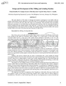
Figure 1: Work flowchart
3. Literature Review In this paper, literature has been critically reviewed involving various studies carried out by various researchers related to the field of designing and analysis of gearbox. Gearbox is an important part of various applications like automobile, hoists, cranes and machines which is used for transmitting different or same torque, power, or speed ratio as per the application. A. A. Pandharabale, Asst. Prof. A. J. Rajguru, [1] The main objective of their paper was to design a model of dual worm system for optimal load lifting capacity, optimal factor of safety and optimal efficiency for reduced power consumption. They have derive the optimal power for individual motor and select the motor for the application so as to make the device compact. The experimental validation part of the lifting force developed by the dual worm system is validated using test-rig. Various characteristics graph were plotted like Torque Vs Speed, Power Vs speed, Power consumption of motor under rated load, Efficiency of system Vs speed. They concluded that the torque increases with the decrease in the output speed, Graph of power output indicates a rising trend up to certain output speed and then slightly drops Page 2
International Journal of Science and Engineering Invention(IJSEI) Volume 02 Issue 03 May 2016, page no. 1 to 12 Available online at www.isij.in
indicating that indicating that the device will slow down slightly if the load is increased. J. D. Chougule1, R. G. Todkar, [2] showed the influence of a cam shaft in the transmission system of a blister packaging machine used for packaging of tablets. It is observed that the cam shaft fails due fatigue loading into two pieces during operation. To find out cause of failure, a finite element analysis was carried out. Results of stress analysis reveal that the highest stressed area coincides with the fractured regions of the failure of the shaft. The theoretical stress fairly matches with the sub-model stress values. The failure analysis shows that the fatigue failure of the shaft is due to weak section at the step provided for cam shaft mount. To enhance service durability of the transmission system of Blister Packing Machine, stress concentration at cam step was modified and material with high service durability, mechanical characteristics such as fatigue strength, ultimate tensile strength, and fracture toughness was selected. Ashish N. Taywade, Dr. V. G. Arajpure, [3] Their paper deals with the idea of gear designing and development for automobile application. Basically the driver and driven gear material plays vital role for the better performance in wear. Replacement of metal gears by plastic gear is continuing in automobiles, appliances and machinery due to its merits of low noise, less wear, self lubrication, economical considerations, light weight, simple design and manufacturing. Due to thermal wear acetal gear failed, so to overcome the problem of acetal gear, nylon 66 material was selected. They concluded that, the nylon 66 is better option due to its superior properties and it also meets extreme performance challenges. S.S. Kachare, R.M. Ghodake and V.D. Ghogare, [4] Have focus their work on Tracked vehicles which are equipped with Hydraulic drum type winch. The main function of winch is to carry out self recovery of the vehicle, limited recovery of the other vehicles and assisting in amphibious operations. During the Corresponding Author - Brijesh Bhavsar
self recovery of the vehicle it is proposed that the vehicle speed and the winch speed should be same, for this particular requirement constant speed winch is required. It was required to design and develop two stage dual planetary gear box for 8 tonne capacity winch which will drive the winch drum. The first stage gear pair is a helical and second stage is a planetary where sun is input and carrier will be output, when Ring gear is stationary and fixed to the drum. They emphasise on the fact that in gear design, surface contact strength and bending strength of the gears are assumed to be major contributors for the failure of the gear pair. Therefore bending stress and contact stress are determined using American Gear Manufacturing Association standard to make the design fail safe in bending and pitting failure. Their proposed design focus on reduction of weight and producing high accuracy gears. M. B. Raut, Prof. S. L. Shinde, [5] They have focused their research work in planetary gears. The rim thickness of the annular gear is one of the important parameter of planetary gearbox to meet design objectives. An optimum rim thickness is required to meet the strength criterion at the same time to reduce mass of the gearbox and to save on material cost. Stresses obtained in their design were very less. Further reduction of the annular gear rim thickness was done without hampering the strength of annular gear. In this manner they concluded with optimum rim thickness of the rim for the gear. Nitin Kapoor, Virender Upneja, [6] Their main objective of the paper was to develop parametric model of differential Gearbox by using CATIA-V5 under various design stages. It was observed that Glass filled polyamide composite material was selected as best material for differential gearbox and it is found to be suitable for different revolutions at 2500 rpm, 5000 rpm and 7500 rpm under static loading conditions. Comparisons of various stress and strain results using ANSYS-12 with Glass filled polyamide composite and metallic materials like Aluminium alloy, Alloy Steel and Cast Iron were
Page 3
International Journal of Science and Engineering Invention(IJSEI) Volume 02 Issue 03 May 2016, page no. 1 to 12 Available online at www.isij.in
also being performed and found to be lower for composite material. Dr.L.G.Navale1,N.I.Jamadar,Vaibhav Dhamal,[7] The paper focused on optimization of Spur gear by reducing mass and its effects on Von Mises Stress, Maximum Principle stress, deflection and stiffness of gear by using FE analysis. There study also represents vibration response of gear by considering harmonic response. The design of gear and stresses on gear were calculated using the Lewis equation and then analyzed with the FE model. Their spur gear train shall be used in Greaves diesel engine. Pradip B. Adake, Amol N. Patil, [8] Carried out work regarding the determination of true bending stresses in spur gears. Loads were applied along the top face at equal distances. The results of bending stress were obtained using Ansys and Kisssys software packages. Kisssoft results were in well agreement with those obtained by analytical method. Keeping the load per unit thickness of the gear constant and the analysis is repeated for various tooth thicknesses of the gears. Also they carried out load variation to study the effect of load on bending stress & deformation. They concluded from their studies that the bending stress is not constant throughout the thickness of the gear, if load per unit thickness is kept constant than maximum stress are nearly same for all thicknesses and lastly as the loads increases, the bending stress increases i.e. the bending stress are directly proportional to the applied load. 4. Blister Machinery Process The sequence of Blister Machinery Process involves heating the plastic, thermoforming it into blister cavities, loading the blister with the product, placing lidding material over the blister, and heat-sealing the package. This can be a simple manual process, or it can be partially or fully automated. Although purchasing empty, preformed blisters and lidding material and then filling the product in a separate step is possible, this is rarely done. Instead, the package is created and filled on the same machine. [10] Corresponding Author - Brijesh Bhavsar
Figure 2: Blister Strip Packaging
Figure 3: Detail Assembly of Blister Machine 4.1 Detail Assembly of Blister Machine The essential parts and functions of an intermittently operating packaging machine include the following. The unwinding station: The unwinding station supplies the forming films and the lidding material at a rate corresponding to the speed of the packaging machine. The heating station: The heating station raises the temperature of the plastic forming films to a level suitable for deep drawing. Forming films containing the polyvinyl chloride (PVC) support material are heated to 120–140 C. Polypropylene (PP) forming films are heated to 140–150 C. Forming films containing aluminium are not heated before the forming process. The forming station: The forming station forms the plastic blister cavities via compressed air or die plates. Films containing aluminium are formed with mechanical forming tools only. The feeding machine: The loading area fills the blister cavities Page 4
International Journal of Science and Engineering Invention(IJSEI) Volume 02 Issue 03 May 2016, page no. 1 to 12 Available online at www.isij.in
with product. The feeding machine can be linked, or the product to be packaged can simply be swept into the blisters. The sealing station: The sealing station heat seals the lidding material to the forming film that contains the product. All heat-sealing methods mate the blister and lid under constant pressure for a specified time, during which heat is supplied. The mating surfaces fuse and bond, setting almost instantaneously when heat input stops. Depending on the type of machine, the sealing temperature typically ranges between 140 and 340 8C. Labelling and Packaging: Packages are labelled, notched, and then marked with a batch number at the coding station. The perforating device makes a cross-shaped perforation along the sealing seams. At the punching station, the packages are then separated into sheets that typically contain from 10 to 20 individual blisters. The vision system checks the filled packages for defects. Finally, a multi packing machine packs the individual packages into bigger cartons. Printing process: The printer unit is simple & low cost coders are ideal for continuous coding on various packaging machines. The message to be printed is very easily composed by just assembling the stereos (easily changeable) on to the print drum. The Inking system consists of a rechargeable circular cartridge, which is fully enclosed allowing the use of fast-drying & indelible solvent-based inks for porous and non-porous surfaces. The whole assembly is directly mounted on the packaging machine with the supplied bracket & as the film passes over the roller of the bracket, it gets printed continuously. [10]
Figure 5: Proposed Setup on Blister Machine 5. Design calculations Gear design is based on Lewis and Buckingham Equations. [9] Material Specifications = En 34 Material Strength = Sb = 330 N/mm2 No. Of teeth on pinion, Z1 = 28 No. Of teeth on Gear, Z2 = 28 Gear Ratio, i = Z2/Z1 = 1 Module, m = 2.5 Pressure angle, φ = 20 Pitch diameter, d = m * Z1 d = 70mm Pitch cone angle, δ = tan-1(Z2/Z1) = 0.7853 rad Cone distance, R = d/(2 sin δ) = 49.497 mm Face Width, b = R/3 = 16.50 mm Addendum, ha = 1 * m = 1 * 2.5 ha = 2.5 mm Deddendum, hf = 1.16 * m = 1.16 * 2.5 hf = 2.917 mm Virtual number of teeths, Zv = Z/ cos δ Zv = 39.598 Lewis form factor, Y = π* (0.154 – 0.912/ Zv) = π * (0.154 – 0.912/ 39.598) = 0.41 Velocity, V = π d N / (60 * 1000) = (π * 70 * 36) / (60 * 1000) = 0.132 m/sec Load carrying capacity of gear tooth or strength of gear tooth is given by, [9] Fs =
Figure 4: Existing Setup on Blister Machine
Corresponding Author - Brijesh Bhavsar
Fs = Fs = 3733.716 N Page 5
International Journal of Science and Engineering Invention(IJSEI) Volume 02 Issue 03 May 2016, page no. 1 to 12 Available online at www.isij.in
Buckingham’s Dynamic load on tooth per unit area is given by, [9] Fd = Cv * Nsf * Km * Ft Now, We want to transmit Power of 0.3 Kw using gear drive. Therefore Force transmitted, Ft can be calculated as follow. Ft = P * (75/V) = 0.3 * (75/ 0.132) Ft = 170.45 N Now, Nsf depends on service factors. Table No 1: Service Factor Coefficient Driven Machinery Source of power Uniform Light shock Medium shock
Uniform Moderate Heavy Shock Shock 1.00 1.25 1.75 1.25 1.50 2.00 1.50 1.75 2.25
We assume driven machine is uniform in nature, therefore Nsf = 1 Table No 2: Mounting Factor Km for Bevel Gears Mounting type Both gears are straddlemounted One gear straddlemounted; the other overhung Both gear overhung
Mounting rigidity 1.0 to 1.25 1.1 to 1.4 1.25 to 1.5
According to our assembly of bevel gearbox we select Km = 1.25 Now For straight bevel tooth Velocity factor, Cv is given by Cv = = Substituting all the values in equation of Stress occurring due to Buckingham’s Dynamic load on tooth per unit area, we get Corresponding Author - Brijesh Bhavsar
Fd = Cv * Nsf * Km * Ft Fd = 1.044 * 1 * 1.25 * 170.45 Fd = 222.43 N According to Lewis and Buckingham Equations, dynamic load on the tooth is less than the strength of the tooth of gear, i.e. Fd < Fs, Our gear is safe in design. P = Fs * V / Cv = (3733.716 * 0.132) / 1.044 P = 471.89 W Torque transmitted at Output shaft is given by T = (P * 60) / (2 π N) = (471.89 * 60) / (2* π * 36) T = 125.17 Nm B. Design of Shaft according to ASME code [1] Material Specification = EN 9 Ultimate Tensile strength = 650 N/mm2 Yield Strength = 480 N/mm2 σs max = 0.18 * σ ult = 0.18 * 650 = 117 N/mm2 σs max = 0.30 * σ yld = 0.30 * 480 = 144 N/mm2 Considering minimum of above values, σs max = 117 N/mm2 Shaft is provided with keyway, which will reduce the strength. Hence reducing the above value by 25 % σs all = 87.75 N/mm2 This is allowable shear stress that can be induced in the shaft material. T = 125 * 103 Nmm Assuming 20 % of overload. T design = 1.20 * 125 * 103 T design = 150 * 103 Now the lowest diameter on output shaft is 50mm, we check Torsional shear failure of shaft, Td * σs act * d3 σs act = (16 * 150 * 103) / (π * 503) σs act = 6.11 N/mm2 Page 6
International Journal of Science and Engineering Invention(IJSEI) Volume 02 Issue 03 May 2016, page no. 1 to 12 Available online at www.isij.in
As, σs act < σs all; Shaft is safe in Torsional load. Now the lowest diameter on intermediate shaft is 40mm, we check Torsional shear failure of shaft, Td * σs act * d3 σs act = (16 * 150 * 103) / (π * 403) σs act = 11.93 N/mm2 As, σs act < σs all; Shaft is safe in Torsional load. Now the lowest diameter on second output shaft is 45mm, we check Torsional shear failure of shaft, Td * σs act * d3 σs act = (16 * 150 * 103) / (π * 603) σs act = 8.38 N/mm2 As, σs act < σs all; Shaft is safe in Torsional load. 5.1 Analysis of Gear and shafts. Gears, shaft along with whole assembly where designed using Catia Software. Each individual component was imported to the Ansys software. Static structural analysis of gears, shafts, is carried out using Finite Element Method software with specific boundary condition.
Figure no 9: Static structural analysis of Output shaft
After carrying out static structural analysis of all the component by using Ansys software, it was found that Gears and shafts are within the safe limit under the loading conditions. 5.2 Experimental Setup: Gears and shaft was made according to the design dimensions. The operations involved in manufacturing gears and shaft were turning, grinding, hobbing, milling, boring. The motor was connected to the input shaft of the gearbox. Motor and input shaft of the gearbox were connected using coupling. The proximity sensors were located at all ends of the shafts. Proximity sensors along with the RPM counter were used to detect the rotation at all the shaft.
Figure no 6: Static structural analysis of Gear
Figure no 7: Static structural analysis of Input
shaft
Figure no 8: Static structural analysis of
Figure no 10: Bevel Gear Assembly
Intermediate shaft Corresponding Author - Brijesh Bhavsar
Page 7
International Journal of Science and Engineering Invention(IJSEI) Volume 02 Issue 03 May 2016, page no. 1 to 12 Available online at www.isij.in
Table No 3: Experimental setup reading Spe ed at Input shaft (RPM )
Figure no 11: Experimental setup for Dual purpose Bevel Gear Drive
A proximity sensor is a sensor able to detect the presence of nearby objects without any physical contact. A proximity sensor often emits an electromagnetic field or a beam of electromagnetic radiation (infrared, for instance), and looks for changes in the field or return signal. The object being sensed is often referred to as the proximity sensor's target. Different proximity sensor targets demand different sensors. For example, a capacitive or photoelectric sensor might be suitable for a plastic target; an inductive proximity sensor always requires a metal target. Make: Wadia Electronics 12mm Dia Inductive Proximity Sensor , sensing - 4mm PNP type , DC i/p- 10-30 V, load current – 200-400mA Can Sense all Metal Object, DC inductive sensor For experiment purpose DC motor drive was used. D.C motors were classified as shunt and series. In addition it was common to see motors referred to as ‘compound-wound’. They reflect the way in which the field and armature circuits are interconnected, which in turn determines the operating characteristics. For example, the series motor has a high starting torque when switched directly on line, so it became the natural choice for traction applications, while applications requiring constant speed would use the shunt connected motor. Corresponding Author - Brijesh Bhavsar
Spee d at Output Shaft2 (RPM)
36
Spe ed at Outpu t Shaft1 (RPM ) 36
Accurac y at output shaft 1 (Percentag e)
Accuracy at output shaft 2 (Percentage )
36
100
100
50 75 85 100
49 75 87 102
50 76 86 100
99 100 98 98
100 99 99 100
The reading was noted down for various speed using proximity sensor and rpm counter. The sensors were connected at the ends of the shaft to not down their speed. It was found that both the shaft was rotating in synchronized manner with respect to Input shaft. Accuracy was achieved in the range of 98 to 100 percentages as shown in table.
Conclusion: The dual purpose gearbox has been designed to transmit torque of 125 Nm at the output shafts, such that conveyor driving process and batch printing process are well synchronized. Analytical calculations for designing bevel gears, is performed using Lewis and Buckingham Equations. Analytical calculations for component within the gearbox like shafts are checked against the limit of stress developed within them and found safe for operations. The developed gearbox perform dual function who’s one output shaft is use to drive conveyor and other is connected to the printing unit. For components like gear and shafts Finite element analysis using software package of Ansys, is carried out and it will be confirmed that gearbox design are within safe limits. Experiment test rig is made to validate the motion for the process is well precise and synchronized. The accuracy of total setup can be further increased by using Servo motor instead of using D.C. motors. This will overcome the problem of misprinting or incomplete printing of batch code on the blister strip. Page 8
International Journal of Science and Engineering Invention(IJSEI) Volume 02 Issue 03 May 2016, page no. 1 to 12 Available online at www.isij.in
References [1] A. A. Pandharabale, Asst. Prof. A. J. Rajguru, Design Development Analysis of Compact Self- Locking Lifting Device by Application of Twin Worm Arrangement, Int. Journal for Scientific Research and Development, Vol. 1, May 2013. [2] J. D. Chougule1, R. G. Todkar, Failure Analysis of Blister Packaging Machine Cam Shaft, IOSR. Journal of Mechanical and Civil Engineering, Vol. 1, No. 6, March 2014, pp. 07-14. [3] Ashish N. Taywade, Dr. V. G. Arajpure, Design and Development of Nylon 66 Plastic Helical Gears in Automobile Application, Int. Journal of Engineering Research & Technology, Vol. 3 Issue 9, September- 2014. [4] S.S. Kachare, R.M. Ghodake and V.D. Ghogare, Design And Development of Two Stage Dual Planetary Gearbox For 8 Tonne Capacity Hydraulic Drum Winch, Int. Journal of Engineering Trends and Technology, Vol. 16 Num. 3, October 2014.
[8] Pradip B. Adake, Amol N. Patil, Determination Of True Bending Stress In Spur Gear By Kisssoft, Fem, Experiment Setup, First Mechpgcon, June 2015. [9] Design Data, PSG College of Technology, Coimbatore, India,1995, pp. 8.4- 8.50 [10] Ron Pilchik, Pharmaceutical Blister Packaging, Pharmaceutical Technology, November 2000, pp. 58-76. Author Profile
Brijesh Bhavsar received the B.E degree in Mechanical Engineering from MET college of Engineering, University of Pune, in 2011. He is now pursuing M.E. in Design Engineering from Dhole Patil College of Engineering, University of Pune.
[5] M. B. Raut, Prof. S. L. Shinde, Investigation Of Effect Of Rim Thickness On Strength Of Annular Gear Of Planetary Gearbox Under Dynamic Conditions, Int. Journal of Engineering Research and General Science, Vol. 2, Issue 6, October-November, 2014. [6] Nitin Kapoor, Virender Upneja, Design And Stress Strain Analysis Of Composite Differential Gearbox, International Journal of Science, Engineering and Technology Research, Vol. 3, Issue 7, July 2014. [7] Dr.L.G.Navale1,N.I.Jamadar,Vaibhav Dhamal, Design and Optimization of Spur Gear Train and Vibrational Response by using FE Analysis, Int. Journal of Current Engineering and Technology, Special Issue-3, March 2014.
Corresponding Author - Brijesh Bhavsar
Page 9