Improved Horn Feed
25-inch (64-cm) Parabolic Reflector Tripod/Mast/Mount
165
a
antenna. Its primary advantage over the sawed-off horn in Figure 11-4 is that the 96-inch (244-cm) parabolic reflector is almost perfectly illuminated in both E and H planes, which will give an additional 1-2 dB gain. Anyone making the effort required to construct a parabolic reflector of this size would do well to spend an additional hour or two to build this feed horn rather than use the modified horn in Figure 11-4. The mounting flange should preferably be of ' / 1 6 -inch (1.5mm) or heavier brass to eliminate any tendency to warp while being soldered. The flange opening, 0.4 inch x 0.9 inch (10 x 23 mm) should be a perfect fit with the Gunnplexer module. Use the Gunnplexer horn antenna mounting flange as a template. This horn antenna design is provided by reference 1. This is the feedhorn antenna to be used for the 96-inch (244-cm) fiberglass parabolic dish now under construction.
ch (64-cm) Parabolic Reflector Tripod/Mast/ Ct 4rr -494 y4zI The world is full of many wonderful things, with a few exceptions. One notable exception is naturally occurring perfect paraboloids made of aluminum with a 25-inch (64-cm) diameter. The Mirro Aluminum Company of Manitowoc, Wisconsin probably has the closest thing to a perfect aluminum 25-inch (64-cm)diameter parabolic dish that is priced at a level most anyone can afford ($6.00 in 1977). A number of microwave antenna manufacturers offer 24-inch (61-cm) parabolic dishes with a few dB more gain than the Mirro dish, but lowest price noted is over $150, which for about 3-dB more gain than Mirrds dish, works out to $50 per dB. That's no bargain at all, so we'll stick to the Mirro marvel. (The Mirro 25-inch (64-cm) dishes are sold by both Sears, Roebuck and Company and J.C. Penney stores: Sears, Roebuck and Company catalog 79N85063L, 25-inch Aluminum Coaster, $6.97 (in 1978). J.C. Penney Company catalog 654003358, 25-inch Snocoaster, $6.99 (in 1978).) As mentioned earlier, these dishes are almost perfect paraboloids, except for the outer 2-inch (51-mm) radius. Because of this departure from a perfect parabolic curve, it's wise to measure the focal point using a Gunnplexer at 10.250 MHz. T o make this
measurement we need a stable mount for the dish. That's why we build the mount first. This tripod mast mount is designed for single-axis azimuth rotation on an antenna rotor mast (but may be modified for elevation rotation too, if desired) and for three-axis adjustment when used with a modestly priced camera tripod.
Materials List for Tripod/Mast Mount 16-inch (41-cm) length of 1 x 3-inch (25.5 x 77 mm) pine 8-95 x 18-inch (22 x 46 cm) sheet of %-inch (6.5 mm) thick double-tempered Musonite four % 20 X 1-95 inch (M6 x 38 mm) nuts, bolts, and washers two 1-95 inch (38 mm) ID U bolts for mast mount six-inch (153-mm) length of yellow pine [ l inch (25.5 mm) diameter broom handle]. ten No. 10 (M5) sheet-metal screws 1-95 inch (38 mm) long and washers The recommended tripod is a Sears, Roebuck and Company 3HA8465 (844.95 each). It's Sear's top-of-the-line camera tripod and is sturdy enough to handle the 25-inch (64 cm) dish and Gunnplexer assembly in modestly high winds if each of the tripod legs is well secured to 8-inch (204 mm) cinder blocks (use masonry nails in the cinder blocks and heavy nylon cord to tie down the ends of the tripod legs. Less expensive tripods will work until the first high wind gusts hit the dish.
Building Frame and Mount The right-hand dish in Figure 11-6shows the H-shaped frame and parabolic-reflector mount. For the antenna rotor and mast mount, a 6-inch (153-mm) square piece of %-inch (6.5-mm) thick Musonite is screwed onto the H-frame rear, with the 1 'h-inch (38-mm) U bolts centered at top and bottom about 34 inch (19-mm) in from the edges. Mount the 6-inch (153-mm) square Musonite plate to the H-frame back, using three no. 10 x 'h-inch (M5 x 38-me0) sheet-metal screws on each side. See Figure 11-7.
166
Building Frame and Mount
Build~ngFrame and Mount
r1/4"16.4 mml TEMPERED MASON1 T E PANEL
/ NO. 10 X I 1/2" (M5 x 3Bmml SHEET META! c r D c w c APCPI 16 PLA,,,,
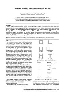
Figure 11-6. Tripod/Mast Mount & 25"D.Parabolic Reflectors The 25-inch (64-cm) diameter reflectors and their tripodfmast mounts. The mounts are made from a Sears, Roebuck and Company camera tripod. Design will withstand modestly high winds if each tripod leg is secured to concrete blocks.
4
The H frame is made from two pieces of 1 x 3 X &inch (25.5 x 77 x 204 mm) pine cut as shown in Figure 11-8. Each of these pieces is notched !4 inch (12.5 mm) deep x %-inch (6.5-mm) wide for the center of the H. which is a 3 x 5 inch (77 X 128 mm) piece of Masonitc. This piece of Masonitc has a %-inch (12.5mm) hole in its center. Mount a U-inch (6.5-mm) sheet-metal washer, with a %-20 (M6) nut brazed or soldered to the washer, over the hole in the Masonitc. Use liberal amounts of epoxy. This washer and nut will be used to attach the assembly to the tripod. The Masonitc center of the H will have a better grip onto the wood sides of the H if the Masonitc edges are drilled '/16 -inch (1.5 mm) deep with a ' / t r -inch (1.5-mm) diameter drill every % inch
1 1/~"(38mrn) U-BOLTS
2 //4"
1
.
Figure 11-7. Antenna Rotor/Mast Mounting- Plate Details for making the antenna rotorlmast mounting plate for the 25-inch cm) diameter Snocoaster parabolic reflectors.
J
(6.5 mm) or so, before being epoxied. Cut four each 1-inch (2. mm) lengths of hard pine broom handle. Drill out the ceni with a 9a-inch (7-mm) diameter drill. Now comes the hard part: Hacksaw a 10-degree angle (fr either flat end) on each piece; or better yet, sand the 10-deg angle with a belt or disc sander. The reason for this bevel is t. we're trying to fit the flat H frame and its plate to the parafn curve of the 25-inch (64-cm) dish without warping or distort its surface when we tighten the mounting bolts. See Fijpre I, The 10-degree beveled edge of the broom handle spacers g against the Masonitc mounting plate, not against the dish.
168
Building Frame and Mount
Building Frame and Mount
DRILL 9/32*(Zlmml DIA.14 PLACES
MEASURED ON BACK OF DISH
9/64*(3.6mml DIA. ( 4 PLACES)
1
SPACERS-BEVELLED ANGLE = 10 DEGREES (SEE TEXT)
Figure 11-9.
Details for the 25-inch (63-cm) diameter dish mounting spacers.
T h e easiest way to lay out the points for drilling the dish-mounting holes is to draw a line between the Snocot hand-hold holes on each side of the dish. Drill out the rivets. a piece of straight %-inch (6.4-mm) thick lath as a ruler sin will bend to fit the dish curve. Draw the line on the back of the dish. Then, with a pl square, lay out a perpendicular line from the center of the dis each side of center that is 3%-inches (89-mm) long upwards 3%-inches (89-mm) long downward. You \?ill now have a pe
170
Building Frame and Mount
Measuring Focal Po~ntof the 25-inch (64-cm) Snocoaster Parabol~cDish
spacing square 7 inches (179 mm) on a side, which is centered on the dish center. Center punch these points and drill the four mounting holes. Now drill the four YM -inch (3.6-mm) diameter holes for the Gunnplexer standoffs. Using the lath as a ruler layout a line from the center of the dish that passes through the center of each hole just drilled. Mark a point 2-%-inches (67-mm) outward past each hole center. Center punch and drill a YM -inch (3.6-mm) hole for the Gunnplexer enclosure standoff mounting bolts. Assemble the dish and mount. Make sure that the spacer beveled angles are positioned as shown in Figure 11-9.
Measuring Focal Point of the 25-inch (64-cm) Snocoaster Parabolic Dish I assume you've built at least one of the Level I Communication Systems presented in Chapter 9 and either have another Gunnplexer or have built the weak-signal source in Chapter 10 to furnish a 10-GHz signal. We'll now set up a mini 10-GHz antenna range and physically vary the distance of our Gunnplexer receiver in its enclosure from the 25-inch (64-cm) parabolic reflector to determine empirically the dish focal point. T h e mini antenna range shown in Figure 11-10 can be assembled and set up in a few minutes. The test bed for sliding the Gunnplexer assembly back and forth is nothing more than two 2 x 4 pieces of lumber about 2-3 feet (0.6-0.9 meter) high that are pounded into the ground, with a piece of 3-foot (0.9meter) long 2 x 4 lumber nailed on top. Adjust the tripod height so that the center of the Gunnplexer horn antenna is dead center with the 25-inch (64-cm) dish reflector. Square everything so that it's either level or on a true vertical. T h e signal source should be located 100-200 feet (30-60 meters) in front of the dish. The less obstructions around the better, as we want to measure the direct signal and not a multi-path signal from the signal source. Typical S-meter readings versuf distance of the Gunnplexer enclosure face from the center of the parabolic dish are shown below on the first run:
(mm) (179) (204) (230) (255) (281) (306) (332) (357) (383) (408) (434) (459) (485) (5 10) (536) (56 1) (765) (867)
inches 7 8 9 10 11 12 13 14 15 16 17 18 19 20 21 22 30 34
S reading (dB over S9) 20 28 27 42 36 29 48 47 43 48 46 44 44 45 46 46 39 38
In this first run three peaks occurred at 13, 16, and 21-22 (352, 408, and 536-561 mm). The latter peaks were cau multipath propagation. T h e signal source was moved f away for lower readings. An average of these runs is:
spacing inches 12 '/8 12 ' 3 6 13 13 1/16 13 !A 16 % 16 7/16 16 !A 16 9/16 16 7 8
(mm)
S reading (dB over S9)
(328) (330) (332) (333) (335) (418) (419) (421) (422) (424)
The 13 dB over S9 at 13-inch (332-mm) spacing was the consistent high reading, with the second-place winner bei
172
Measuring Focal Point of the 254nch (64-cm) Snocoaster Parabolic Dish
1
Gunnplexer Standoffs for the 25-inch (64-crn) Parabolic Dish
16%-inch (421-mm) spacing, which was usually 1-2 d B down from the 13-inch (332-mm) number. T h e latter spacing from the face of the Gunnplexer enclosure to the center of the dish is my favorite not only because of its apparent 1-2-dB gain advantage, but because it also makes the Gunnplexer assembly tied to the 25-inch (64-cm) dish less unwieldly with better balance than the 16%-inch (421-mm) spacing. Not all Snocoastcrparabolic dishes have exactly the same parabolic curve, so it's wise to measure the focal length of each separately. It takes only a few minutes once you're set up.
time (with three coats of white Hobbypoxy on them) with significant warping or bending. I recommend the %-inch mm) diameter dowels for standoff supports. Dimensions for 13-inch (332-mm) long standoffs are given in Figure 11-12.
I
Making the Dowel Standoffs 1. Use a coping or jig saw to quarter the first 6-% inches mm) of each standoff dowel as shown in B of Figure A Remove one of the quarters with an Exacto knife or blade pocket knife. 2. Cement the remaining three quarters of the dowel together with 5-minute epoxy. Drill three %-inch (3 diameter mounting holes as shown. 3. Carefully drill the other end of the rod 1-inch (25.5 deep using a no. 28 (3.6-mm) drill. Coat 1 inch (25.5 of a 2-inch (51-mm) length of 6-32 (M 3.5) threadec with 5-minute epoxy.
Gunnplexer Standoffs for the 25-inch (64-crn) Parabolic Dish Most every hardware store stocks hardwood dowels from %-inch (6.4-mm) diameter and up. I chose the W-inch (9.5-mm) diameter dowels two years ago for my 13-inch (332-mm-spaced Gunnplexer and 16%-inch (42 1-mm) spaced Gunnplexer enclosure standoff dowels illustrated in Figure 11-11. Both have withstood the test of
25"164cm) DISH WEAK-SIGNAL SOURCE OR GUNNPLEXER GUNNPL E X E R
T
100'-200' 3 0 - 6 0 METERS
1
LU-
10.6-0.9 METERS)
NE
- .
:X
411s
(0.9 METERS)
U Figure 11-14. Range To Measure Dish's Focal Length . Mini-Antenna .>
A mini a n t c n q range layout for rnea.;qng
dish focal length.
I
I
174
Making the Dowel Standoffs
Final Assembly
6-32(3/5) x 2 " ( 5 / m m l LONG THREADED ROD EPOXY I " ~ 2 5 m m l
Figure 11- 12. Construction details for the standoff dowels (25-inch or 64-cm diamet
Figure 11-1 1. Detail View-GPX Enclosure & Standoff Dowels Close-up of the Gunnplexer enclosure and standoff dowel assembly. 4. Apply a few drops of epoxy on the hole in the end of the dowel and quickly insert the threaded rod into the dowel. Let the epoxy harden overnight. 5. Give each dowel rod two or three coats of Hob6ypoxy white epoxy coating for a good weatherproof finish. (Equivalent coating material may be used.)
Final Assembly 1. Place each standoff dowel rod on each mounting edge of the Gunnplexer enclosure. Use a sharp nail to make a mark on the Gunnplexer enclosure edge for the mounting-screw holes. 2. Drill each of these marks through with a no. 52 (1.6-mm) diameter drill at a 45-degree angle.
3. Apply a few drops of cyanoacrylate (Magic Glue) into ea of the 12 holes. Let set for an hour. sheet-metal screws by %-inch (12.5-mm) long.
its standoffs on the Snocoaster dish. Adjust so that the of the Gunnplexei enclosure is exactly 13.0 inches (33 away from the center of the dish. Make sure that ea standoff is exactly the same length so that the Gunnplexer truly centered on the dish face.
Building a 96-inch (244-C~I) Diameter Fiberglass Parabolic Ref lector This section is only .a brief synopsis of the subject, as it w originally planned to be included in Volume 11of the Gunnplex