Vom Fachbereich f¨ ur Mathematik und Informatik der Technischen Universit¨at Braunschweig genehmigte Dissertation zur Erlangung des Grades eines Doktor-Ingenieurs (Dr.–Ing.) von Dipl.–Inform. Antonio Jos´e Grau V´azquez
Computer-Aided Validation of Formal Conceptual Models 23. M¨arz 2001
1. Referent: Prof. Dr. Hans-Dieter Ehrich 2. Referent: Prof. Dr. Isidro Ramos Salavert Eingereicht am 18. September 2000
i
Abstract Conceptual modelling is the process of the software life cycle concerned with the identification and specification of requirements for the system to be built. In the last years, the ever increasing demands for software correctness have encouraged the use of formal methods in the modelling process. The use of formal specification languages provides more precise and concise specifications, and a basis for formal verification. Nevertheless, there is still a need for techniques to support the validation of formal specifications against the informal user requirements. The importance of early requirements validation is widely accepted. It is a well-known fact that errors and misunderstandings introduced in the early phases of systems development are the most difficult and costly ones to correct, unless detected early. A limitation of formal specifications is that they cannot readily be understood by users unless they have been specially trained. However, user validation can be facilitated by exploiting the executable aspects of formal specification languages. Through specification animation, users can test and investigate the dynamic behaviour of the specification in several scenarios to see if it adequately captures their real needs. This thesis presents a systematic approach and workbench environment to support the construction and validation through animation of Troll specifications. Troll is a formal object-oriented language designed for the analysis and design of distributed information systems. Our approach is an iterative requirements definition process consisting of the formal specification of requirements, the automatic transformation of the specification into an executable form, and the interactive animation of the executable version to validate user requirements. To provide objects with persistence in the animation environment, we analyse how the static structure of Troll objects can be mapped into relational tables. In order to execute the specification, we analyse the operational meaning of state transitions in Troll, determine an execution model, and describe the transformation of the specifications into C++ code. We present a prototype implementation of the workbench environment.
ii
Zusammenfassung Die konzeptionelle Modellierung ist die Phase im Softwareentwurf, die sich mit der Identifikation und der Spezifikation von Systemanforderungen befasst. Die in den letzten Jahren zunehmenden Forderungen nach korrekter und zuverl¨assiger Software haben die Verwendung von formalen Methoden im Modellierungsprozess gef¨ordert. Formale Spezifikationssprachen erm¨oglichen pr¨azisere und eindeutigere Spezifikationen und stellen somit die Basis f¨ ur die formale Verifikation dar. Trotzdem werden Techniken zur Validierung von formalen Spezifikationen bez¨ uglich der informellen Benutzeranforderungen weiterhin ben¨otigt. Die Wichtigkeit der fr¨ uhen Validierung von Anforderungen ist in der Fachwelt weitgehend akzeptiert. Der Aufwand und die Kosten f¨ ur die Korrektur von Fehlern und Missverst¨andnissen aus den fr¨ uhen Entwurfsphasen wird immer gr¨oßer je sp¨ater diese entdeckt werden. Ein Nachteil von formalen Spezifikationen ist, dass sie f¨ ur Benutzer ohne entsprechende Vorkenntnisse nicht leicht verst¨andlich sind. Die Einbeziehung der Benutzer in den Validierungsprozess kann jedoch durch die Ausf¨ uhrung einer formalen Spezifikation vereinfacht werden. Mit Hilfe der Animation k¨onnen Benutzer das dynamische Verhalten der Spezifikation in unterschiedlichen Szenarien untersuchen und dadurch ihre gew¨ unschten Anforderungen u ¨berpr¨ ufen. Diese Arbeit liefert einen systematischen Ansatz und eine Entwicklungsumgebung f¨ ur die Konstruktion von Troll-Spezifikationen und deren Validierung durch Animation. Troll ist eine formale objektorientierte Sprache f¨ ur die konzeptionelle Modellierung von verteilten Informationssystemen. Unser Ansatz basiert auf einem iterativen Prozess zur Anforderungsdefinition bestehend aus der formalen Spezifikation von Anforderungen, der automa¨ tischen Ubersetzung der Spezifikation in eine ausf¨ uhrbare Form, und der interaktiven Animation um die Benutzeranforderungen zu validieren. Um die Objektzust¨ande in der Animationsumgebung persistent zu halten, wird untersucht, wie die statische Struktur von Troll-Objekten in relationale Tabellen umgesetzt werden kann. Um die Spezifikationen auszuf¨ uhren, wird zun¨achst die operationale Bedeutung von Troll-Zustands¨ uberg¨angen analysiert, dann wird ein Ausf¨ uhrungsmodell festgelegt, und anschließend ¨ wird die Ubersetzung von den Spezifikationen in C++ beschrieben. Wir zeigen eine prototypische Implementierung der Animationsumgebung.
iii
Acknowledgments I want to express my gratitude to my supervisor Prof. Hans-Dieter Ehrich for having accepted me into his working group and for his constant guidance and support during the course of this work. I also wish to thank my cosupervisor Prof. Isidro Ramos Salavert for his encouragement and valuable suggestions. For the pleasant working atmosphere I thank all my former and current colleagues of the Information Systems Group: Peter Ahlbrecht, Gabi BeckerW¨ urch, Jutta Bleiß, Grit Denker, Christiane Eberhardt-Herr, Silke Eckstein, Peter Hartel, Mojgan Kowsari, Juliana K¨ uster Filipe, Thomas Mack, Karl Neumann and Ralf Pinger. I am especially grateful to Juliana K¨ uster Filipe who nicely accompanied me in this long and hard way of the thesis. Muito obrigado por tua amizade e por todos os bons momentos que passamos juntos! Thomas Mack kindly helped me in the implementation of the Troll workbench. Moreover, he taught me how to get along with system administrators. Danke Thomas! Grit Denker and Mojgan Kowsari always found time for answering my endless Troll questions. Thank you for your support and the nice moments. Most of the Troll workbench implementation was carried out by students doing their student and diploma theses. I, therefore, want to acknowledge Arnim Gerstenberger, J¨org Hartmann, Torsten R¨ utters, Torsten Schaper, Stefan Schulte and Stefan Voecks. For the motivation and support during the writing time of the thesis I want to express my appreciation to Udo Mitzlaff, Inma Rodr´ıguez Carri´on, Jos´e S´anchez Bisquert (especially for the nice postcards from Valencia) and Sof´ıa Valenzuela. I also wish to thank my parents Antonio and Mari Luz and my sister Luz for their love, encouragement and understanding. I dedicate this thesis to them. ¡Gracias familia! Finally, I am indebted to the Spanish Ministry of Education and Culture and the German Research Council DFG for the financial support of this work.
v
Contents 1 Introduction 1.1 Motivation . . . 1.2 Context . . . . 1.3 Objectives . . . 1.4 Thesis Outline .
. . . .
. . . .
. . . .
. . . .
. . . .
. . . .
. . . .
. . . .
. . . .
. . . .
. . . .
. . . .
. . . .
. . . .
. . . .
. . . .
. . . .
. . . .
. . . .
2 Conceptual Modelling and Validation Support 2.1 Software Development . . . . . . . . . . . . . . . 2.2 Conceptual Modelling . . . . . . . . . . . . . . . 2.2.1 Formal Methods in Conceptual Modelling 2.2.2 Object-Oriented Modelling . . . . . . . . . 2.3 Validation of Formal Specifications . . . . . . . . 2.4 Validation through Animation . . . . . . . . . . . 2.5 Description of the Work . . . . . . . . . . . . . . 2.6 Related Work . . . . . . . . . . . . . . . . . . . . 2.7 Summary . . . . . . . . . . . . . . . . . . . . . . 3 The 3.1 3.2 3.3 3.4 3.5
Troll Approach to Conceptual Introduction . . . . . . . . . . . . . OmTroll . . . . . . . . . . . . . . Troll . . . . . . . . . . . . . . . . Formal Semantics . . . . . . . . . . Summary . . . . . . . . . . . . . .
Modelling . . . . . . . . . . . . . . . . . . . . . . . . . . . . . . . . . . .
. . . . .
. . . . . . . . . . . . . . . . . .
. . . . . . . . . . . . . . . . . .
. . . . . . . . . . . . . . . . . .
. . . . . . . . . . . . . . . . . .
. . . . . . . . . . . . . . . . . .
. . . . . . . . . . . . . . . . . .
. . . .
1 1 2 3 4
. . . . . . . . .
7 7 10 12 14 17 19 22 25 30
. . . . .
33 33 36 42 52 56
4 Analysis 59 4.1 Introduction . . . . . . . . . . . . . . . . . . . . . . . . . . . . 59 4.2 Abstract Syntax Graph . . . . . . . . . . . . . . . . . . . . . . 61 4.3 Semantic Analysis . . . . . . . . . . . . . . . . . . . . . . . . . 66
vi
CONTENTS . . . . .
. . . . .
. . . . .
. . . . .
. . . . .
. . . . .
. . . . .
68 69 70 70 82
. . . . . . . . . . . . . . . into the Relational Model . . . . . . . . . . . . . . . . . . . . . . . . . . . . . . . . . . . . . . . . . . . . . . . . . . . . . . . . . . . . . . . . . . . . . . . . . . . . . . . . . . . . . . . . . .
. . . . . . . .
. . . . . . . .
. . . . . . . .
. . . . . . . .
. . . . . . . .
. . . . . . . .
85 85 89 90 93 95 99 100 105
6 Behaviour 6.1 Execution Model . . . . . . . . . . . . . . . . . . . . . 6.1.1 Parallel Execution . . . . . . . . . . . . . . . . 6.1.2 Conflicts in Attribute and Variable Assignments 6.1.3 Termination . . . . . . . . . . . . . . . . . . . . 6.1.4 Atomicity . . . . . . . . . . . . . . . . . . . . . 6.1.5 Execution Model . . . . . . . . . . . . . . . . . 6.2 Transformation into C++ . . . . . . . . . . . . . . . . 6.2.1 Code Requirements . . . . . . . . . . . . . . . . 6.2.2 Data Types Library . . . . . . . . . . . . . . . . 6.2.3 Troll Class . . . . . . . . . . . . . . . . . . . . . 6.2.4 Troll Classes . . . . . . . . . . . . . . . . . . 6.2.5 Other Generated Functions . . . . . . . . . . . 6.2.6 Execution Manager . . . . . . . . . . . . . . . . 6.3 Summary . . . . . . . . . . . . . . . . . . . . . . . . .
. . . . . . . . . . . . . .
. . . . . . . . . . . . . .
. . . . . . . . . . . . . .
. . . . . . . . . . . . . .
107 107 108 112 114 116 117 119 119 120 123 125 136 138 141
7 The Troll Workbench 7.1 Architecture . . . . . . . . . . . . . . . . . . . . . . 7.2 Tools Description . . . . . . . . . . . . . . . . . . . 7.2.1 trlbench - Troll Projects Management Tool 7.2.2 trlgred - Troll Graphical Editor . . . . . . 7.2.3 trlted - Troll Textual Editor . . . . . . . .
. . . . .
. . . . .
. . . . .
. . . . .
145 145 148 149 152 155
4.4
4.3.1 Uniqueness Check . . . . . 4.3.2 Identification of Identifiers 4.3.3 Type Check . . . . . . . . 4.3.4 Other Rules . . . . . . . . Summary . . . . . . . . . . . . .
5 Persistence 5.1 Introduction . . . . . . . 5.2 Mapping Troll Objects 5.2.1 Object Identifiers 5.2.2 Global Objects . 5.2.3 Components . . . 5.2.4 Specialisations . . 5.2.5 Attributes . . . . 5.3 Summary . . . . . . . .
. . . . .
. . . . .
. . . . .
. . . . .
. . . . .
. . . . .
. . . . .
. . . . .
. . . . .
. . . . .
. . . . .
CONTENTS
7.3
vii
7.2.4 trlcheck - Troll Syntax and Semantic Checker 7.2.5 trldoc - Troll Documentation Tool . . . . . . 7.2.6 trldbgen - Troll Database Generator . . . . . 7.2.7 trlcodgen - Troll-C++ Code Generator . . . . 7.2.8 trlanim - Troll Animator . . . . . . . . . . . . Summary . . . . . . . . . . . . . . . . . . . . . . . . .
. . . . . .
. . . . . .
. . . . . .
. . . . . .
157 161 164 167 171 181
8 Conclusions 185 8.1 Summary . . . . . . . . . . . . . . . . . . . . . . . . . . . . . 185 8.2 Further Work . . . . . . . . . . . . . . . . . . . . . . . . . . . 188 Bibliography
191
A Syntax 213 A.1 OmTroll Diagrams . . . . . . . . . . . . . . . . . . . . . . . 213 A.2 Troll Syntax . . . . . . . . . . . . . . . . . . . . . . . . . . 217 B Troll Example
223
C Syntax Graph
229
D Transformation from Troll Specifications D.1 Code Generation . . . . . . . . . . . . . . D.1.1 Data Types . . . . . . . . . . . . . D.1.2 Data Terms . . . . . . . . . . . . . D.1.3 Formulas . . . . . . . . . . . . . . . D.1.4 Class Definition . . . . . . . . . . . D.1.5 Behaviour Definition . . . . . . . . D.1.6 Common Functions . . . . . . . . . D.1.7 File Structure . . . . . . . . . . . . D.2 Example . . . . . . . . . . . . . . . . . . .
into . . . . . . . . . . . . . . . . . . . . . . . . . . .
C++ . . . . . . . . . . . . . . . . . . . . . . . . . . . . . . . . . . . .
. . . . . . . . .
. . . . . . . . .
. . . . . . . . .
249 . 249 . 250 . 251 . 258 . 259 . 261 . 266 . 271 . 272
LIST OF FIGURES
ix
List of Figures 2.1
The Animation Process . . . . . . . . . . . . . . . . . . . . . . 20
3.1 3.2 3.3 3.4 3.5 3.6 3.7 3.8
The (Om)Troll Design Process . . . . . . . OmTroll Community Diagram . . . . . . . . OmTroll Data Type Diagram . . . . . . . . OmTroll Object Class Declaration Diagram OmTroll Object Behaviour Diagram . . . . OmTroll Communication Diagram . . . . . Structure of a Troll specification . . . . . . Extract from the CATC System Model . . . .
. . . . . . . .
. . . . . . . .
. . . . . . . .
. . . . . . . .
. . . . . . . .
. . . . . . . .
34 37 38 39 41 42 43 55
4.1 4.2 4.3 4.4 4.5 4.6
Analysis Phase of Troll Specifications . . . . . . . . OmTroll Community Diagram of the Syntax Graph Representation of a Boolean Operator in the Graph . Representation of a List of Action Rules in the Graph Simplification of Vertexes representing Conditionals . Simplification of Vertexes representing Operations . .
. . . . . .
. . . . . .
. . . . . .
. . . . . .
. . . . . .
60 62 63 64 65 65
5.1
Synthesis Phase of Troll Specifications . . . . . . . . . . . . 86
6.1 6.2 6.3
1st Phase: Execution . . . . . . . . . . . . . . . . . . . . . . . 139 2nd Phase: Valuation of Derived Attributes and Contraints . . 140 3rd Phase: Database Update . . . . . . . . . . . . . . . . . . . 141
7.1 7.2 7.3 7.4 7.5 7.6
The Troll Workbench . . . . . . . . Architecture of the Troll Workbench trlbench – Projects Window . . . . . . trlbench – Files Window . . . . . . . . trlbench – Animation Building Window trlgred – Community Diagram . . . . .
. . . . . .
. . . . . .
. . . . . .
. . . . . .
. . . . . . . .
. . . . . .
. . . . . . . .
. . . . . .
. . . . . . . .
. . . . . .
. . . . . .
. . . . . .
. . . . . .
. . . . . .
. . . . . .
. . . . . .
146 147 149 150 151 153
x
LIST OF FIGURES 7.7 7.8 7.9 7.10 7.11 7.12 7.13 7.14 7.15 7.16 7.17 7.18 7.19 7.20
trlgred – Data Type and Communication Diagrams . . . trlted – Troll Language Mode in the XEmacs Editor . trldoc – Hypertext Navigation through the Specification . trldoc – Introduction of Informal Comments . . . . . . . trlanim – Object Instances Window of CATC . . . . . . trlanim – Action Call Window of login . . . . . . . . . . trlanim – Instance View Window of IG34 . . . . . . . . . trlanim – Action Call Window of createAppl . . . . . . . trlanim – Instance View Window of Users . . . . . . . . trlanim – Action Call Window of createExperiment I . . trlanim – Action Call Window of createExperiment II . trlanim – Instance View Window of Application . . . . . trlanim – Instance View Window of Experiment . . . . . trlanim – Configuration Window . . . . . . . . . . . . .
. . . . . . . . . . . . . .
. . . . . . . . . . . . . .
. . . . . . . . . . . . . .
154 156 162 163 172 173 174 175 176 177 178 179 180 181
1
Chapter 1 Introduction This chapter presents the motivation, context, objectives and structure of the thesis.
1.1
Motivation
The importance of conceptual modelling in the development of complex software systems is widely accepted. Conceptual modelling is concerned with the identification and specification of requirements for the system to be built. As a result, the conceptual model constitutes a requirements specification document that clearly and precisely describes what a system is intended to do. In the last years, the ever increasing demands for software correctness have encouraged the use of formal methods in the modelling process. The precise syntax and semantics of formal specification languages allows developers to write more precise, concise and unambiguous specifications. Furthermore, formal methods provide a mathematical framework for logical reasoning about the specifications. A main activity in the conceptual modelling process is the validation of the model against the informal user requirements. Validating the specification is of paramount importance, because although an implementation may be proven to be correct with respect to the specification, this is no help at all if the specification does not reflect adequately the user’s needs and requirements. Validation of user requirements has traditionally been concentrated on testing program code prior to system installation. However, experiences have shown that requirement errors detected at late stages of the development process lead to a dramatic increase
2
Chapter 1. Introduction
of the software costs. Although formal methods improve the correctness and reliability of the software product by proving that specifications are consistent or that an implementation corresponds to the specification, they cannot prove the correctness of the specification with respect to the requirements. The main problem of requirements validation is that it concerns the interface between formality and informality. The validation process can only increase the confidence that the specification represents a system which will meet the real needs of the user. Validation requires an active participation of users because they provided the original requirements. So users should be able to understand the specification in order to find out possible misconceptions. Because of the complex syntax and semantics, a limitation of formal specifications is that they cannot be readily understood by users unless they have been specially trained. A technique for facilitating the user participation in the validation process consists in exploiting the executability of formal specification languages. The execution of formal specifications is usually called animation. Through animation, users can observe, experiment and test the dynamic behaviour of the specification in different scenarios to see if it meets their real needs. The requirements validation problem and its improvement through animation of formal specifications are the main motivation for this work.
1.2
Context
The work reported in this thesis has been developed in the context of the formal object-oriented specification language Troll. v. 3.0 [DH97, Har97a, GKK+ 98]. Troll is a language designed for the analysis and design of distributed information systems. The roots of Troll can be found in earlier work mainly devoted to semantic foundations of object oriented specifications [SSE87, SFSE88, EGS90, ES90, SJE92, EDS93, EJDS94, SHJE94]. These articles have been the starting point for the design of a series of specification languages based on the object paradigm. The language OBLOG was presented in [SSE87, CSS89, Esp93]. In the following years and based on OBLOG, the languages Gnome [SR94] and Troll [JSHS91, JSHS96, HSJ+ 94, HKSH94] have been developed. The design of the third and current version of Troll has been significantly influenced by experiences gained in an industrial project located at PTB (Physikalisch-Technischen Bundesanstalt, the German National Institute of Weights and Measures) in Braun-
1.3. Objectives
3
schweig [Kow96, HDK+ 97, SK97, KG98]. Current research directions focus on foundations, language concepts, applications and tools. Regarding theoretical foundations, distributed logics [ECSD98, EC00], module theory [K¨ us00a, K¨ us00b] and model checking [EP00] are being addressed. Work towards extending Troll by a module concept is under investigation [Eck98]. Besides further application projects in cooperation with PTB, Troll is being applied in a project which aims at combining the Troll and Petri nets approaches to software specification in a railway traffic control application [EG01]. The purpose of this thesis has been the study and development of tools supporting the modelling and animation of Troll specifications. Work reported in this thesis started in 1996 and has been mainly supported by a PhD grant from the Spanish Ministry of Education and Culture, and by the German Research Council DFG under the priority programme “Integration of Software Specification Techniques for Engineering Applications”.
1.3
Objectives
The main objective of this thesis is to provide a systematic approach and toolset to support the construction and animation of Troll specifications. To this end, we establish the bases necessary for the construction of an animation environment and develop a prototype of such environment. Main requirements of the environment are: support for edition, syntax and static semantics analysis, automatic transformation of the specification into an executable form, and animation of the executable version in a persistent userfriendly environment. Regarding these requirements, the concrete objectives of the work are as follows: • Analysis and development of context-sensitive rules to be checked during the static semantics analysis of the specification. • Analysis and development of mapping rules from the static structure of the specification into relational database schemas. The database serves as object repository in the animation environment. • Analysis of the operational meaning of state transitions in Troll and determination of an execution model.
4
Chapter 1. Introduction • Analysis of the transformation of Troll specifications into C++ code to be executed in the animator. • Development of a prototype version of a workbench environment to support the construction and animation of Troll specifications.
The aims of the work will be described further in the next chapter after introducing the thesis context.
1.4
Thesis Outline
The thesis is structured as follows: Chapter 2 presents firstly the context of the work. After a brief introduction to the phases of the software life cycle, the chapter describes conceptual modelling in requirements engineering. Since Troll, the language to deal with in this thesis, is formal and object-oriented, these features are especially treated. Validation of formal specifications using animation techniques is discussed. Next, the chapter situates the work developed in this thesis in the context previously presented. Finally, the chapter points out related work. Chapter 3 presents the modelling with Troll and its graphical part OmTroll. The language concepts are introduced by example. The same example will be used in Chapter 7 for describing the tools contained in the Troll workbench. The chapter concludes with a brief description of the formal semantics of Troll. The construction of an executable prototype from a Troll specification is the subject of Chapters 4, 5, and 6. Similar to the traditional construction of compilers for programming languages, it will be presented in two main phases: analysis and synthesis. The former concerns with the required static analysis and parser tree generation. The latter concerns with the generation of code. Chapter 4 describes the analysis phase of the construction of a Troll animator. This phase serves for two purposes. On the one hand, several analyses assure the syntax and static semantics correctness of the specification. On the other hand, an intermediate representation is generated from the specification. The chapter describes the data structure which holds this representation and defines Troll context-sensitive rules to be checked in the semantic analysis.
1.4. Thesis Outline
5
Chapter 5 analyses how the static structure of Troll objects can be mapped into relational tables and presents a set of mapping rules. In the animation system, these rules are used for generating a relational database schema which holds the state of the objects created in the animator. Chapter 6 analyses the behaviour of Troll objects and presents an execution model for state transitions. The chapter also describes the implementation of the execution model and the translation of Troll specifications into C++. Chapter 7 presents the Troll workbench, a collection of software tools supporting the modelling and validation of Troll specifications. The workbench includes a projects management tool, graphical and textual editors, a syntax and static semantics checker, a HTML code generator for hypertext navigation through the specification components, a database schemas generator, a C++ code generator and an animator. The chapter describes the workbench architecture and the functionalities of each tool by example. Chapter 8 sums up the main contributions of this thesis and suggests some directions for further work. Appendix A shows the syntax of OmTroll and Troll. Appendix B contains the Troll specification of the example used throughout this thesis. The structure of the abstract syntax graph generated from the specifications is presented in Appendix C. Finally, Appendix D describes the translation from Troll into C++.
7
Chapter 2 Conceptual Modelling and Validation Support This chapter introduces the context of the thesis as well as related work. After a brief introduction to the software development phases, we describe conceptual modelling in requirements engineering. We emphasise on the combined use of formal and object-oriented techniques in conceptual modelling. Next, we discuss the validation of conceptual models using animation techniques. Finally, we describe the aims of the thesis and present work developed in similar approaches.
2.1
Software Development
In the early days of the computing technology, few thought that software would have the relevance that it has reached nowadays. Software development, a term that first came into use around 1959 [Cer98], was associated in its origins to the computer programming activity, i. e. how to put a sequence of instructions together to get the computer to do a specific task. In this period the model used was the so-called code and fix approach: First, write the code and then fix it to eliminate errors. As software evolved from small programs to large complex systems, people realised that software development was not just ”coding and fixing” and that a better understanding of the software nature was urgently required. The term of software crisis emerged in the middle 1960s. Facts as software did not meet users’ requirements, was expensive, unreliable and not delivered on time were some of the arguments
8
Chapter 2. Conceptual Modelling and Validation Support
used by people in industry as well as in academic circles to justify such crisis. In 1968 a NATO conference was held in Garmisch, Germany, with the provocative title of Software Engineering. This title was meant to imply that to overcome the crisis a new discipline of software engineering was necessary. Software development should be based on theoretical foundations, standards, tools, methodologies and techniques as found in the traditional branches of engineering. Ever since, a lot of effort has been done to give an engineering approach to the construction of software. Software production process models, quality assurance models, management techniques, new languages, methods and CASE tools have been developed and standardised. Whether the crisis still exists today and whether the software discipline has become an established engineering are still a matter of debate in the computer community [BK96, Gla98]. As in other engineering fields, the production process is in software engineering extensively studied. The software development process is also commonly called the software life cycle. Different software life cycle models have been proposed. These models are abstract descriptions of how software systems should be developed and consist of a series of phases starting when the system is conceived and ending when the system is no longer available for use. Regardless of the model being used, the software production process includes traditionally a definite series of phases1 . These phases are inspired by the waterfall model [Roy70] and may be described as follows [GJM91, MR91]: Requirements Phase The purpose of this phase is to identify and document the requirements for the system to be built. This phase is concerned with what the system should do, not how to do it. Requirements fall generally into two categories: functional and non-functional. Functional requirements specify functions that the system must be capable of performing and are described by a mapping from inputs to outputs. Non-functional requirements are also called system constraints and restrict the possible solutions to be considered in the following development phases. The requirements phase is usually divided into two subphases: requirements analysis and system specification. Requirements analysis is concerned with the elicitation of the requirements and is an information-gathering exercise to find out the users’ needs. System specification is concerned with documenting unambiguously the gathered information. The result 1
or ‘canonical stages’ as they are called in [MR91]
2.1. Software Development
9
of this phase is a document referred to as the requirements specification [IEE84]. The document describing the functional system requirements is usually called the conceptual model. Conceptual modelling will be discussed in the next section. Design Phase The goal of the design phase is to describe the architecture, components and interfaces of the software system. The design phase comprises a preliminary and a detailed design. The preliminary design, also called architectural design, decomposes the software system into modules, which may in turn be iteratively decomposed into smaller submodules. The detailed design describes data structures and algorithms for each module such that it is ready for coding. Implementation Phase This phase is concerned with the coding, testing and integration of the modules defined in the design phase. This phase is usually explicitly separated into two phases: coding and module testing and integration and system testing. Delivery and Maintenance Phase After the testing, the software system becomes operational and is delivered. The tasks of software maintenance are to detect and repair errors that occur after deployment and to carry out system modifications and extensions. Structuring these phases, how they are related, who their participants are and which activities they comprise depend on the process model being used. The waterfall model assumes a sequential structure among phases. Although the waterfall approach has been widely used, it has also been enormously criticised. The assumption that software development may be carried out sequentially from requirements down to implementation and that each phase must be completed before the next can start is unrealistic. Another weakness of the waterfall model is that working software is not available until the end of the development cycle, thus feedback from end users is only provided at a very late stage. The evolutionary model proposes an incremental approach where parts of some phases are postponed in order to produce results from other phases earlier. In this approach, feedback from the users is received by delivering prototypes of the system. The transformation model intends
10
Chapter 2. Conceptual Modelling and Validation Support
to obtain the final system by applying a sequence of transformations to a formal specification. The spiral model proposed by Boehm [Boe88] is considered a metamodel which helps to choose the most appropriate development model for a given software situation. The object-oriented model applies the concepts of object technology, as found in object-oriented analysis, design and programming languages, to the software development life cycle. Other models and approaches have been proposed that are similar or extensions of the cited above. For a more detailed description of software development process models the reader is referred to [GJM91, MR91, TD97].
2.2
Conceptual Modelling
As mentioned in the last section, the requirements phase has the aims of precisely establishing and documenting the requirements that have to be fulfilled by the system. The achievement of these aims is of paramount importance for the success of the entire development process. As reported by Boehm [Boe81], the relative cost to find and fix an error grows exponentially the later it is found. An error made in the requirements definition may suppose an increment of the cost by a factor of 100 times if it is not found until after the product has been delivered. Requirements engineering is the field of software engineering concerned with the acquisition and formalisation of user requirements. The fact that requirements should be specified in a natural, formal and abstract way has encouraged the use of conceptual modelling languages to describe such requirements at a conceptual level. Following [RC92], the conceptual modelling process consists of four main activities: - Knowledge acquisition aims at capturing knowledge about the users’ needs. Techniques used for acquiring such knowledge are natural language as interviews, forms, and if possible, reuse of specifications and reverse engineering. - Conceptualisation concerns with the specification of the functional requirements using a conceptual modelling language and incorporates both static and dynamic properties of the application domain. - Validation has the objective of checking whether the conceptual model is consistent and whether it correctly and adequately expresses the requirements informally stated by the users. Model validation will be discussed in Sect. 2.3.
2.2. Conceptual Modelling
11
- Evolution management is concerned with the model’s adaptation to changes occurred in the requirements. The result of the conceptual modelling process is a conceptual model which constitutes a requirements specification of the system to be built. This specification is used for two purposes. Firstly, it must be validated by end users in order to ensure that it describes their needs. A requirements specification may also be regarded as an agreement or contract between developers and users. Secondly, it is used by the system designers to develop a solution that meets the requirements. According to [ISO82], the contents of a conceptual model should follow two major principles: the 100% principle and the conceptualisation principle. The former means that the conceptual model must define all relevant static and dynamic aspects of the application domain. The latter means that the conceptual model must only include conceptual relevant aspects. Based on these principles, several desirable properties for a conceptual model have been proposed [IEE84, Rom85, Sto91, Lou92]: - Implementation Independent : A conceptual model should not include implementation details. It should be specified at a high level of abstraction and not lead developers to specific design or implementation solutions. - Unambiguous: Every requirement expressed in the model should have a single interpretation. - Complete: All relevant aspects of the system should be described in the specification. - Consistent : A model is consistent if it does not include parts that are in contradiction. - Analysable: It should be possible to carry out completeness and consistency checks on the model. A model should be validatable. This implies that users should be able to read and understand the model in order to see if it meets their needs. It should be also possible to verify that the system design and implementation satisfy the original requirements. Moreover, in order to be able to use the model for testing the implementation, a model should be testable, i. e. it should be quantitative enough so that testing may take place.
12
Chapter 2. Conceptual Modelling and Validation Support - Traceable: This property refers to the ability to cross-reference aspects of the requirements specification with aspects of the design or implementation - Modifiable: The evolutionary nature of user requirements demands that a conceptual model has to be easily modifiable and adaptable to changes.
Other properties may be derived from the above ones. On the one hand, user validation requires that a model should be easily understandable by users. On the other hand, lack of ambiguity, consistency, and verifiability require formality. The last two properties seem to conflict with each other. Indeed, the use of formal notations is usually a handicap for users in order to be able to understand a specification. Model executability refers to the ability of a specification to be simulated against user requirements and plays an important role in requirements validation if formal methods are used. Conceptual modelling has been influenced by different areas of Computer Science. Within artificial intelligence, conceptual modelling has been studied in semantic networks as a technique of knowledge representation. The use of modelling techniques in programming languages was introduced by Simula. In the databases field, semantic data models have proposed powerful modelling techniques for dealing with data intensive systems. The Structured Analysis and Design Technique (SADT) contributed to the use of conceptual modelling for requirements modelling. For a survey and classification of conceptual models see for instance [Myl98]. Since the late 1980s the object-orientation approach is influencing significantly conceptual modelling with new concepts and techniques. In particular, the combination of object-orientation and formal methods is a promising area of research, which aims at obtaining benefits from both fields. The next subsections will introduce formal methods, object-oriented modelling techniques and the benefits of their integration.
2.2.1
Formal Methods in Conceptual Modelling
Modelling techniques may be classified depending on their level of formality. Requirements can be specified informally using natural language. Informal specifications present the same problems inherent to natural language: they are inconsistent, inaccurate and ambiguous. The use of semiformal notations such as diagrams and tables improves the accuracy of the models, but they
2.2. Conceptual Modelling
13
still lack of precise semantics and have generally a free interpretation. Formal methods aim at overcoming these limitations by introducing mathematical rigour to the process modelling. Formal specifications are written in a language with precise syntax and semantics. Formality allows not only to write more precise and unambiguous specifications but also allows mathematical reasoning about them. The principal advantages of using formal methods are [BMP92]: - Formal specifications are more precise and less open to misunderstandings than specifications written in a natural language. - Formal methods support the proof of properties of a specification detecting inconsistency or incompleteness. - Formal specifications may be animated to provide a system prototype. - Formal methods support formal verification, i. e. the construction of formal proofs that an implementation satisfies a specification. - Formal specifications may be automatically transformed into programs. - Formal specifications have lower maintenance costs than those written in a natural language. In the last years, formal methods have grown in popularity. They constitute currently a great topic of research in the academic community and are also being used successfully in industrial projects, especially in safety critical and security systems. Nevertheless, formal methods are usually not well understood and some misconceptions or ‘myths’ about them still exist [Hal90, BH95]. Although formal methods improve the correctness and reliability of the software product, they do not cover all aspects of software quality as efficiency or user friendliness. Furthermore, formal methods do not guarantee the correctness of a specification with respect to the requirements. They can prove that a specification is consistent or that an implementation satisfies a specification, but they cannot prove that a specification describes correctly the informal user requirements. One handicap when using formal methods is that formal specifications are normally very difficult to understand for users not familiar with mathematical notations. Possible solutions for making a formal specification comprehensible to users are paraphrasing the specification in natural language or animating the specification. These
14
Chapter 2. Conceptual Modelling and Validation Support
techniques will be discussed in Sect. 2.3. Correctness proofs present also some limitations. Since proofs are carried out on idealised abstract machines, proving that a program satisfies a specification does not assure that its execution on a physical machine will be correct. Besides physical limitations, such as memory boundaries or correct implementation of real numbers, it is possible that the compiler, the operative system, or the underlying hardware do not work properly. These limitations do not mean that formal methods are useless. Formal methods help considerably to reduce ambiguity in the specifications and to increase the confidence in the correctness of programs. A more detailed discussion about the advantages and limitations of formal methods can be found in [Kne97, Vie97, Sai97].
2.2.2
Object-Oriented Modelling
One main issue in conceptual modelling is that a model has to describe both structural and behavioural aspects of a system. Traditionally, modelling techniques have only focused on one of these aspects. In the 1970s structured methods focused on the function as the building block of a system. Structured methods helped developers to organise the software by functions, but not to manage data. Conversely, semantic data models provided developers with a new approach of developing software based on data items as the building blocks. Data modelling methods had the opposite weakness of structured methods. They helped developers to manage the data but not to manage the functions. Since the late 1980s, however, the object-oriented approach has contributed to integrate both aspects in only one formalism. In the objectoriented approach, the building block of a system is the object. Objects are autonomous atoms of computation containing both structure and behaviour. Object-oriented principles as object encapsulation, information hiding and abstraction allow software developers to manage in a structured and better way the complexity of the problem domain. The object-oriented approach has influenced many areas of software engineering. In the area of programming languages, object concepts were first supported by Simula 67 [DMN67] and gained wider acceptance with Smalltalk [GR83]. Since then, numerous object-oriented languages such as Eiffel [Mey92], C++ [Str97] and Java [AJ96] have emerged. Some database systems such as O2 [BDK92], GemStone [BOS91] and Jasmine [IYIK96] support the definition of object-oriented database schemas. A large variety of object-oriented analysis and design techniques have been developed such as
2.2. Conceptual Modelling
15
OMT [RBP+ 91], Booch [Boo93], Syntropy [CD94] and Fusion [CAB+94]. Recently, UML [BRJ98], a joint of several well-known object-oriented techniques has been accepted by the Object Management Group2 as standard notation for object-oriented specifications and is also becoming an industry standard. In the last years, the field of combined formal and object-oriented techniques has become an active area of research. This combination brings important benefits to both techniques. On the one hand, object-oriented techniques provide structuring and naturalness to formal techniques and therefore they make formal models easier to handle. On the other hand, formal techniques provide a sound formal basis to object-oriented techniques. In particular, the benefits that formal methods may obtain from the object-oriented approach are [RPS95, AB91]: - Naturalness: The naturalness and simplicity of object-oriented concepts can make formal specifications languages more attractive and easy to use. The view of the world as a dynamic network of collaborating objects allows developers to capture the reality in a more intuitive and natural way. - Abstraction: The large variety of abstraction mechanisms supported by the object-oriented paradigm such as classification, generalisation and aggregation improve considerably the structuring of models. Object encapsulation of data and operations and message-passing as the only possible mechanism to read and change an object’s state help to clearly distinguish between what operations do and how they do it. Additionally, by using class specialisation, object-oriented specifications can be managed at different levels of abstraction. This helps to control the complexity of an application by defining properties at the most appropriate abstract level. - Concurrency: The view of the world as a collection of independent objects working in parallel and communicating with each other provides an excellent and natural means to express concurrency. 2
The Object Management Group (OMG) is the software industry’s largest consortium that produces and maintains computer industry specifications for interoperable enterprise applications. Its web page is located at http://www.omg.org
16
Chapter 2. Conceptual Modelling and Validation Support - Extensibility: A class hierarchy is easily extensible. Class specialisation enables new classes to be defined from old ones. In this way, specifications can be gradually extended as our understanding of the system domain grows. - Reuse: Common properties between classes can be reused through inheritance relationships, so they do not need to be defined in every class. Furthermore, specification reuse is not only possible within a single system, but reuse between different systems is also facilitated through shared object libraries. - Seamlessness: The emergence of the object-oriented paradigm has led to a new software life cycle model based on the use of objects and classes through all software development phases. The object-oriented software life cycle presents a seamless integration of all phases improving considerably the consistency between them. By using the same principles, formal specifications can be better integrated in the object-oriented development cycle.
The benefits of using formal methods have been already discussed in the previous section. From an object-oriented perspective, formal techniques allow us to give a precise meaning to complex object-oriented mechanisms such as aggregation and subtyping and provide a rigorous basis for validation, verification and tool support. In recent years, a large variety of specification languages which make use of both formal and object-oriented techniques have been developed. They are either new languages such as OASIS [PR95, LRSP98], ALBERT [DB95] and Troll [GKK+ 98] or extensions to well-known languages such as VDM++ [DK92], Z++ [Lan91] and LOTOS [CRS90]. An interesting approach is the combination of semiformal and formal object-oriented techniques. On the one hand, semiformal object-oriented analysis and design techniques provide developers with a collection of diagrams that are intuitive and can be used as a means of communication between people not familiar with formal methods. On the other hand, formal techniques allow mathematical reasoning about the specification. The advantage of this combination is that the most appropriate notation may be used when modelling a system. Translation between graphical and formal notations is usually supported by software tools that ensure the consistency between them. Such is the case in the Venus toolkit [Ver96] combining OMT and VDM++ notations; OO-Method
2.3. Validation of Formal Specifications
17
[PPIG98] which translates UML compliant diagrams into OASIS, and the Troll workbench [GK97], the work developed in this thesis, combining OmTroll diagrams and Troll.
2.3
Validation of Formal Specifications
Validation is the process of checking whether the specification captures the informal requirements as established by the users. Validation of user requirements is of an extremely importance in order to assure the reliability and correctness of the software product. Although one can verify the correctness of an implementation with respect to a specification, this is no help at all if the specification does not match the user requirements. Validation of user requirements has traditionally been concentrated on testing program code prior to system installation. However, it is a well-known fact that requirement errors detected at this stage are enormously expensive compared to earlier detection correction. It is thus important that specifications be validated prior to the implementation. The main problem of the validation process is that it concerns the interface between formality and informality and therefore it is not possible to prove that the specification is correct with respect to the requirements. Stokes ([Sto91]) uses Kant’s distinction between analytical and synthetic reasoning to explain this fact. On the one hand, in analytical reasoning any proposition, i.e. any statement which can be reduced to either true or false, can be evaluated purely within some logical framework. For instance, verification of consistency between two formal abstract descriptions of the system is an analytical process. On the other hand, in synthetic reasoning a proposition can be judged to be true or false only by making an observation of the real world. Such observations are subjective, i. e. different persons may have different opinions, and therefore we cannot give an absolute truth value to any statements concerning the real world. Validation entails synthetic reasoning and therefore can only increase our confidence that the specification meets the real needs of the users, but not to prove it. Validation must involve users since they provide the original requirements. This requires that they understand the relevant parts of the specification and are able to communicate their subjective judgements on the basis of it. Formal specifications are precise, unambiguous and support formal verification of system properties by allowing mathematical reason-
18
Chapter 2. Conceptual Modelling and Validation Support
ing3 about them. However, their formal notations are usually difficult to understand by users. Several techniques have been developed for improving the users’ understanding of the specifications and, hence, facilitate their participation in the validation process. They can be classified as follows [DDD94, Gul96]: • Conversion Techniques: This group of techniques is concerned with the presentation of the models in a more easily understandable way. The introduction, for instance, of graphical symbols or user-defined concepts make specifications more intuitive and accessible to users. Another possibility consists in reducing the complexity of the models by suppressing irrelevant details and highlighting relevant ones [Sel93]. Another technique is to paraphrase specifications into natural language allowing users to read them in a language with which they are familiar [RP92, Dal92]. In this context, generation of abstractions and abstracts of specifications have also been investigated [JC92]. • Behavioural Techniques: These techniques emphasise on validating the dynamic properties of the model through its execution [Har92]. In this way, users can observe, experiment and test the dynamic properties of the model making easier its comprehension. The possibility of animating a prototype of the specification depends on the level of executability of the specification language. Animation will be presented in further detail in the next section. • Analysis Techniques: These techniques aim at improving the validation process by analysing the model or its execution and presenting the results in an adequate form to the users. Coming from the expert systems research area, explanation generation techniques are concerned with the generation of explanations related to the modelling language, the model or its execution [Gul96, OS96]. Formal verification techniques can also be used for demonstrating consequences of the specification which are then presented, under a suitable interpretation, to the user for his/her approval [Hal90]. 3
The main approaches to verification are model-checking and theorem proving. Modelchecking consists in building a finite model of a system and automatically checking that a desired property holds in the model. Theorem proving is the process of finding a proof of a property from the axioms of the system and may be partially automated. See, for instance, [CW96] and [BLR99] for an introduction to these techniques.
2.4. Validation through Animation
19
Since this thesis is concerned with providing animation support to Troll, we describe animation techniques in more detail in the next section.
2.4
Validation through Animation
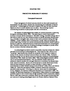
A major approach to the early validation of user requirements is based on exploiting the executability of formal specification languages. A conceptual model with executable properties can be interpreted as or automatically transformed to an executable prototype that can be evaluated to detect potential misconceptions expressed in the model. This process is usually called animation [HJS93, MJHB98]. Animation combines the advantages of formal specifications (e. g. unambiguity and analysability) and rapid systems prototyping (e. g. risk management and early user involvement). This is an attractive idea because the specification of a software system has to be produced, and no extra effort for prototype construction would therefore be needed. This is in contrast to other techniques, such as those using very highlevel languages where, after the prototype has been built and agreed with the users, the specification has to be constructed anew. The fact that the prototype is directly derived from the specification assures the consistency between the specification and the observed behaviour of the prototype. Animation can be embedded in various software development paradigms. Especially attractive are the combinations with protoyping, and with the operational and transformational approaches [Agr86]. As indicated in Fig. 2.1, the software development model followed by animating formal specifications starts with a requirements analysis. Afterwards an iterative requirements definition process is carried out which consists of the formal specification of requirements, the construction of the animation and the validation and elicitation of new requirements by executing the animation. Once the formal requirements specification is considered satisfactory, the realisation process starts. This process can either consist of conventional design and implementation phases, or it can be based on transformational implementation, i. e. the iterative application of transformations on a formal specification, which leads to the final product. The latter is usually considered in the literature as transformational programming [Zav84, PS83]. The goal of transformational programming is to transform a specification automatically into an executable software system that is certain to satisfy the initial specification and in which validation and maintenance are done at the specification level [Bal85].
20
Chapter 2. Conceptual Modelling and Validation Support Perceived Need
Requirements Capture
Execute Animation
Requirements
Build Animation
Specification
Other Development Phases
Figure 2.1: The Animation Process
The possibility of executing a specification depends on the degree of executability of the specification language. There is no consensus whether a specification should be executable or not. On the one hand, specifications should be declarative, i. e. they should describe what should be done and not how to do it. Hayes and Jones [HJ89] argue that executable specifications lack the expressibility of their non-executable counterparts, and that the demand of executability in the specification could influence implementation decisions. On the other hand, executability would be enormously profitable in order to be able to construct powerful validation tools. As argued by Fuchs [Fuc92], executable specifications allows us to obtain executable components at a very early stage, thereby allowing the earlier detection and correction of problems and the clarification of requirements that are unclear. There are several ways of animating a specification [Har92]. The specification can be animated in an interactive fashion allowing an explorative validation of the user requirements. Users can emulate the system’s environment by generating events. The animator, in turn, responds by transforming the system into the new resulting status. If the model is represented graphically, the change in status could be reflected visually, for instance, by changes in colour or emphasis in the diagrams [KK88, LL93]. Another possibility is
2.4. Validation through Animation
21
to execute the specification in a batch fashion. In this case, the sequence of events are read from a file. This allows outputs from scenario design editors [KSTM98] or specification-based test case generators [Pos96] to be used as inputs of the animator. Analogous to debugging tools of conventional programs, it is also possible to incorporate breakpoints, causing the execution to suspend and the animator to take certain actions when particular situations come up [Muk95]. For non-executable parts of the specification, it is sometimes possible to refine them using executable constructs of the specification language [Muk95, HJS93]. If such transformations are not possible, for instance, if the specification is non-deterministic or undetermined, the animator could warn or ask users to make a decision whenever they try to execute such expressions [Hey97]. Symbolic execution can also be used for animation purposes to specify symbolic values when the inputs, outputs or algorithms are not determined, or at least not uniquely [JJLM91]. An animation session would consist in identifying first a set of scenarios, where a scenario is a sequence of events which may occur in the domain of the system. This sequence of events is then tested against the specification to see whether the specification meets the intended user requirements involved in the scenario [Lan95]. Scenarios may represent both desired behaviour which the specification should allow, and undesired behaviour, which it should forbid. An animation session should be carried out by specifiers together with end users in order to observe and discuss whether the specification adequately describes the requirements that the future software system must fulfil. Users should bear in mind that the interface of the animation tool does not represent the eventual user interface of the system being developed. Since an exhaustive animation, i. e. testing the specification in all possible scenarios, is not practicable, a representative set of scenarios must be chosen. If requirements have been elicited using scenario-based techniques, scenarios obtained in the elicitation phase are the most appropriate to validate the specification [HD98, S´an00]. Another possibility consists in the use of automatic specification-based software testing techniques for obtaining test suites directly from the specification [Pos96]. The test suites which are used to test the specification can be reused later when testing the implementation. This helps to ensure a correct transformation from the specification into an implementation. Once the specification has been animated and observed that its behaviour meets the user requirements in a set of scenarios, we would like to affirm that such specification is correct with respect to the requirements. Unfortunately, a correct behaviour of the specification on a finite number of
22
Chapter 2. Conceptual Modelling and Validation Support
cases does not guarantee correctness. Thus, as Dijkstra said in relation to program testing [DDH72] , we can say that animation can be used to show the presence of bugs, but never to show their absence. Another issue is how to check whether the animation tool or prototype conforms to the dynamic semantics of the specification language. Several ways of doing this are discussed in [LP92]. As the compliance of compilers for programming languages is traditionally checked, one way is the use of test suites. The strategy consists in providing a significant number of tests, which the tool must execute in the way described by the semantics of the language. Of course, the tests can only give some degree of confidence that the prototyping tool is implemented correctly. Because of the formality of the specification language, it is possible in theory to carry out formal proofs showing that the animation tool complies with the semantics of the language. Unfortunately, since such formal definitions can be very complex and large, it will in most cases not be worth the investment, even when proof assistants are available. A more pragmatic way of checking compliance consists in showing that there is a systematic translation from the formal specification language to the animation tool. Of course, this way cannot ensure compliance but it can be made plausible. Although as yet no practical way exists to ensure or check compliance, if a specification language has formal semantics then it is potentially easier to check compliance than when no formal definition is given.
2.5
Description of the Work
This section describes and situates the work developed in this thesis in the context of the topics presented previously. As mentioned in the previous chapter, the aim of this thesis is the study and development of software tools that assist developers and users in the modelling and validation of conceptual models specified in Troll. Troll is a specification language with the following characteristics: • It is a formal language, i. e. its syntax and semantics are formally defined. The syntax is given in a EBNF form. Semantics are given to Troll specifications using different techniques: the static structure of the system is semantically described with algebraic methods, statements over states are expressed with a logic calculus, and the dynamic
2.5. Description of the Work
23
structure of the system, i. e. the systems evolution, is reflected via a temporal logic which is interpreted in terms of event structures. • It is object-oriented. Troll models a system as a community of independent objects that communicate with each other by a synchronous action calling mechanism. Objects are encapsulated units of structure and behaviour and are described in terms of object classes. Troll supports structuring concepts that are typical in object-orientation such as inheritance and composition. • Troll may easily be combined with graphical semiformal techniques such as UML. A graphical notation, called OmTroll and based on OMT, has been specifically developed for Troll. OmTroll consists of different diagrams that allows developers to give a first overview of the object system. A frame of a Troll specification can be derived from the OmTroll diagrams. This has to be refined to a complete system specification. Tools developed for Troll in the context of this thesis can be classified in two groups depending on the activities they support: • Modelling Support: They consist of graphical and text editors, a crossreference generator and a syntax and static semantics checker. An automatic translation between both graphical and text notations is provided by the editors. Specifications that are syntactically correct according to the EBNF rules do not necessarily obey the typing and scoping rules given by the static semantics of the language. We have analysed these rules and implemented a static semantics checker of Troll specifications. • Validation Support: For the validation of Troll specifications against user requirements, an animator has been constructed. This tool allows developers and users to observe, experiment and test interactively the dynamic properties of the specification through its execution in different scenarios. The modelling and validation of a specification are an iterative process. Validation can start as soon as a first version of the specification has been modelled. The only requirement is that the syntax and static semantics of
24
Chapter 2. Conceptual Modelling and Validation Support
the specification have been correctly analysed by the checker. Once the specification has been validated, it is modified in the editors accordingly. The specification can also be validated in several parts, obtaining for each part an executable prototype. The animator features are summarised as follows: • The animator has a graphical user-friendly interface in order to encourage the participation of end users in the validation process. • Users can explore the current state of the objects in the system and navigate through their components and specialisation aspects. • Users can simulate the occurrence of events in the system by selecting actions in the objects to be executed. • The execution trace, e. g. changes on attributes, interactions, etc., is shown on a console window. • If the state transition cannot be carried out, e. g. an action precondition is not fulfilled or an integrity constraint would be violated in the next state, explanatory messages are reported to the users. • Although the animator is used mainly for requirements validation, it also detects errors in the specification that cannot be statically checked, such as assignments of different values to the same attribute during a state transition. • Objects are persistent, i. e. they have a lifespan that is not limited to single executions of the animator. This allows users to interrupt anytime an animation session and with the same objects’ states to continue it later. • The animator supports the validation of large complex specifications by allowing data persistence and the use of complex data types such as records and lists, and in-the-large structuring mechanisms such as inheritance and composition. Objects created during the animation are stored in a relational database. We analyse how Troll objects can be mapped in relational tables and implement a database schema generator for Troll specifications. To execute the specification, we analyse the operational meaning of state transitions in Troll and determine an execution model using a sequential
2.6. Related Work
25
programming language. As we will discuss in the next chapters, Troll objects communicate with each other through a synchronous transitive action calling mechanism which entails the synchronisation between the life cyles of the participating objects. Aspects to take into account when executing the action chain established by the calling relation are parallel execution, conflicts in the assignment to attributes and variables, consistency, termination and atomicity. Since the operational properties of Troll partly coincide with the capabilities of object-oriented programming languages, we transform the specification into C++ code to obtain an executable prototype. We develop mapping rules from Troll into C++ and implement a Troll-C++ code generator. The code is generated to support the early validation of system requirements and is of a throw-away quality. Nevertheless, some techniques used for the automatic translation of the specification into executable prototypes can be adopted for the design and implementation of the final application. Tools are realised as stand-alone applications and integrated in a workbench environment. The syntax graph generated by the checker is stored in a file which is directly used by other tools through a common interface. So the tools do not need to parse the specification again whenever they are called. A common graphical front-end is provided by a specification projects manager tool from which the tools can be invoked and used together. So it is easy to modify the tools contained in the workbench or incorporate new ones. The goal of this work is the study and prototypical implementation of a software development environment to support the modelling and validation through animation of Troll models. Typical aspects of commercial CASE tools like multiuser support, versioning of specification documents, distributed execution and control integration by inter-tool communication are outside the scope of this thesis.
2.6
Related Work
Tool support has been an important issue from the very beginning of the development of Troll. For the first version of Troll [JSHS91, JSHS96], a syntax and static semantics checker was implemented in [Ste92, St¨o93]. First ideas about the early validation of Troll specifications through animation were sketched in [HJSE92, HJS93]. There, the authors propose the
26
Chapter 2. Conceptual Modelling and Validation Support
transformation of Troll specifications into a kernel language that can be executed in a suitable distributed runtime environment. Previous Troll versions to the current one included language constructs not directly or very difficult to implement such as the use of temporal logic formulae in the definition of action preconditions and integrity constraints. So they propose the translation of the specifications into an operational subset of the language. The idea was to translate the Troll kernel language into Sather [Omo91], a language based on Eiffel [Mey92], and build a runtime system handling the distributed management of state information on different database systems, the automatic routing of event callings, and the necessary transaction protocol. Interfaces to the UNIX file system and to the relational databases Ingres and Sybase, a graphical user interface and a minimal runtime system for test purposes were implemented in [Kus93]. Nevertheless, the development did not go on and no code generation was investigated. Parallel to the development of Troll, a reduced dialect called TROLL light [CGH92] was also developed. An open software development environment for the validation and verification of TROLL light specifications was presented in [VHG+ 93, GCD+ 95a, GCD+ 95b]. To verify properties of the specification, a verification calculus [Con94] was developed and implemented using a generic theorem prover. For validation purposes, an animator with basic functionalities was developed [HG94, Her95]. For the animation, specifications were first introduced into a template dictionary, which was implemented using the OODBMS ObjectStore [LLOW91]. The execution of events was carried out by an interpreter consisting of an execution module which computed the successor states [Bri93] and a term evaluator which evaluated terms and formulas [Ale93]. The object states were also stored in the database. Besides the animator did not show the execution trace, so it was very difficult to observe the behaviour of the specification, the language concepts supported by TROLL light were restricted with respect to the version of Troll dealt with in this thesis. In TROLL light, inheritance was not supported, action preconditions could not be expressed independently of a concrete process specification, only one action in an object could happen in a state transition, and the nonexistence of an explicit specification of input and output parameters in the object actions probably indicated that information flow via action parameters was only possible in one direction4. More recently, the 4
See Chap. 8 of [Har97a] for a detailed description of differences between Troll v. 3.0 and TROLL Light as well as previous Troll versions.
2.6. Related Work
27
development of a web-based animator for TROLL light with similar functionalities to the previous one has been reported in [RG97a, RG97b]. For the second version of Troll [HSJ+ 94, HKSH94], work towards the development of a software development environment, called TBench, was reported in [KHHS95a, KHHS95b]. The TBench project aimed at developing a distributed integrated software development environment based on the ECMA reference model [BEM92] for the specification and animation of Troll models. Tools developed within this project were a graphical editor [Alm94], a syntax-directed editor [Emb94, Mer94] and a tool for the integration between the tools and shared access to the repository [Kle94, BP94]. Although aspects concerning the executability of Troll v. 2.0 were investigated in [HS93, Har95] among others, no animator was developed. Based on the work reported above, we can state that the software development environment developed in this thesis represents the most complete environment, supporting graphical and textual modelling, syntax and static semantics checking and full generation of code for animation, developed for Troll and, hence, it represents a key improvement to support and extend the use of the language. Regarding other approaches with animation support, OASIS [LRSP98] is the most closely related to ours. Like Troll, OASIS is a formal objectoriented language for the specification of information systems. In the OASIS approach, specifications are also modelled using graphical notations, like OOMETHOD [PIP+ 97] or UML [BRJ98], which are then translated to textual OASIS specifications. Semantics for OASIS specifications are given by a set of logic formulae expressed in an extension of dynamic logic which is interpreted over Kripke structures. In the last years, special emphasis has been put on the animation of OASIS specifications in concurrent environments [LSR99]. An animation environment based on concurrent logic programming is presented in [LSR97, Let99] among others. In this environment, specifications are first modelled in a graphical editor and stored in a repository. Specifications are then translated into KL1 concurrent logic programs which are compiled in order to obtain an executable prototype. A graphical user interface allows users to simulate events, that can also be read from a file, and observe the actions occurred in the objects and the reached states. Although this animation environment and the one developed in this thesis share the same aims, there are important differences between the followed approaches. Besides the execution model followed in the OASIS animator is conceived for concurrent environments, in which each object has its own execution thread, and ours for sequential ones, a main difference between both approaches lies on the com-
28
Chapter 2. Conceptual Modelling and Validation Support
munication mechanism. In the OASIS animator, objects communicate with each other asynchronously while in the Troll animator, they communicate synchronously, i. e. communication entails a synchronisation between the life cycles of the participating objects. Unlike the Troll animator, the OASIS animator does not support inheritance, aggregation or integrity constraints, although it is planned to support them and also synchronous communication in future versions. Another animation environment for OASIS specifications based on Petri nets has been developed and reported in [SLR97, S´an00] among others. In this environment, OASIS specifications are first translated into logic dynamic formulae which in turn are translated into object oriented Petri nets (OOPNs). The generated OOPNs can be directly animated using a Petri nets animator tool. The execution traces obtained by the animation are then transformed into a legible fashion expressed in form of sequence diagrams. In this approach, the validation process takes place after the animation by analysing and contrasting the obtained sequence diagrams against scenarios developed during the requirements elicitation phase. In contrast, our validation approach is based on an interactive animation, in which users and developers simulate events and observe the system dynamics and object states during the animation session. Parallel to the development of these animators, another research direction within OASIS has been the development of a CASE environment supporting OO-METHOD, a methodology based on OASIS [PIP+ 97, PPIG98, PCR99]. The OO-METHOD CASE allows developers to specify graphically the system and, using OASIS as intermediate language, generates automatically code in several programming languages. Unlike in the Troll animator, the code generation in the OO-METHOD CASE is not oriented to validation purposes but rather to obtain the final application. Another language with animation support is ALBERT II [DB95, DB97]. ALBERT II is a formal requirements specification language designed to specify the requirements of distributed real-time systems. An ALBERT II specification consists of agents (active objects) which can perform or suffer actions that may change their states (denoting either physical or informational characteristics), and whose admissible behaviours are restricted by means of constraints. The semantics of an ALBERT II specification are given in a realtime temporal logic called ALBERTKERNEL . Work towards the animation of ALBERT II specifications has been reported in [Hey97, HD98] and elsewhere. Specifications used in the animator are edited in a graphical environment with syntax and type checking facilities. The animator allows step-by-step testing
2.6. Related Work
29
of scenarios against the specification using an interpretation algorithm. Unlike the Troll animator, the main challenges of the ALBERT II animator are to provide a distributed tool which allows stakeholders to cooperatively animate a specification and to deal with undeterminism. Troll has its roots in the specification language OBLOG [SSE87]. While Troll aims have been focussed on the academic realm, special emphasis has been put on the development of OBLOG as a commercial product. The current version of the language combines a graphical notation, which is UML compliant, with a textual one. The textual notation is mainly used for the design details. A commercial CASE environment has been developed supporting the edition, validation, reverse engineering and automatic generation of application code and documentation of OBLOG specifications5 . A main feature of the OBLOG CASE environment is the use of customisable transformation rules in the generation of code allowing the support for multiple target languages and architectures. For validation purposes and making use of the Java generation rules, a Java prototype can be automatically generated from the specification. An animator allows users to interact with the prototype visualising the results of the animation in a form of interaction diagrams. Although OBLOG was originally developed with a sound theoretical basis, it is unclear, regarding the information obtained from its web page, whether the commercial version still maintains the theoretical backgrounds. Nowadays there exists a great variety of formal specification languages supported by software tools6 . The spectrum of these tools ranges from editors, syntax and type checkers to verification and validation tools. Regarding validation support, the model-based languages Z [Spi92] and VDM [Jon90] are the main languages for which animation tools have been developed (see, for instance, [MJHB98, O’N92, ELL94]). A general problem of current animation environments is that due to the abstract notations of the specification languages and the complex way their execution behaviour is usually presented to users, they are more oriented to developer validation than user validation ¨ [Ozc98]. A large number of commercial CASE tools supporting object oriented analysis and design techniques is currently available7. Although these tools 5
The first commercial version of the OBLOG toolset was released in 1999. The OBLOG web site is located at http://www.oblog.com. 6 For an overview of tool support for formal methods, we refer the reader to the web page http://www.comlab.ox.ac.uk/archive/formal-methods.html 7 For a good overview of current OOAD CASE tools we suggest the reader to consult
30
Chapter 2. Conceptual Modelling and Validation Support
include powerful graphical editors, most of them supporting UML notations, and automatic code generation, which ranges from generation of headers and program skeletons to complete application code, only a few of them provide specific support to requirements validation. BridgePoint8 provides a “Model Verifier” module which allows Shlaer-Mellor models to be executed for debugging prior to code generation. Some CASE tools such as ObjecTime9, Rhapsody10 and BetterState11 that model behaviour with state machines allow the animation of these models by adding code, e. g. in C++ or in a proprietary language, to represent actions that occur on the state transitions. In Rhapsody and ObjecTime, models are validated by contrasting the execution traces against scenarios expressed as sequence diagrams (in ObjecTime, this can be done automatically).
2.7
Summary
A main activity in the conceptual modelling process is the validation of the specification against the informal user requirements. Validation requires the participation of users because they provided the original requirements. A limitation of formal specifications is that they cannot be readily understood by users unless they have been specially trained. A technique for making easier the user participation in the validation process consists in exploiting the executability of the specifications. By animating the specification users can observe the dynamic behaviour of the specification in different scenarios to see if it meets their real needs. This thesis concerns with the study and development of software tools that assist developers and users in the modelling and validation through animation of conceptual models specified with Troll. The tools consist of graphical and text editors, a cross-reference generator, a syntax and static semantics checker, and an animator. Objects created during the animation are stored in a relational database. To this end, we analyse how the static structure of Troll objects can be mapped into relational tables. In order to execute the specification, we analyse the operational meaning of state transitions in Troll, give an execution model the web page http://www.cetus-links.de/oo ooa ood tools.html 8 http://www.projtech.com 9 http://www.objectime.com 10 http://www.ilogix.com 11 http://www.isi.com
2.7. Summary
31
and develop mapping rules from Troll into C++. The executable prototypes are generated automatically. In the animator, users can observe the current state of the objects, navigate through their relationships, simulate the occurrence of events and observe the execution traces. With the work developed in this thesis, we show that far from being a handicap, formal specifications represent a key improvement in the validation process by allowing the construction of powerful validation tools such as specification animators.
33
Chapter 3 The Troll Approach to Conceptual Modelling A formalism or methodology for specifying information systems may be described as the symbiosis of three concepts: a language, a method for using the language and a set of tools to support developers in the modelling process. In this chapter, we introduce the textual object-oriented specification language Troll together with its graphical part OmTroll and illustrate the language concepts by example. After a brief introduction in Sect. 3.1., we present the modelling with OmTroll and Troll in Sect. 3.2 and Sect. 3.3 respectively. The formal semantics underlying the Troll language are briefly described in Sect. 3.4.
3.1
Introduction
Troll (Textual Representation of an Object Logic Language) is a formal object-oriented specification language for specifying information systems at a high level of abstraction. Troll belongs to the OBLOG (OBject LOGic) family of languages. OBLOG was first presented in the publication [SSE87] as a language for specifying software systems as a society of interacting objects. The semantic foundations of OBLOG are based on the concept of abstract object types, an extension of abstract data types to cover objects and object systems. Since 1987, OBLOG and its supporting CASE environment have been further developed [CSS89, Esp93] becoming a commercial product. At the university and based on OBLOG there are two
34
Chapter 3. The Troll Approach to Conceptual Modelling
related developments: Troll and Gnome [SR94]. Troll is currently in its third version [DH97, Har97a, GKK+ 98]. Previous versions are Troll v. 0.01 [JSHS91, JSHS96], TROLL light [GCD+ 95b] and Troll v. 2.0 [HSJ+ 94, HKSH94]. In contrast to older versions, Troll version 3.0 is devoted to modelling distribution issues and has also been designed with the aim of executability. The design of Troll v. 3.0 has been significantly influenced by the experiences gained in an industrial project in which Troll has been used as the modelling language. The project started in 1994 in cooperation with PTB (Physikalisch-Technische Bundesanstalt1 ). It aims at developing an information system which supports the testing and certifying of explosion proof electrical equipment. The system is called CATC (Computer Aided Testing and Certifying) and includes different subsystems based on the certifying process [HDK+ 97, KG98]. Troll has also a graphical part called OmTroll. The graphical notation serves for giving a first overview of the system and as a means of communication between users and developers. The textual notation incorporates all language concepts, whereas the graphical notation covers only part of the concepts. From OmTroll a frame of a textual Troll specification can be derived. The textual specification has to be refined to a complete system specification. Fig. 3.1 depicts the Troll design process. A method
Analysis
OMTROLL TROLL Design
Implementation
Use and Maintenance
Figure 3.1: The (Om)Troll Design Process 1
German Federal Institute of Weights and Measures.
3.1. Introduction
35
for using the language concepts is given in [Kow96, DH97]. The method consists of a series of steps and rules that guide developers during the modelling process. In the next sections, we present OmTroll and Troll by modelling a simplified extract from the CATC system and according to these steps. Next, we describe briefly the CATC system. Example 3.1.1 (CATC System) The CATC project aims at designing an information system for supporting the various activities of group 3.4 within PTB. The group is concerned with testing and certifying electrical equipment, e. g. motors, switches, heaters, which are to be used in explosionhazardous areas. The certifying process for electrical equipments is composed of the following parts: • Administration management includes the preliminary screening of documents concerned with the company producing or providing the electrical equipment. Such documents contain, for instance, the name and address of the company and the technical description of the equipment. • Design approval includes the assessment of design papers for the equipment based on descriptions and its accordance with the European standards. Here the staff creates a check list including the necessary experiments that have to be done by the operators. • Experimental tests are performed by the operators in the test lab and store all relevant data. There are different tests depending on the kind of electrical equipment (for example, temperature tests for heaters and pressure test for motors). The tests are done on samples sent by the company. Once the tests have been performed, the staff reads the results and decides whether more tests are necessary. Otherwise, the certification may be issued. The example used for illustrating the Troll concepts along this thesis concentrates on the experimental part of the system. The testing process is a cooperation between staff and operators. Both of them have to access to the test results. The operators produce and store the test results while the staff reads and interprets them. Due to European standards, every application should be tested by more than one experiment to avoid any mistake. While the experiments for one application are running, the staff may set up a next experiment. �
36
Chapter 3. The Troll Approach to Conceptual Modelling
3.2
OmTroll
The use of graphical notations in the specification of software systems such as entity-relationship (ER) models and data flow diagrams (DFD’s) has always found a widespread acceptance. Especially in the last years, a great variety of graphical object-oriented analysis and design techniques such as UML [BRJ98] have aroused and become very popular. The reason for this success is that graphical notations are usually more intuitive and easier to understand than textual notations. The Troll modelling process combines the simple expressiveness of these popular notations with the formal nature of Troll taking the advantages from both of them. OmTroll [WJH+ 93, JWH+ 94, DH97] consists of different diagrams for modelling a system. The idea is to use OmTroll at the very beginning of the modelling process in order to obtain an abstract outline of the system. The information which is represented in the OmTroll diagrams becomes the underlying information used for the Troll specification. OmTroll is based on the popular Object Modelling Technique (OMT) method developed by Jim Rumbaugh [RBP+ 91]2. The OmTroll graphical specification allows the initial design to be realised through the use of several system views: community model, data type model, object model, dynamic model and communication model. Each view is associated with a specific diagram: • The community diagram gives an overview of the object classes and their respective relationships to each other. • The data type diagram represents user defined data types which are defined over standard data types. • The object class declaration diagram allows the developer to describe each object class in further detail. That is, the developer can define attributes and operations relevant to each class. • The behaviour diagram defines the life cycle of the objects. The main aim of the behaviour diagram is to determine preconditions of actions and dependencies between action executions. 2
Recently OMT has been combined with other popular object-oriented design techniques becoming UML (Unified Modelling Language)
3.2. OmTroll
37
• The communication diagram establishes the communication structure between the objects of the system. This diagram is not present in OMT and can be compared with Fusion diagrams [CAB+ 94]. In the following, we describe each of these diagrams by example. Appendix A.1 describes the syntax of the OmTroll diagrams. A more detailed description of OmTroll can be found in [DH97]. Community Diagram The community diagram represents the structure of the objects in the system. An object system is defined as a community of concurrent interacting objects. Objects are classified into object classes. An object class is a generic template for describing objects with similar properties and common behaviour. Object classes may be aggregated or specialised. They may have other object classes as components (part-of relationship) as well as specialisations (is-a relationship). A specialisation (subclass) inherits and extends the properties of a base class (superclass). The next example illustrates the community diagram of the CATC system. Example 3.2.1 (Community Diagram of CATC) The community diagram is depicted in Fig. 3.2. The system has two kind of objects: IG34 and Users IG34 Group
Applications(appNr:nat) Application Experiments(expNr:nat) Experiment
Staff
Companies(compId:nat) Company Users(userId:nat) User
Operator
Figure 3.2: OmTroll Community Diagram which are described by the classes Group and User respectively. IG34 represents the information managed in the certifying process by group 3.4 of PTB.
38
Chapter 3. The Troll Approach to Conceptual Modelling
It is composed of Applications and Companies. Components are represented by a diamond and the filled dots at the top of the object classes denote multiple components. An Application may have several Experiments as components. Users may be specialised in Staff and Operator. Specialisation is denoted by a triangle. � Data Type Diagram User-defined data types are defined in the data type diagram. Apart from predefined data types, Troll allows the use of constructors such as list and record for building new data types. Data type definitions will be presented in more detail in the next section. Example 3.2.2 (Data Type Diagram of CATC) Fig. 3.3 shows some data type definitions of the CATC system. Experiments may be performed in different labours. This is depicted by the enumeration type labours. The type of users is represented by users type. The setup for an experiment (msset) is defined as a record consisting of a pressure value which will be put in the device during a predefined time. The experiment results (msresults) are defined by a list of real numbers that represent the final pressures in the device. Finally, a company address is represented by a record containing the street, number and city where the company is located. � labours l3_41 l3_42 l3_43
msset record
press time
msresults list
real real
real
users_type admin staff operator
address_type record
street nr city
Figure 3.3: OmTroll Data Type Diagram
string nat string
3.2. OmTroll
39
Object Class Declaration Diagram Classes are further specified in object class declaration diagrams. Attributes and actions relevant to each class are declared here. The declaration of an attribute is given by its type and additional properties. Attributes may be initialised (\i), constant (\c), hidden (\h), optional (\o) or derived (\d). Actions may have input and output parameters, so objects can exchange information with each other. Apart from update actions, there are birth and death actions which create and destroy objects respectively. Birth actions are marked with a “*” and death actions with a “+”. Actions may also be hidden. Object declaration diagrams and the community diagram define the structural part of the system and are usually represented together. Example 3.2.3 (Object Class Declaration Diagrams of CATC) The object class declaration diagrams of Application and Experiment are depicted in Fig. 3.4. Attributes of the class Application are company, labour, app date and nextExpNr. company is an object valued attribute that makes Applications(appNr:nat) Application company : |Company| \c labour : labours max_pressure : real \c nextExpNr : nat \i \h *createAppl(comp:|Company|, max_press:real, lab:labours) newExperiment(nam:string, st:msset, !expNr:nat) +deleteAppl() Experiments(expNr:nat) Experiment name : string \c setup : msset \c results : list(msresults) \i assessments : list(string) \i *createExp(nam:string, st:msset) giveSetup(!st:msset) storeResults(res:msresults) giveResults(!res:msresults) storeAssessment(assmt:list(string)) +deleteExp()
Figure 3.4: OmTroll Object Class Declaration Diagram
40
Chapter 3. The Troll Approach to Conceptual Modelling
reference to an object of class Company. company is a constant attribute, i. e. its value is set at the beginning and never changes. labour denotes the labour to which the application is assigned. max pressure indicates the maximum pressure which can be set up in the experiments for the application. nextExpNr represents the identity number of the next experiment to be performed to the application. It is initialised and hidden, i. e. it is only visible inside the class Application. The birth action of an Application is createAppl and its input parameters represent values for the class attributes which are not initialised. The action newExperiment represents the creation of a new experiment for the application. It has as input parameters the name and setup for the experiment to be created and as output parameter the identity number of the experiment. Output parameters are denoted by prefixing a “!” before its name. The class Experiment has as attributes the name, the setup, the results and the list of assessments of the experiment. The actions of Experiment are explained below in the description of the behaviour diagram. � Object Behaviour Diagram Object behaviour diagrams are state transition diagrams representing the local behaviour over time of the objects. A state diagram is a directed graph whose nodes represent states and whose arcs represent transitions between states. Arcs are labelled by the actions which cause the transition and may also contain enabling preconditions. Troll does not explicitly support the definition of states. So states in behaviour diagrams are used for auxiliary purposes. As a consequence of it and unlike the rest of OmTroll diagrams, object behaviour diagrams cannot be directly translated into Troll. This issue will be discussed later in the presentation of the OmTroll editor in Sect. 7.2.2. Example 3.2.4 (Object Behaviour Diagrams of CATC) Fig. 3.5 shows the object behaviour diagrams corresponding to an experiment and an operator. Analogous to birth and death actions, there are initial and final states. A dot represents an initial state, a circled dot depicts a final state. The life cycle of an experiment starts with its creation (createExp). Setup information is then requested by the operator in charge in order to set up and start the experiment (giveSetup). Next, the experiment results are stored (storeResults) and returned by request (giveResults). Once the results
3.2. OmTroll
41
are given, assessments about the results may be stored (storeAssessment). Finally, an experiment is deleted through its death action (delExp) going to its final state. Operators are created in the system by the execution of the birth action (login). They ask then the setup information for an experiment (askSetup), perform the experiment (startExperiment) and store the results (giveResults). Once the results are stored, operators may either request the setup information for a new experiment (askSetup) or exit the system (logout). � Experiment
createExp
created
Operator
login
giveSetup
idle
askSetup
setup asked
startExperiment setup given
deleteExp storeResults asess. stored
storeAssesment
exp. started
askSetup
storeAssesment results stored
results given
giveResults
giveResults
logout results given
Figure 3.5: OmTroll Object Behaviour Diagram
Communication Diagram Interactions among objects are depicted in communication diagrams. Objects interact with each other through action calling. Communication diagrams show for each action its calling relations. Action calling may be either local, i. e. inside a complex object, or global, i. e. among two concurrent objects. The latter means a synchronisation relation in the life cycle of the objects. In Troll, action calling is directed and synchronous. Example 3.2.5 (Communication Diagram of CATC) The communication diagram depicted in Fig. 3.6 shows the communication among objects participating in the testing process. The creation of an experiment entails the
42
Chapter 3. The Troll Approach to Conceptual Modelling
synchronous execution of three actions: createExperiment in Staff which calls the action newExperiment in the Application with identity AppNr which in turn calls the birth action of the component Experiment with identity expNr. The Operator has to know under which pressure and time the test has to be done. To this end, (s)he asks for the setup values (askSetup) and gets the answer from the action giveSetup in Experiment. After performing the test, (s)he stores the results in Experiment. On the other hand, the Staff asks for the results, checks them and store his/her assessments.
Staff createExperiment(appNr, nam, st, expNr) askResults(appNr, expNr, res) checkResults(appNr, expNr, res) giveAssessment(appNr, expNr, assmt)
IG34.Applications(appNr) Application *createAppl(comp, max_press, lab) newExperiment(nam, st, expNr) +deleteAppl()
Experiments(expNr)
IG34.Applications(appNr).Experiments(expNr) Experiment *createExp(nam, st) giveSetup(st) Operator storeResults(res) askSetup(appNr, expNr, st) giveResults(res) startExperiment(appNr, expNr, st) storeAssessments(assmt) giveResults(appNr, expNr, res) deleteExp()
Figure 3.6: OmTroll Communication Diagram
�
3.3
Troll
As mentioned in Sect. 3.1, a frame of a Troll specification can be derived from the OmTroll diagrams. The textual specification has to be refined to a complete system specification. Fig. 3.7 shows the structure of a Troll specification. It consists of four parts: data type definitions, object class specifications, object declarations and a global behaviour specification.
3.3. Troll
43
user defined data types
data type = class declarations
object class aspect of if . . . components () : [hidden] attributes : [constant, optional, initialized, derived, hidden] actions (p1 :t1, . . . , pn :tn ) [hidden] behavior (p1 , . . . , pn ) onlyif () var :, . . . do assignments, callings, conditionals, iterations od constraints [initially] ,. . . end object declarations
objects () : global interaction definitions
behavior (p1 , . . . , pn ) do ... od Figure 3.7: Structure of a Troll specification
44
Chapter 3. The Troll Approach to Conceptual Modelling • Data Type Definitions: This part includes the definition of user data types. • Object Class Specifications: They define prototypical object descriptions. An object class consists of a signature and a behaviour definition. Attributes and actions are declared in the signature part. The behaviour of an object is defined by the description of rules for its actions and the declaration of integrity constraints. Preconditions may also be declared to restrict the occurrence of actions. Possible action rules are assignments, action callings, conditionals and iterations. Object classes may be complex. They may have other object classes as components (part-of relationship) as well as specialisations (is-a relationship). • Object Declarations: Objects are declared over object classes. These declarations describe the set of concurrent objects in the system. • Global Behaviour Specification: This part describes the interactions between concurrent objects in the system. Objects may communicate with each other by action calling where data flow is modelled via input/output parameters. All actions involved in an interaction are understood to take place simultaneously.
The Troll syntax can be found in Appendix A.2. For a more complete description of Troll see [DH97, Har97a]. In what follows, we describe each of these parts in further detail. To illustrate the concepts, we use the example of the CATC system. The complete Troll specification of the example can be found in Appendix B. Data Type Definitions Troll has a range of predefined data types: nat, int, real, money, bool, string, char and date. In addition, Troll allows the use of data type constructors. Users can apply these constructors to predefined or user-defined data types in order to construct complex data types. The constructors are: list(t), set(t), bag(t), record(id1:t1 ,. . . ,idn :tn ), map(id:t1,t2 ), enum(id1 ,. . . ,idn )
3.3. Troll
45
Predefined generic operations for the type constructors such as concatenation, head, tail etc. of lists are also available. We illustrate the definition of data types by example. Example 3.3.1 (User-Defined Data Types) Data type definitions can directly be derived from OmTroll data type diagrams. In Fig. 3.3 we illustrated the OmTroll data type diagram representing the user-defined data types of the CATC system. The corresponding data type definitions in Troll are: labours users type msset msresults address type
= = = = =
enum(l3 41,l3 42,l3 43); enum(staff,operator); record(press:real,time:real); list(real); record(street:string,nr:nat,city:string); �
Besides predefined and complex data types, there are object-valued data types. Each object class specification defines implicitly an identification data type. Identification data types represent references to objects. They are denoted by the class names enclosed by vertical lines (||). For instance, in example 3.2.3 we defined in the class Application the attribute company as a reference to an object of class Company (|Company|). Object Class Specifications A class specification describes the local structure and behaviour of objects whose properties are similar. Classes are generic object templates. They are not containers of object instances. As we will see later, objects are declared and identified outside the classes. An object class specification is composed of two parts: a definition and an implementation part. The definition part consists of three parts (all optional): a signature declaration for attributes and actions, a component declaration and a specialisation declaration. On the other hand, the implementation part includes operation definitions for actions and constraints. The former describes what are the effects of the actions and under which preconditions they may occur. The latter can be used to formulate static integrity constraints for objects. Next, we describe briefly each of these parts.
46
Chapter 3. The Troll Approach to Conceptual Modelling
Signature Declaration An attribute declaration is given by its name, data type and special features. An attribute may be: • constant: The value of a constant attribute is set at the birth of the object and remains fixed throughout the object’s lifetime. • optional: The value of an optional attribute does not have to be fixed at the object’s creation and can be fixed later. • initialized: Initialised attributes have a fixed value at its object’s birth. This value is independent of any object generation. • derived: The value of derived attributes are determined by values of other attributes. • hidden: Hidden attributes are only visible in the classes in which they are declared. An action declaration is given by its name and parameters. In addition, an action may be declared hidden. A hidden action is only known in the class in which it is declared. Birth and death actions create and destroy objects respectively. The signature declaration can be derived from the object class declaration diagram. Additionally, initial values for initialised attributes and derivation rules for derived attributes must be specified. We illustrate the declaration of attributes and actions in example 3.3.2. Component Declaration In Troll, components are not shared by objects, i. e. a component exclusively belongs to an object. Components do not have an autonomous existence. They depend existentially on the composite object to which they belong. Components may be single or multiple. The latter are identified by a parameter. The signature of a composite class is extended by the signatures of its components. This means that visible attributes and actions of component classes are also visible in the composite class. Attributes may only be assigned in the class in which they are declared. So composite classes have only read-access to the attributes of their components. In order to restrict
3.3. Troll
47
the visibility of a component to the class in which it is declared, the component may be declared as hidden. The next example shows the signature and component declarations of a class. Example 3.3.2 (Signature and Component Declarations) Fig. 3.2.3 depicted the object class declaration diagram corresponding to an Application in the CATC system. The corresponding Troll specification is defined as follows: object class Application components Experiments(expNr:nat):Experiment; attributes company : |Company| constant; labour : labours; max pressure : real constant; nextExpNr : nat initialized 1, hidden; actions * createAppl(comp:|Company|, max press:real, lab:labours); newExperiment(nam:string,st:msset,! expNr:nat); + deleteAppl; ... end ; � Specialisation Declaration A class may be the specialisation of another class. A specialisation represents a particular aspect of a basis class. It adds new properties to the basis class. In Troll, specialisations are static. That is, objects are specialised at the moment they are created and cannot get new aspects or give up existing ones during their lifetime. Multiple inheritance is not allowed, i. e. a class may only be the specialisation of one basis class. However, specialisations of a basis class do not have to be disjoint, and hence an object may have several specialisation aspects. A specialisation declaration is given by the superclass name and a set of birth actions belonging to the superclass. If necessary, the set of birth actions may have formulas in order to restrict the specialisation conditions. The signature of the basis class is embedded in the specialisation classes. Thus attributes and actions of the basis class are visible in the specialisations. Furthermore, the behaviour of an action of
48
Chapter 3. The Troll Approach to Conceptual Modelling
the basis class may be extended in specialisations. Next, we illustrate the declaration of specialisation classes by example. Example 3.3.3 (Specialisation Declaration) As mentioned in example 3.2.1, users of the CATC system may be specialised in staff and operators. This is depicted as follows: object class User ... actions * login(name:string,dat:date,user t:user type); ... end ; object class Staff aspect of User if login(name,dat,user t) and user t=staff ... end ; object class Operator aspect of User if login(name,dat,user t) and user t=operator ... end ; An object of class User will also be of class Staff if it is created by the birth action login and the input parameter user t is set to staff. On the other hand, the object will be of class Operator if it is also created by the action login, but user t is set to operator. � Behaviour Specification The behaviour specification of an object class contains the definition of operations to be executed by the occurrence of actions and the definition of integrity constraints. Unlike other parts of a Troll specification, the behaviour part cannot completely be obtained from the OmTroll diagrams. Although local communication can be derived from the communication diagram, the rest of the behaviour specification has to be directly written in Troll. Nevertheless, object behaviour diagrams may help in this step. Preconditions can be defined in order to restrict the occurrence of actions. An action can only occur if its precondition is satisfied. In Troll, a state transition can only happen if all actions involved in the transition can occur, i. e.
3.3. Troll
49
all their preconditions are fulfilled. We will discuss Troll state transitions later in Sect. 6.1. Local variables may also be declared for each action. The effect of an action is defined by action rules. There are four kind of action rules: • valuation rules: Values can be assigned to attributes, output parameters and local variables. • calling rules: Actions may call other local actions. Local actions also include actions defined in component and basis classes. Communication between components can be specified in the composite. When an action is called, data terms with defined values have to be specified for each input parameter. For the output parameters, local variables may be defined. • iteration rules: Multicalls can be specified by iteration rules. A multicall is the simultaneous call of several actions usually belonging to component objects. • conditional rules: Different behaviour can be specified depending on a condition. The fulfilment of the condition may be determined by the current values of attributes and input parameters. Thus its satisfaction may be state-dependent. Since the signatures of components are embedded in the composite, the behaviour of component actions can also be defined in the complex class. Similarly, the behaviour of actions belonging to a superclass can be defined in its specialisations. In both cases, the behaviour rules of an action are never overridden but extended. We will come back to this later. Apart from defining operations for the actions, the behaviour of an object can be given by the definition of constraints. Integrity constraints restrict the possible values of attributes. They can be defined as initially meaning that the constraint has to be satisfied at least in the first state of the object’s life. In other case, constraints are defined as static, i. e. they have to be satisfied in every state. Constraints are defined using first order logic formulas that may be quantified over finite sets. The following example depicts the behaviour specification of a class. Example 3.3.4 (Behaviour Specification) The signature declaration of the class Application was presented in example 3.3.2. There, two actions were
50
Chapter 3. The Troll Approach to Conceptual Modelling
declared: the birth action createAppl and the action newExperiment. The local behaviour definition of these actions and the definition of constraints for the class attributes are defined as follows: object class Application ... behavior createAppl(comp,max press,lab) do company := comp, max pressure := max press, labour := lab od ; newExperiment(nam, st, expNr) onlyIf (st.press = n then b:=60 fi od ; ... end; objects objA : A;
Independently of the current state, the execution of objA.act1 does not present any conflict in the assignment to the attribute B. As can be observed, act2 only changes the value of B if a >= n, but act2 is only called by act1 if a < n. A syntax check as depicted above would however reject the specification. Note that if we change the conditional of act1 to a 9) V_dataTypeSpec_list (9, 1, no info) ... E_objectClassSpec_list (314, 8 -> 194) V_objectClassSpec_list (194, 1, no info) E_first (315, 194 -> 193) E_elem (317, 194 -> 193) V_objectClassSpec (193, 10, application.trl) E_class_id (308, 193 -> 67) V_class_id (67, 10, Application) ... E_objectDecl_list (514, 8 -> 320)
7.2. Tools Description
161
V_objectDecl_list (320, 1, no info) ... E_behaviorSpec_list (786, 8 -> 464) V_behaviorSpec_list (464, 1, no info) ...
The arguments in a vertex show its identification value, the line number in the text file in which the token appears and a value whose meaning depends on the vertex type. The arguments in an edge represent its identification value and the initial and terminal vertexes. The root vertex, V systemSpec, has four children vertexes containing the data type, object class, object and global behaviour definitions of the specification. The first element in the list of object class specifications is the class Application that is specified in the file application.trl, line number 10. The remaining Troll tools access the graph by a common interface. So changes in the graph structure do not require changes in these tools. The graph interface provides access functions at an abstract level. These functions return, for instance, the attributes for a given class or the operations defining the behaviour of a given action. The graph interface and its implementation are described in [Voe99].
7.2.5
trldoc - Troll Documentation Tool
trldoc reads the graph generated from the specification by trlcheck and generates HTML code. The generated code can be viewed in any HTML-browser supporting Java Scripts and frames. The code allows hypertext navigation through the specification and the introduction of informal comments to document the model. Additionally, trldoc allows to print the complete specification together with the informal comments in one document. trldoc can be considered as an unparser that adds the missing concrete syntax of the specification to the abstract syntax contained in the graph to obtain a structured representation of the original text specification. Fig. 7.9 shows a screenshot of Netscape browsing the HTML code generated from the CATC specification. The window’s layout consists of four frames. The left frame contains links to the main declaration parts of the specification: data types, object classes, objects, and system behaviour. Clicking on one of these links shows the corresponding declaration list on
162
Chapter 7. The Troll Workbench
Figure 7.9: trldoc – Hypertext Navigation through the Specification
the main frame at the right side of the window. Under object classes, a list of all classes defined in the object system is displayed together with the source file names and line numbers in which the classes are defined. If an object class is selected from this list, links to all the parts specified within the class (specialisations, components, attributes, actions, local behaviour definitions and constraints) are displayed. Following these links, the corresponding definitions are shown. Definitions provide further links to other parts of the specification (component classes, specialisations, data types, etc.). The Troll source code files may be displayed on the main frame by clicking on the corresponding links at the bottom of the left frame. Comments for the current displayed declaration are shown on the frame below the main frame. Pressing the buttons with the back/forward arrows on the bottom frame redisplay the documents that were loaded before/after the current one. The help button gives instructions on using trldoc. The Troll logo at the left side displays information about the Troll project. Informal comments
7.2. Tools Description
163
for each specification component can be introduced by pressing the “Edit comment” button. A textarea entry then appears at the comments frame. This is depicted in Fig. 7.10. Comments are directly edited in HTML. So
Figure 7.10: trldoc – Introduction of Informal Comments
it is possible to use different fonts and colours and to introduce not only text but also figures, etc. Below the textarea, there are buttons for saving the comment, restoring the original comment before the current changes or cancelling without saving. trldoc can be called with an option to generate a Postscript file containing the Troll specification together with the informal comments. To do this, trldoc uses the HTML-Postscript generator html2ps7. trldoc has been implemented in C++ and Perl. For implementation details, the reader is referred to [Ger00]. 7
html2ps is a free software tool. Information about this tool may be found at its home page http://www.tdb.uu.se/˜jan/html2ps.html.
164
7.2.6
Chapter 7. The Troll Workbench
trldbgen - Troll Database Generator
trldbgen reads the static structure of the specification contained in the syntax graph and generates a database schema. The database stores the object instances created during the animation. trldbgen has been implemented in C++ and uses Postgres as DBMS. In order to generate the database schema, trldbgen makes a connection to the Postgres backend server and sends then the corresponding SQL commands. As mentioned in the presentation of trlbench, this tool can also be called with an option that stores the generated SQL statements into a file to be processed later. The database generation is based on the transformation rules presented in Chapter 5. In the next, we show some of the SQL commands used in the database definition of the CATC system. The generation of surrogate keys (SOIDs) for the objects contained in the database is implemented using the sequence constructor provided by Postgres. A sequence number generator is created as follows: CREATE SEQUENCE OID_seq increment 1 start 1
After the sequence is created, the function nextval(OID seq) returns a new value from the sequence. During the animation, the persistence layer uses some special tables to find out the objects in the database. These tables are created as follows: CREATE TABLE hierarchy ( complex table text, child table text, type text NOT NULL, PRIMARY KEY (complex table, child table)) CREATE TABLE classes ( table name text, class name text NOT NULL, PRIMARY KEY (table name)) CREATE TABLE complex attributes ( complex table text, child table text, type text NOT NULL, PRIMARY KEY (complex table, child table))
The table hierarchy stores the hierarchy relationships between tables. The type of relationship is stored in the column type (either “component” or “specialisation”). For each table in the database storing Troll objects, the table classes stores the name of the corresponding Troll class. The table complex attributes stores the relationships between tables representing Troll objects and those representing complex attributes. The column type stores the constructor type of the attribute (list, set, etc.). These tables are
7.2. Tools Description
165
instantiated by the database generator during the creation of the respective tables. For example, let ig34 and applications 1 be the tables storing the objects IG34 and applications respectively, the following commands are generated: INSERT INTO classes VALUES (‘ ig34’, ‘Group’) INSERT INTO classes VALUES (‘ applications 1’, ‘Application’) INSERT INTO hierarchy VALUES (‘ ig34’, ‘ applications 1’, ‘comp’)
The table ig34 contains objects of class Group and the table applications 1 contains objects of class Application that are components of the objects contained in the table ig34. Postgres does not support the definition of foreign keys. So referential integrity constraints are implemented by triggers. For instance, the table applications 1 and the component relationship between applications and IG34 are defined as follows: CREATE TABLE applications 1 ( soid int DEFAULT nextval(’OID seq’), complex int NOT NULL, par int NOT NULL CHECK (par >= 0), PRIMARY KEY (soid), UNIQUE (complex,par)) CREATE FUNCTION check cascade applications 1 ig34 () RETURNS opaque AS ‘BEGIN DELETE FROM applications 1; WHERE OLD.soid = complex; RETURN OLD; END;’ LANGUAGE ‘plpgsql’; CREATE TRIGGER tg check cascade applications 1 ig34 BEFORE DELETE ON ig34 FOR EACH ROW EXECUTE PROCEDURE check cascade applications 1 ig34 ()
As defined in the transformation rule 5.2.2 on page 95, the table containing the component objects includes a column (complex) that refers to the primary key of the table containing the compound objects. The trigger defines that whenever an object of the compound table ( ig34) is deleted, then all its components are deleted from the component table ( applications 1). Note that since the SOID of an object never changes, referential integrity checks in update operations are not required. On the other hand, the referential integrity in insert operations in the component table is assured directly by the persistence layer. Once the table applications 1 has been created, the attributes of the class Application are mapped into columns of this table as follows:
166
Chapter 7. The Troll Workbench
ALTER TABLE applications 1 ADD ( labour text NOT NULL CHECK ( labour in "l3 41", "l3 42", "l3 43")) ALTER TABLE applications 1 ADD ( max pressure real NOT NULL) ALTER TABLE applications 1 ADD ( nextexpnr int NOT NULL CHECK ( nextExpNr >= 0)) ALTER TABLE applications 1 ADD ( company int NOT NULL) CREATE FUNCTION check ref applications 1 companies 1 () RETURNS opaque AS ‘DECLARE rec RECORD; BEGIN SELECT * INTO rec FROM applications 1 WHERE OLD.companies 1 soid = company; IF FOUND THEN RETURN NULL; ELSE RETURN OLD; END IF; END;’ LANGUAGE ‘plpgsql’; CREATE TRIGGER tg check ref applications 1 companies 1 BEFORE DELETE ON companies 1 FOR EACH ROW EXECUTE PROCEDURE check ref applications 1 companies 1 ()
Attributes declared as non-optional have a NOT NULL constraint in the respective column. Enumerations (e. g. labour) are implemented as strings and an integrity constraint that limits their values to the label names defined in the enumerations. Natural numbers (e. g. nextexpnr) are represented by integers that must be greater or equal to zero. An object-valued attribute (e. g. company) contains the SOID of the referenced object. In the presentation of the mapping rules (see rule 5.2.5 on page 102) and in order to assure the referential integrity, this attribute was defined as a foreign key to the primary key of a special table including the SOIDs of all existing objects of the referenced class. This table was necessary because objects of the same class may be stored in different tables and only one table may be referenced in the definition of a foreign key. Since referential integrity constraints are implemented by triggers, these tables are not necessary. In the example above, a trigger assures that a company (i. e. an object contained in the table companies 1) may be deleted only if it is not referenced by any application (i. e. the SOID of the company object is not contained in the column company of any tuple in the table applications 1). If a reference to the company is found in an application object, the trigger returns a NULL value and the animator then reports to the user that the company may not be deleted. In case there would be more than one table containing objects of class company, a similar trigger would be defined for each of these tables. The persistence layer uses the information contained in the table classes for finding out the table in which the referenced object is stored. As in components, referential integrity checks
7.2. Tools Description
167
in update operations on the referenced table are not necessary because the SOID of an object never changes. Referential integrity in update and insert operations on the table containing the reference attribute is assured by the persistence layer. For further details about the implementation of trldbgen and the database interface see [Voe99, Sch99].
7.2.7
trlcodgen - Troll-C++ Code Generator
trlcodgen is a C++ code generator of Troll specifications. trlcodgen reads the specification contained in the syntax graph and generates C++ code that implements the behaviour of the objects. Additionally, the C++ code includes dynamic checks, access to the database interface to retrieve/update the state of the objects and code to follow the execution trace. The code generator itself has been implemented in C++. The transformation of a Troll specification into C++ code was already explained in Chapter 6. In this section, we show some of the code generated from the CATC specification. A C++ class is generated for each Troll class. The code corresponding to each C++ class is divided into a header and an implementation file, with the name of the class suffixed ‘ .h’ and ‘ .cc’ respectively. The class is defined in the header file and the implementation of the member functions is placed in the implementation file. An additional implementation file, execute.cc, is generated containing the code which is in scope for all generated classes (call extensions, call global interactions, etc.). The signature of the Troll class is defined in the corresponding C++ header file. For instance, the signature of the class Application (see example 3.3.2 on page 47) is mapped into the C++ class definition as follows: class Application : public troll class { public : Application(const identList& ident) : troll class (ident){}; // attributes oid company ; oid company new; tstring labour_; tstring labour_new; treal max_pressure_; treal max_pressure_new; tnat nextexpnr_;
168
Chapter 7. The Troll Workbench
tnat nextexpnr_new; // components tmap experiments ; // methods void createappl (const oid& comp , const treal& max press , const tstring& lab ); void newexperiment (const tstring& nam , const msset rec& st , tnat& expnr ); void deleteappl (); void check constraints(const bool& initial=false); oid get company new(); tstring get labour new(); treal get max pressure new(); tnat get nextexpnr_new(); void init attributes(); void read attributes(); void write attributes(); }; // class Application
The C++ class Application is a derived class of the class troll class. The constructor calls the constructor of the superclass with the object identifier as argument (ident). For each attribute defined in the Troll class, there are two attributes: one containing the value in the current state (e. g. company ) and another one containing the value in the new state (e. g. company new). The multiple component Experiments is represented by a map with domain the parameter identifiers and range pointers to objects of class Experiment. Actions (createAppl, newExperiment and deleteAppl) are directly mapped into function members in the C++ class. Parameters are passed by reference. Input parameters are declared const . For each attribute in the Troll class, a function is defined that returns the value of the attribute in the new state (e. g. get company new). The rest of functions initialise attributes, check integrity constraints and read and write attributes values from/to the database. The implementation of the member functions is placed in the implementation file. For instance, the behaviour definition of the action newExperiment (see example 3.3.4 on page 49) represented by the function newexperiment is implemented as follows:
7.2. Tools Description
169
void Application::newexperiment (const tstring& nam , const msset rec& st , tnat& expnr ) { // Control Code vector::iterator i; for (i = trace.begin(); i != trace.end(); i++) if (i->action == "newExperiment") if (equal(i->params[0],nam ) && equal(i->params[1],st )){ assign param(i->params[2],expnr ); return ; } int pos = to trace("newExperiment",&nam ,&st ,&expnr ,NULL); // Behaviour Code if (!(st .press createexp (nam ,st ); if (verbosity) show in console("assigning expNr := nextExpNr"); expnr = nextexpnr ; if (verbosity) show in console("assigning nextExpNr := nextExpNr+1"); nextexpnr new = nextexpnr +1; // Control Code to params(pos,nam ); to params(pos,st ); to params(pos,expnr ); call extensions("newExperiment",&nam ,&st ,&expnr ,NULL); call global interactions("newExperiment",&nam ,&st ,&expnr ,NULL); }
The code in the for loop checks if the action newExperiment with the same input parameter values is contained in the local trace, i. e. if the action was already executed. If this is the case, the ouput parameter expnr is assigned (function assign param) and the function returns. If the action was not ex-
170
Chapter 7. The Troll Workbench
ecuted before, it is introduced in the trace by the function to trace. Since the function may have any number of arguments depending on the parameters defined in the Troll action, a NULL value at the end of the argument list allows the function to know that all arguments were read. Additionally, this function checks the termination conditions as presented in Chapter 6. Next, the action precondition is checked. If the precondition is not satisfied, the function throw exception throws an exception and the whole state transition is rejected. If the user of the animator has set the animation to verbose mode on (the variable verbosity is true), the execution trace is shown in the animator console (function show in console). The function get comp creates an object of class Experiment with local parameter identifier nextexpnr on main memory and assigns a pointer to this object to the component experiments [nextexpnr ]. The action createexp is called in this object. The attribute nextexpnr is then assigned to the output parameter expnr . The increment of the Troll attribute nextExpNr in the next state is denoted by the assignment of nextexpnr +1 to nextexpnr new. After the behaviour code has been executed, the parameter values are stored in the local trace and the functions call extensions and call global interactions are called. These functions are defined in the superclass and call the corresponding global functions. The next example shows an extract of the function call extensions managing the specialisation of objects of class User in Staff (see example 3.3.3 on page 48): void call extensions(const string& class name, identList& id, const string& action, vector params) { if (class name == "User") { User* objUser; ex man->get object (id, &objUser); if (action == "login") { tstring n = *(tstring*) params[0]; tdate d = *(tdate*) params[1]; tstring t = *(tstring*) params[2]; if (verbosity) show in console("checking specialisation condition of Staff: t = \"staff\""); if (t == "staff") { if (verbosity) show in console("creating specialisation aspect Staff");
7.2. Tools Description
171
Staff* objStaff; objUser->get spec(objStaff,"Staff",BIRTH); objStaff->get superclass(objStaff->superclass);} ...
The function arguments are the class name, the object identifier, and the name and parameter values of the action called in the object. Since the number and data type of the parameters depend on the action, they are passed in a vector of pointers to any type (void*). They must be converted (cast ) to the corresponding type before they are used. If the object class is User and the action is login, the specialisation condition in Staff is evaluated. Since the satisfaction of the condition may depend on the parameter values, they are cast to the corresponding data types and assigned to local variables. The variable names are those defined in the specialisation declaration of the class. If the condition holds, the specialisation object is created (objUser->get spec) and a pointer to the superclass is assigned to the attribute superclass of the specialisation. The C++ code generated from the CATC system is further presented in Appendix D. By calling trlcodgen with an extra option, the generated code is compiled and linked in a shared library. For this, a Makefile is generated that contains all compilation parameters and relationships among the generated files. trlcodgen calls the GNU make utility to process this file. In order to save compilation time, if the specification has changed and trlcodgen is called again, the C++ code is first generated on main memory and then compared with the files containing the code generated for the previous version. If they are the same, the files are not overwritten. So only modified files are compiled again.
7.2.8
trlanim - Troll Animator
trlanim is an animator of Troll specifications. This tool allows users to simulate the occurrence of events in the system in order to observe the dynamics of the specification. In trlanim, users may create objects, navigate through their interfaces and select initial actions to be executed. During the animation, trlanim makes uses of the syntax graph generated by trlcheck to obtain information about the structure of the specification, the database generated by trldbgen to retrieve/update the state of the objects and the C++ library generated by trlcodgen to execute the behaviour associated to the objects’
172
Chapter 7. The Troll Workbench
actions. The animator incorporates an execution manager that monitors the execution of state transitions in the system according to the execution model presented in the previous chapter. Animating the specification serves two main purposes. On the one hand, it helps developers to find runtime errors in the specification that could not be statically detected by trlcheck . On the other hand, it helps developers and end users of the application to validate the specification against user requirements. To this end, the specification is checked in several scenarios to see if it meets the expected behaviour. trlanim has an intuitive user-friendly graphical interface that encourages especially end users, who are not necessarily familiar with the specification formalisms, to actively participate in the validation process. In the next, we describe the functionalities of trlanim by example. To do this we show a possible animation session of the CATC specification. In the session, we want to validate the specification in a scenario in which a staff user sets up an experiment for an application. trlanim starts up with an object instances window as illustrated in Fig. 7.11. In this window, users can select an existing object to view or create
Figure 7.11: trlanim – Object Instances Window of CATC
a new one. The left listbox shows the names of the objects that can be or have been created in the system as declared in the object declaration part of the specification. In the CATC specification, these are IG34 and Users. Clicking on an object’s name belonging to a multiple object declaration shows the
7.2. Tools Description
173
parameter identifiers of existing objects in the right listbox. The interface of an object may be viewed by double-clicking on the object, or index in case of a parametrised object, or by pressing on the Show Instance button at the bottom of the window. To create an object, users must select the object’s name in the left listbox and then press the Create Instance button. In case of a parametrised object, a window pops up and users must enter the parameter identifier. In order to validate the setup of an experiment by a staff user, a Users object must be created. As shown in the window at the right side of the figure, we are going to create an object Users with a parameter value 7637. If the parameter value already identifies an object in the system, an error window reports of this and a new value must be introduced. An object is created by calling the birth action as declared in the respective class. If there exist several birth actions, their names are first shown in a window and users may select one of them. Following the example and after introducing the parameter identifier of an object Users, an action call window corresponding to the birth action (login) appears. This window is depicted at the left side of Fig. 7.12. In the action call window, values for the input parameters, if
Figure 7.12: trlanim – Action Call Window of login
defined, are entered. The parameter names are those defined in the respective action declaration. In the example, we introduce the name of the user, the login date and the user type as staff. After pressing the Ok button the
174
Chapter 7. The Troll Workbench
action is executed. A console window, as illustrated at the right side of the figure, shows the execution trace. The parameters n and d are assigned to the attributes shortName and login date respectively. Specialisation conditions are checked and the specialisation aspect Staff is created. In order to set up an experiment, we must first create an application. Applications are defined as components of the object IG34. Assuming we have previously created this object, we can select it in the object instances window (see Fig. 7.11). An instance view window, as illustrated in Fig. 7.13, pops up in which the object’s interface is shown. An instance view window consists of four listboxes that
Figure 7.13: trlanim – Instance View Window of IG34
show, if declared, the attributes, components, specialisations and actions of the object. By double-clicking on a parametrised component, a component view window appears. Here, as in the object instances window, users can select a component object to view or create a new one. In the example, after selecting the component Applications, we are going to create an application
7.2. Tools Description
175
with parameter identifier 4. Note that as objects are persistent, they can be used in several animation sessions and therefore participate in several scenarios. So in our example, we could have just used an existing application. We create a new one in order to show the functionalities of the animator. After introducing the parameter identifier of the application, an action call window corresponding to the birth action (createAppl) pops up, as displayed in Fig. 7.14. Here, values for the input parameters of the action are introduced.
Figure 7.14: trlanim – Action Call Window of createAppl
The application is assigned to labour l3 42, and the maximum pressure that can be set up in an experiment for the application is set to 11.5. The introduction of values representing references to objects is specially handled. A possible way of entering object references would consist in directly giving the identification path of the referenced object. Since identification paths may be very long, and it must also be assured that the referenced object exists, this solution would be error-prone. For this reason, the animator shows all existing objects of the referenced class in a list from which users must just select the referenced object. For instance, the data type of the input parameter comp is a reference to an object of class company. By clicking on the Insert button, a window lists the existing companies. To obtain more information about a company, a click with the right mouse button on the company shows the current values of its attributes. As mentioned earlier in the description
176
Chapter 7. The Troll Workbench
of the database generator, if the death action is called in a company which is referenced by an application, the animator reports of this to the user and the action does not take place. Once the application has been created, the staff user may create and set up experiments for the application. From the object instances window, we select the object Users(7637) that we created previously. Fig. 7.15 depicts the corresponding object’s interface. The left
Figure 7.15: trlanim – Instance View Window of Users
instance view window shows the interface corresponding to the base class. Clicking on the specialisation aspect Staff leads to the right instance view window. The listbox at the bottom of the instance view window lists the actions that can be called in the object. These actions are those declared in the object class with the exception of birth and hidden actions. Birth actions cannot be called because the object already exists and hidden ac-
7.2. Tools Description
177
tions may only be called by local actions. If a death action is called and the object has components, a warning window informs the user that the action will also delete all the components. Clicking on the action createExperiment pops up the corresponding action call window, as displayed in Fig. 7.16. A
Figure 7.16: trlanim – Action Call Window of createExperiment I
requirement of the CATC system is that a staff user may not set up an experiment with a pressure greater than the maximum pressure determined in the application. So we are going to check if the specification meets this requirement. We give as value for the input parameter applNr the parameter value of the application we created before. Values with complex data types, i. e. records, lists, sets, bags and maps, are introduced in special windows. The experiment is set up with a pressure of 12.3, that is greater than the maximum pressure established for the application (11.5), and a time of 50. When executing the action, the console window reports that the action calls the action newExperiment in the application and that its precondition (st.press = dt2 dt1 < dt2
dt1 ”. Access to record fields, components, global objects and specialisations is explained next. • Access to Record Fields
In Troll, fields of record types are selected either by their names (“.” + field name), if they are named, or by their positions in the field declaration (“.@” + nat const ). In the C++ code, fields are also selected by the use of dot notation but they are always referenced by their names. So references to record fields indicating the field positions are translated into references using the respective field names. As mentioned previously, if a field has been declared without a name, a name is generated automatically. So fields may always be selected by their names. • Access to Components
Components are accessed through class attributes (comp name ). A single component is represented by a reference to an object of the component class. A multiple component is implemented by a map whose domain represents component identifier values and whose codomain represents references to component objects. Before the access to component members, the component must be created on main memory if it was not created previously. This is done by the functions get comp and get all comps. They are called as follows:
⇒ The kind of participation of the component in the state transition (BIRTH, DEATH, UPD or READ) is passed in the function argument exec type. ⇒ Single components get comp(comp name ,‘‘comp class’’,‘‘comp name’’,exec type); ⇒ In case of multiple components, the parameter identifier value and its type are additionally passed in the argument list. get comp(comp name ,par term,‘‘comp class’’,‘‘comp name’’,‘‘par type’’,exec type); ⇒ In some cases such as quantified formulas or for each rules, it is necessary to load all component objects on main memory. This is done by calling the next function.
D.1. Code Generation
257
get all comps(comp name ,‘‘comp class’’,‘‘comp name’’,exec type); ⇒ Once objects have been loaded on main memory, they are accessed by the corresponding attribute (comp name ->. . . for single components and comp name [par term]->. . . for multiple components.)
• Access to Global Objects The access to objects in the global behaviour definition of actions is defined as follows. ⇒ First, a variable is declared to hold a pointer to the required object. obj class name* object; ⇒ Similar to get comp, the function get global obj creates the object on main memory if it was not created before, and assigns its memory address to the pointer variable created previously (object). ⇒ For single objects get global obj(object,‘‘obj class name’’,‘‘obj name’’,exec type); ⇒ For multiple objects get global obj(object,par term,‘‘obj class name’’,‘‘obj name’’,‘‘par type’’,exec type); ⇒ Actions in the object are then called through the object pointer (object->. . . ).
• Access to Specialisations The access to specialisations of components and objects is performed by the function get spec. ⇒ First, a pointer to the specialisation object is declared. The variable name is automatically generated. spec class name* spec object; ⇒ The function get spec assigns a reference to the specialisation object to the variable created before (spec object). This function is accessed through the global or component object (qualident term) which has the specialisation. qualident term->get spec(spec object,‘‘spec class name’’); ⇒ Specialisation members are accessed through the created variable (spec object->. . . ).
258
D.1.3
Appendix D. Transformation from Troll Specifications into C++
Formulas
Formulas are built by boolean terms. The translation of boolean operations (or, and, implies and xor) was shown on Table D.7. Additionally, formulas may be negated (not) and quantified (all and any). Negation is just translated into the C++ negation operator “!” which also precedes the formula. The truth value of formulas which are existentially or universally quantified are first computed on temporary variables which are then used in the place of the formulas. Formulas quantified universally are implemented as follows. ⇒ A boolean variable is declared and initialised true. This variable holds the truth value of the formula to be implemented. bool result = true; ⇒ For each variable bounded by the quantifier, a loop is generated. In the loop, an iterator variable (iter) is declared which is a pointer to elements of the set of values from which the variable is assigned. The loop ends when the formula has been computed true for all possible values or a value has been found for which the formula does not hold. In each iteration, the value pointed by the iterator is assigned to the bounded variable (bound vble name ). for (set type::iterator iter = set term.begin(); iter != set term.end() && result; iter++) { set of type bound vble name = *iter; ⇒ If the formula does not hold for a variable instance, the quantified formula becomes false. if (! formula) result = false; ⇒ Every loop generated previously must be closed. }
Conversely, formulas quantified existentially are translated as follows. ⇒ A boolean variable is declared and initialised false bool result = false; ⇒ As in universally quantified formulas, a loop and a iterator are generated for each bounded variable. In this case, the loop ends when a variable instance is found for which the formula holds or when the formula is not satisfied for any instance of the values set. In each iteration, the value pointed by the iterator is assigned to the bounded variable (bound vble name ).
D.1. Code Generation
259
for (set type::iterator iter = set term.begin(); iter != set term.end() && !result; iter++) { set of type bound vble name = *iter; ⇒ If a variable instance is found for which the formula holds, the quantified formula becomes true. if (formula) result = true; ⇒ Every loop generated previously must be closed. }
D.1.4
Class Definition
The C++ class generated from each Troll class is defined as follows.
⇒ The class is derived from the class troll class which contains common attributes and services of the classes. The object identity is passed as argument (ident) in the constructor of the class. The class constructor calls in turn the constructor of the base class which stores the object identity in an attribute. class class name : public troll class { public: class name(const identList& ident) : troll class (ident) {}; ⇒ If the class has attributes // attributes ⇒ For each attribute in the class attr type attr name ; attr type attr name new; ⇒ If the class has components // components ⇒ For each single component comp class name* comp name ; ⇒ For each multiple component map comp name ; ⇒ If the class is a specialisation // pointer to superclass superclass name* superclass;
260
Appendix D. Transformation from Troll Specifications into C++
⇒ Begin of methods declaration // methods ⇒ For each action declared in the signature and, if the class is a specialisation, each action of the superclass whose behaviour is extended in the class, a method is declared. Action parameters are written as follows: param type& param name and separated by comas. Input parameters are constant and are preceded by const. void action name (param type& param name ,. . . ); ⇒ For each action of components whose behaviour is extended in the class, a method is declared. Variables used in the identification of multiple components are passed to the method by constant arguments. void action name comp (const param id type& param id name ,. . . , param type& param name ,. . . ); ⇒ If the class has constraints // evaluate constraints void check constraints(const bool& initial=false); ⇒ If the class has attributes ⇒ For each attribute, a method returns the attribute value in the new state // return attribute value in the new state attr type get attr name new(); ⇒ If the class has initialised attributes // assign initialised attributes void init attributes(); ⇒ If the class has derived attributes // evaluate derived attributes void eval der attributes(); ⇒ Interface with the database // read attribute values from the database void read attributes(); // write attribute values into the database void write attributes(); ⇒ End of class definition }; // class name
D.1. Code Generation
D.1.5
261
Behaviour Definition
This section describes the implementation of each action defined in the C++ class. • Definition of Troll Actions ⇒ The function head consists of the class name, action name and, if existing, the argument list. The argument list is built as defined in the previous section. void class name::act name (param type& param name ,. . . ) { ⇒ Control Code // Control Code ⇒ Check if the action instance was already executed in the state transition ⇒ If no parameters are defined in the action if (in trace(‘‘action name’’)) return; ⇒ If the action has parameters vector::iterator i; for (i = trace.begin(); i != trace.end(); i++) if (i ->action == ‘‘action name’’) ⇒ Check if the values of the input parameters are the same. For each input parameter and let pos be its position in the parameter list, the function equal is called as follows. if(equal(i->params[pos],param name) && . . . ) { ⇒ Output parameters are assigned and the function returns. Output parameters are assigned by the function assign param(i->params[pos],param name ), where pos indicates the position of the parameter in the parameter list. assign param(i->params[pos],param name); . . . return;} ⇒ If the action is a birth action, it must be checked that neither birth nor death actions are contained in the local execution trace. Furthermore, it must be checked that the number of objects created of a class does not exceed the limit. The function check birth checks these conditions and throws an exception if they are not fulfilled. check birth(‘‘action name’’); ⇒ If the action is a death action, the function check death checks that neither birth nor death actions are contained in the execution trace of the object. check death(‘‘action name’’);
262
Appendix D. Transformation from Troll Specifications into C++
⇒ The function to trace stores the action instance in the execution trace. Moreover, it checks that the number of times the action has been executed in the object has not reached the boundary. Since this function may have any number of arguments depending on the number of parameters defined in the Troll action, a NULL constant at the end of the argument list is required. int pos = to trace(‘‘act name’’, ¶m name , . . . , NULL); ⇒ Begin of the code implementing the action behaviour defined in the Troll class. // Behaviour code ⇒ If a precondition exists // Check precondition if (! precondition formula) throw exception(‘‘Precondition not fulfilled: \n precondition’’); ⇒ If the action is a birth action, and the object class has initialised attributes init attributes(); ⇒ If the action uses local variables, they are declared. var type var name ; . . . ; ⇒ The code associated to each action rule defined in the action behaviour is written. Previous to each action rule, code to show the execution trace is generated as follows. if (verbosity) show in console(information about the action rule); ⇒ Action rules may be: assignments, conditionals, action calling and multicalling. ⇒ Assignments assig term = data term; ⇒ Conditionals if (conditional formula) { write action rules } else { write action rules } ⇒ Action Calling. If actions belong to components, the calling is preceded by a qualident term. act name (param term,. . . ); ⇒ Multicalling rules are implemented by loops. The iterator (iter) declared in the loop is a pointer to elements of the set of values from which the range variable is assigned. In each iteration, the value pointed by the iterator is assigned to this variable (range vble name ). for (set type::iterator iter = set term.begin();
D.1. Code Generation
263
iter != set term.end(); iter++) { set of type range vble name = *iter; write action rules } ⇒ Once all action rules have been executed, if the action has parameters, their values are inserted in the local trace. For each parameter to params(pos,param name ); ⇒ Possible behaviour extensions of the action in specialisations and composite objects are called by the function call extensions. call extensions(‘‘act name’’,¶m name ,. . . ,NULL); ⇒ Possible global behaviour definitions of the action are called by the function call global interactions. call global interactions(‘‘act name’’,¶m name ,. . . ,NULL); ⇒ End of function implementation } // act name
• check constraints This function checks integrity constraints defined in the Troll class.
⇒ Function head. The function argument indicates whether the object is in its initial state. Its default value is false. // evaluate constraints void class name::check constraints(const bool& initial=false) { ⇒ For each constraint definition in the class ⇒ If the constraint needs only to be fulfilled in the initial state, i. e. it was declared initially if (initial) { ⇒ The constraint is checked. Attributes are valuated in the temporary new state. Since not all attributes have been necessarily assigned in the new state, access to attributes are done by means of the function get attr name new. if (verbosity) show in console(checking constraint constraint formula); if (! constraint formula) throw exception(‘‘Constraint not fulfilled: \n constraint’’);
264
}
Appendix D. Transformation from Troll Specifications into C++
⇒ If the constraint was declared initially close conditional
⇒ End function implementation } // check constraints
• get attr name new This function returns the attribute value in the temporary new state.
⇒ Function head. // return attribute value in the new state attr type class name::get attr name new() { ⇒ If the attribute was assigned in the state transition, the function returns the value of attr name new, otherwise it returns the value in the previous state attr name . if (attr name new.has value()) return attr name new; else return attr name ; ⇒ End of function implementation }
• init attributes This function initialises attributes declares as initialised in the Troll class.
⇒ Function head // assign initialised attributes void class name::init attributes() { ⇒ For each initialised attribute if (verbosity) show in console(‘‘initialising attr name := const term’’); attr name new = const term;
D.1. Code Generation
265
⇒ End of function implementation }
• eval der attr This function evaluates derived attributes defined in the specification.
⇒ Function head // evaluate derived attributes void class name::eval der attributes() { ⇒ Each derived attribute is assigned in the temporary new state. As in constraints checking, references to attributes are done by means of the function get attr name new. if (verbosity) show in console(‘‘assigning derived attribute attr name := deriv term’’); attr name new = deriv term; ⇒ End of function implementation }
• read attributes This function read the object attributes from the database.
⇒ Function head // read attribute values from the database void class name::read attributes() { ⇒ For each class attribute ⇒ If the attribute has a simple type read attr(‘‘attr name’’,‘‘attr type’’,&attr name); ⇒ else the data type is passed in a vector which is built by the function build type (e. g. build type(‘‘list’’,‘‘int’’,NULL)) read attr(‘‘attr name’’,build type(type,. . . ,NULL),&attr name);
266
Appendix D. Transformation from Troll Specifications into C++
⇒ If the class is a specialisation, a pointer to the base object is assigned to the attribute superclass. get superclass(superclass); ⇒ End of function implementation }
• write attributes This function stores the object attributes into the database. ⇒ Function head // write attribute values into the database void class name::write attributes() { ⇒ For each class attribute if (attr name new.has value()) ⇒ If the attribute has a simple type write attr(‘‘attr name’’,‘‘attr type’’,attr name new); ⇒ else the data type is passed in a vector which is constructed by the function build type write attr(‘‘attr name’’,build type(type,. . . ,NULL),attr name new); }
⇒ End of conditional
⇒ End of function implementation }
D.1.6
Common Functions
These functions are generated outside the C++ classes. They implement the interface with the animator, the calling of action extensions in composite and specialisation objects, and the global behaviour definition of actions. • call initial action This function represents the interface between the animator and the generated code.
D.1. Code Generation
267
⇒ Arguments of the function are the object class name, the object identity, the action name and the list of input parameters // Call the initial action selected by the user void call initial action(const string& class name, identList& id, const string& action name, const paramList& params) { ⇒ For each Troll class if (class name == ‘‘class name’’) { ⇒ A variable to hold a pointer to the object is declared. class name* obj; ⇒ For each non-hidden action declared in the class if (action name == ‘‘action name’’) { ⇒ For each action parameter, a variable is declared. param type param name ; . . . ⇒ The values of input parameters, that are passed in the function argument params, are assigned to the respective variables. do cast(params[pos].value, param name ); . . . ⇒ The object is loaded on main memory by calling the function get object defined in the execution manager. ex man->get object (id, &obj, exec type); ⇒ The initial action is called in the object. obj->action name (param name , . . . ); ⇒ Once the action has been executed, values of output parameters are returned by the function to out params which previously checks if they have been assigned. Finally, the function returns. ex man->to out params(‘‘param name’’,‘‘param type’’,¶m name );. . . return; ⇒ End of conditional checking the action name. } ⇒ End of conditional checking the class name. } ⇒ End of function implementation. }
268
Appendix D. Transformation from Troll Specifications into C++
• call extensions This function implements the calling of action behaviour extensions in specialisation and composite objects. ⇒ Arguments of the function are the class name, the object identity, the action name and a vector of parameter values. // Calling of action behaviour extensions in specialisation and composite objects void call extensions(const string& class name,identList& id, const string& action name,vector params){ ⇒ For each class with specialisations if (class name == ‘‘class name’’) { ⇒ A pointer to the object is declared and assigned. class name* objclass name; ex man->get object (id, objclass name&, NDEF); ⇒ For each birth action which causes an object specialisation if (action name == ‘‘action name’’) { ⇒ For each specialisation aspect caused by the action. { ⇒ If the specialisation is conditioned by an additional formula, input parameters are assigned to local variables and the formula is evaluated. The variable names are those used in the specialisation condition. param type param name ;. . . param name = *(param type*)params[pos];. . . if (verbosity) show in console(‘‘checking specialisation condition specialisation formula’’); if (specialisation formula) { ⇒ A pointer to the specialisation object is declared and assigned. Additionally, a pointer to the base object is assigned to the attribute superclass of the specialisation object. if (verbosity) show in console(‘‘creating specialisation aspect spec class name’’); spec class name* objspec class name; objclass name->get spec(objspec class name,‘‘spec class name’’,BIRTH); objspec class name->get superclass(objspec class name->superclass); ⇒ If a behaviour for the birth action has been defined explicitly in the specialisation class, the action is called in the specialisation object. objspec class name->action name(*(param type*)params[pos],. . . );
D.1. Code Generation
269
⇒ If no behaviour for the action has been defined in the specialisation object, but the object has initialised attributes, the function init attributes is called in the object. objspec class name->init attributes(); }
⇒ If a specialisation formula was defined, end of the conditional.
⇒ End of conditional of the specialisation aspect. } ⇒ End of conditional checking the action name. } ⇒ For each non-birth action whose behaviour is defined in the specialisation class if (action name == ‘‘action name’’) { ⇒ For each specialisation class in which the action is defined ⇒ It is checked if the object has the specialisation aspect if (objclass name->isA(‘‘spec class name’’)) { ⇒ A pointer to the specialisation object is declared and assigned. spec class name* objspec class name; objclass name->get spec(objspec class name,‘‘spec class name’’,exec type); ⇒ The action is called in the specialisation object objspec class name->action name(*(param type*)params[pos],. . . ); }
⇒ End of the isA conditional
⇒ End of conditional checking the action name } ⇒ End of conditional checking the class name } ⇒ For each component identification path with actions defined in composite classes if (ex man->equal id path(id,‘‘object name’’,. . . ,NULL)) { ⇒ For each action defined in composite classes if (action name == ‘‘action name’’) { ⇒ For each composite class in which the action is defined ⇒ For each component identification variable implicitly declared in the action head, a variable is declared. The corresponding identification values, that are ob-
270
Appendix D. Transformation from Troll Specifications into C++
tained from the object identity, are assigned to the new variables. param id type param id name ; . . . assign param id(id,pos,param id name ); . . . ⇒ The identity of the composite is built, and a pointer to the composite is declared and assigned. identList compl id = get compl id(id,pos); compl class name* objcompl class name; get object(compl id,&objcompl class name,exec type); ⇒ The action is called in the composite object objcompl class name->action name(param id name ,. . . , *(param type*)params[pos],. . . ); ⇒ End of conditional checking the action name } ⇒ End of conditional checking the component identification path } ⇒ End of function implementation }
• call global interactions This function implements the global behaviour definition of actions.
⇒ As in the previous functions, the arguments of this function are the class name, the object identity, the action name and the vector of parameter values // Implementation of global action behaviour definitions void call global interactions(const string& class name,identList& id, const string& action name,vector params) { ⇒ For each object identification path with global action definitions if (ex man->equal id path(id,‘‘object name’’,. . . ,NULL)) { ⇒ For each action with a global behaviour specification if (action name == ‘‘action name’’) { ⇒ For each object identification variable implicitly declared in the action head, a variable is declared. The corresponding identification values, that are obtained from the object identity, are assigned to the new variables. param id type param id name ; . . . assign param id(id,pos,param id name ); . . .
D.1. Code Generation
271
⇒ For each action parameter, a variable is declared. Parameter values passed in the function argument params, are assigned to the respective variables. param type param name ;. . . assign from param(params[pos],param name );. . . ⇒ The code associated to each action rule defined in the action behaviour is written. The translation rules are the same as those for the local behaviour definition. write action rules ⇒ For each output variable, the next function checks if it holds a value and assigns this value to the corresponding entry in the vector of parameters. assign to param(params[pos],param name ); . . . ⇒ End of conditional checking the action name. } ⇒ End of conditional checking the object identification path. } ⇒ End of function implementation. }
D.1.7
File Structure
The generated code is structured into the following files: • Each record class is contained in a file whose name consists of the record name suffixed by ” rec.h” • The C++ class generated from each Troll class is divided into a header and an implementation file whose names consist of the name of the Troll class followed by " .h" and " .cc" respectively. • Common functions are implemented in the file "execute.cc". • A header file, troll classes.h, contains "#include" directives for each class header generated from the Troll classes. This file is in turn included in the file "execute.cc". • A "Makefile" file contains the list of dependencies between files and all parameters necessary for the compilation. This file is processed by the GNU make utility that automatically calls the C++ compiler and links the code into a library.
272
D.2
Appendix D. Transformation from Troll Specifications into C++
Example
This section shows an extract from the code generated from the CATC example. • Class Definition of msset class msset rec { public: treal press ; treal time ; bool operator == (const msset rec& r) const { return (press == r.press && time == r.time ); } bool operator != (const msset rec& r) const { return !(*this == r); } bool operator < (const msset˙rec& r) const { return press < r.press ; } bool has value() { return (press .has value() && time .has value()); } }; // class msset rec
• Class Definition of Application class Application : public troll class { public: Application(const identList& ident) : troll class (ident) {; // attributes oid company ; oid company new;
D.2. Example tstring labour ; tstring labour new; treal max pressure ; treal max pressure new; tnat nextexpnr ; tnat nextexpnr new; // components tmap experiments ; // methods void createappl (const oid& comp , const treal& max press , const tstring& lab ); void newexperiment (const tstring& nam , const msset rec& st , tnat& expnr ); void deleteappl (); // check constraints void check constraints (const bool& initial=false); // return attribute value in the new state oid get company new(); tstring get labour new(); treal get max pressure new(); tnat get nextexpnr˙new(); // assign initialised attributes void init attributes(); // read attribute values from the database void read attributes(); // write attribute values into the database void write attributes(); }; // class Application
• Class Implementation of Application void Application::createappl (const oid& comp , const tstring& lab , const treal& max press ) { // Control Code vector::iterator i; for(i=trace.begin(); i != trace.end(); i++)
273
274
Appendix D. Transformation from Troll Specifications into C++
if(i->action==”createAppl”) if(equal(i->params[0],comp ) && equal(i->params[1],lab ) && equal(i->params[2],max press )) return; check birth(”createAppl”); int pos = to trace(”createAppl”,&comp ,&lab ,&max press ,NULL); init attributes(); // Behaviour code if (verbosity) show in console(”assigning company := comp”); company new = comp ; if (verbosity) show in console(”assigning max pressure := max press”); max pressure new = max press ; if (ex man->verbosity) ex man->show in console(”assigning labour := lab”); labour new = lab ; // Control Code to params(pos,comp ); to params(pos,lab ); to params(pos,max press ); call extensions(”createAppl”,&comp ,&lab ,&max press ,NULL); call global interactions(”createAppl”,&comp ,&lab ,&max press ,NULL); } void Application::newexperiment (const tstring& nam , const msset rec& st , tnat& expnr ) { // Control Code vector::iterator i; for(i=trace.begin(); i != trace.end(); i++) if(i->action==”newExperiment”) if(equal(i->params[0],nam ) && equal(i->params[1],st )) { assign param(i->params[2],expnr ); return; } int pos = to trace(”newExperiment”,&nam ,&st ,&expnr ,NULL);
D.2. Example
// Behaviour code // Check precondition if(!(st .press get object (id, &obj, UPD); obj->newexperiment (nam ,st ,expnr ); ex man->to out params(”expNr”,”nat”,&expnr ); return; } if (action name == ”deleteAppl”) { ex man->get object (id, &obj, DEATH); obj->deleteappl (); return; } return; } ... }
• call extensions // Calling of action behaviour extensions in specialisation and composite objects void call extensions(const string& class name, identList& id, const string& action name, vector params) {
277
278
}
Appendix D. Transformation from Troll Specifications into C++
if (class name == ”User”) { User* objUser; ex man->get object (id, &objUser, NDEF); if (action name == ”login”) { {tstring n ; n =*(tstring*)params[0]; tstring d ; d =*(tstring*)params[1]; tstring t ; t =*(tstring*)params[2]; if (verbosity) show in console(‘‘checking specialisation condition of Staff: t = \”staff\”’’); if(t == ”staff”) { if (verbosity) show in console(‘‘creating specialisation aspect Staff’’); Staff* objStaff; objUser->get spec(objStaff,”Staff”,BIRTH); objStaff->get superclass(objStaff->superclass); } } {tstring n ; n =*(tstring*)params[0]; tstring d ; d =*(tstring*)params[1]; tstring t ; t =*(tstring*)params[2]; if (verbosity) show in console(‘‘checking specialisation condition of Operator t = \”operator\”’’); if(t == ”operator”) { if (verbosity) show in console(‘‘creating specialisation aspect Operator’’); Operator* objOperator; objUser->get spec(objOperator,”Operator”,BIRTH); objOperator->get superclass(objOperator->superclass); } } } }
• call global interactions // Implementation of global action behaviour definitions
D.2. Example
279
void call global interactions(const string& class name,identList& id, const string& action name,vector params) { if (ex man->equal id path(id,”Users”,”Staff”,NULL)) { if (action name == ”createExperiment”) { tnat userid ; assign param id(id,0,userid ); tnat appnr ; assign from param(params[0],appnr ); tstring nam ; assign from param(params[1],nam ); msset rec st ; assign from param(params[2],st ); tnat expnr ; assign from param(params[3],expnr ); // Behaviour code if (verbosity) show in console(”calling IG34.Applications(appNr).newExperiment(nam,st,expNr)”); Group* obj; ex man->get global obj(obj,”Group”,”IG34”,UPD); obj->get comp(obj->applications ,appnr ,”Application”,”Applications”,”tnat”,UPD); obj->applications [appnr ]->newexperiment (nam ,st ,expnr ); assign to param(params[3],expnr ); } ... } ... }