COATED COPPER FOILS FOR HIGH DENSITY INTERCONNECTS James Paulus and Dr. Michael Petti AlliedSignal Laminate Systems La Crosse, Wisconsin ABSTRACT As new printed circuit board fabrication processes evolve to build high density substrates, suppliers are developing materials compatible with these processes. This paper will discuss laser and plasma ablatable dielectric materials, available as coatings on copper. These materials are compatible with conventional PWB fabrication techniques, (e.g., layup, lamination, DES) and are amenable to mass blind via formation methodologies. With component densities increasing year after year, the need for dense, cost-effective PWB solutions is immediate. The additional demand for solutions in the same or smaller footprint, at equivalent or lower layer count increases the complexity of the problem. Both of these needs are met when large numbers of small vias are rapidly formed, by laser or plasma ablation techniques, in these dielectrics, connecting outerlayer circuitry to very dense innerlayers, laden with buried vias and fine lines and spaces. These materials play a key role in the industry’s ability to produce high density interconnect solutions. INTRODUCTION The automotive, computer and telecom industries have embraced microvia technology as a key driver for growth in high density interconnect packaging, PCMCIA cards and reduced layer count designs. Also, rigid-flex applications and chip scale packaging alternatives are utilizing coated copper technology. Several large circuit board fabricators currently produce large volumes of boards built with microvia and buried via material enablers. Table 1 highlights the PCB design advantages of these materials and the following text explains advantages of the two largest current applications, redistribution layers and PC cards.
Table 1 PCB DESIGN ADVANTAGES WITH RESIN COATED COPPER Redistribution • High density interconnect packaging • Support of high I/O devices, e.g. BGA’s • Microvia and buried via enabler Layer Count Reduction • 12 layers reduced to 8, eliminating 2 signal layers and 2 planes • Drive to standardization on mass lamination type 4 layers PCMCIA Cards • Enabler of 8 layer design with 18 mil overall density • Digital circuitry density for wireless devices • Low Dk for thin layers Rigid/Flex Boards • Cover ply plus circuit layer in rigid section of rigid/flex • Lower cost than Kapton cover plies • Higher flexibility than reinforced substrates Chip Scale Packaging • Thin layer for micro circuits • No reinforcement for improved moisture performance • Low Dk for high electrical performance • No reinforcement facilitates lead formation
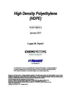
Figure 1 Product Constructions Copper foil
Copper foil
C-Staged Epoxy resin B-Staged Epoxy resin B-Staged Epoxy resin
Dual e Passs
Single Pass
PRODUCT DESCRIPTION Resin coated copper is a unique dielectric material for built-up multilayer circuitry (see Figure 1). Many resin coated foils are available in several configurations with various copper
and dielectric thicknesses, offering balances between the need to fill underlying circuitry while still maintaining the desired dielectric thickness. Single pass resin coated copper consists of a uniquely engineered epoxy resin system coated once onto copper in a semi-cured (B-stage) state. When laminated it has the correct rheology to fill and encapsulate underlying circuitry as well as leave resin behind to function as a dielectric.
Figure 2 Dk / Df as a Function of Frequency (Condition A) 4
0.03
Dk
Df
3.5
0.025
3
0.02
2.5
Dk(RCC) Df(RCC)
2 1E+05
0.015
Dk(Multifoil) Df(Multifoil)
0.01
1E+06
1E+07
1E+08
1E+09
1E+10
Frequency (Hz)
Dual stage, or double pass resin coated copper, consists of copper foil which has two coatings applied to it. The first coating is fully cured, Cstage high temperature epoxy; the second coating is semi-cured, B-stage high temperature epoxy. The C-stage coating acts as the dielectric, electrically insulating the outer layer copper from the adjacent conductive copper layer. The B-stage coating acts as an adhesive to bond the resin coated copper to the innerlayer. During lamination, the B-stage fills the innerlayer circuitry and any buried vias in the innerlayer, while the C-stage acts as a “stop” to produce the desired dielectric thickness between layers 1 and 2 and n and (n-1). RESIN COATED COPPER PROPERTIES Dielectric constant, Dk (or permitivity), is one of the key properties of the PCMCIA card construction materials that has a significant impact on circuit performance. Resin coated copper is non-reinforced so that the Dk value is that of neat resin ≈3.4 (at 1MHz). By contrast, a comparable glass-reinforced construction is 4.3 to 4.5, with this value being heavily influenced by the higher Dk of woven glass fabric. The lower Dk of resin coated copper further enables the use of high speed circuitry. Figure 2 is a graph of both dielectric constant and dissipation factor (Df) as a function of frequency for AlliedSignal's Multifoil and RCC materials. While it is well-recognized that glass is a limiting factor for Dk in traditional laminates, pure resin has a higher Df than glass reinforced constructions.
General product properties of single pass (AlliedSignal’s MultiFoil) and double pass (AlliedSignal’s RCC) are shown in Table below. Table 1
Physical Properties PROPERTY
MULTIFOIL
RCC
UNITS
Glass Transition (Tg) Electric Strength Peel Strength - Condition A - After solder float - At elevated temp. Water absorption (cured resin)
135 1600
160 1800
°C volts/mil
7.8 7.8 7.5 2.2
6.2 6.0 5.4 0.8
lbs/in lbs/in lbs/in %
(D-24/23) 100% RH
APPLICATIONS HDI: Microvias Increased density not only reduces layer counts but enables faster processing speeds. The time it takes electrical signals to travel from device to device dramatically decreases with the increase in board density. While the capacitance of mechanically drilled through holes is approximately 1 picoFarad (pF), the capacitance of laser or plasma ablated blind vias is approximately 0.05pF, about one-twentieth that of through holes. Dense boards which demand such electrical performance will require many blind and buried vias. Economical construction of large numbers of blind vias will require new material solutions, such as those offered by resin coated copper. The all resin construction of resin coated copper allows the capability to create ultra-small vias
(