CHAPTER 6 PICTORIAL SKETCHING
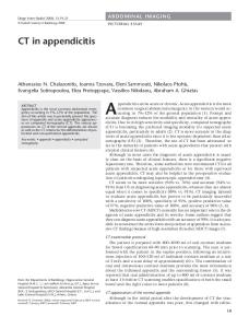
6-1Four Types of Projections
Types of Projections
6-2 Axonometric Projection As shown in figure below, axonometric projections are classified as isometric projection (all axes equally foreshortened), dimetric projection (two axes equally shortened), and trimetric projection (all three axes foreshortened differently, requiring different scales for each axis).
(cont) Figures below show the contrast between an isometric sketch (i.e., drawing) and an isometric projection. The isometric projection is about 25% larger than the isometric projection, but the pictorial value is obviously the same.
When you create isometric sketches, you do not always have to make accurate measurements locating each point in the sketch exactly. Instead, keep your sketch in proportion. Isometric pictorials are great for showing piping layouts and structural designs.
Step by Step 6.1. Isometric Sketching
6-4 Normal and Inclined Surfaces in Isometric View Making an isometric sketch of an object having normal surfaces is shown in figure below. Notice that all measurements are made parallel to the main edges of the enclosing box – that is, parallel to the isometric axes.
(cont) Making an isometric sketch of an object that has inclined surfaces (and oblique edges) is shown below. Notice that inclined surfaces are located by offset, or coordinate measurements along the isometric lines. For example, distances E and F are used to locate the inclined surface M, and distances A and B are used to locate surface N.
6-5 Oblique Surfaces in Isometric View Oblique surfaces in isometric view may be drawn by finding the intersections of the oblique surfaces with isometric planes. For example, in figure (a) the oblique plane contains points A, B, and C. Locate the plane by extending line AB to X and Y, points that share isometric planes with C, as shown in figure (b). Sketch lines XC and YC to locate points E and F. Then draw lines AD and ED, using the rule that parallel lines on the object remain parallel in any view. Figure (c) shows the completed drawing.
6-6 Other Positions of The Isometric Axes Orient your drawing on the isometric axes in the way that shows the part most clearly, without the need for hidden lines. Figure A shows an isotropic view of a birdhouse in two different orientations. The view from below shows more of the details of its construction and therefore may be a better view. If the object is particularly long, orient it horizontally for best effect, as shown in Fig. B.
Fig. A
Fig. B
6-7 Offset Measurements You can locate a new point from an existing corner, as illustrated in the figures below. Box in the main block first, then sketch the offset lines CA and BA to locate the corner A of the small box or the rectangular recess. These are called offset measurements, and since they are parallel to normal edges on the object, they will be parallel to the same edges in the isometric.
Fig. A
Fig. B
6-8 Isometric Ellipses When objects with cylindrical or conical shapers are placed in isometric or other oblique positions, the circles are seen at an angle and appear as ellipses as shown below. When sketching isometric ellipses, the major axis of the ellipse is always at the right angles to the centerline of the cylinder, and the minor axis is at the right angle to the major axis and coincides with the centerline.
6-9 Arcs in Isometric View Figure below shows an isotropic view of an object that has rounded corners. To sketch arcs in an isotropic view, use the radius and block in the ellipse along the appropriate isometric axis lines. In this case the radius R is measured from the construction corner to locate the center of elliptical arc. Notice that the radius R does not remain a constant value when showing the arc in isometric view.
6-10 Isometric Ellipse Templates The template shown below combines the angles foreshortened isometric scales, and ellipses on the same instrument. The ellipses are provided with markings to coincide with the isometric centerlines of the holes – a convenient feature in isometric drawing.
Step by Step 6.2. Sketching Isometric Ellipses
Comparison of Approximate Ellipses in Iso metric Drawings
Click here for simulation of construction
6-11 Sketching on Isometric Paper Follow the steps described in the following figures.
6-12,13. Hidden and Center Lines Hidden lines are omitted in pictorial sketches unless they are need to make the drawing clear. Centerlines are drawn in a pictorial if they are needed to indicate symmetry or if they are needed for dimensioning.
6.14 Nonisometric Lines Since the only lines of an object that are drawn true length in an isometric drawing are the isometric axes or lines drawn parallel to them, nonisometric lines cannot be measured directly.
Thus, use box construction and offset measurements to draw nonisometric lines.
6-15 Angles in Isometric View A regular protractor cannot be used to measure angles in isometric. Angular measurements must be converted to linear measurements along isotropic lines. For example, in the multiview drawing in figure (a), none of the three 60-degree angles will be 60 degree in the isometric drawing. The following shows the drawing procedure.
6-16 Irregular Objects If the general shape of an object is not somewhat rectangular, it may be drawn using box construction.
6-17 Curves in Isometric View Draw curves in isometric sketches by using a series of offset measurements. Select any number of points, such as A, B, and C, randomly along the curve, as shown in the top view in figure below. The more points used, the greater the accuracy.
6-18 Screw Threads in Isometric Parallel partial ellipses are used to present only the crests of a screw thread in isometric view as shown below. The ellipses may be sketched freehand or with an ellipse template.
6-19 The Sphere in Isometric The isometric projection of a sphere is a circle whose diameter is the major axis of the isometric ellipse. Figure (a) shows two views of a sphere enclosed in construction cube. In fig. I the cube is drawn in, together with the isometric of a great circle (cut by a plane through the center) that is parallel to one face of the cube. In fig. II the result is an isometric sketch and its diameter is the square root of 3/2 times the actual diameter of the sphere.
6-20 Isometric Dimensioning Isometric drawing are not usually dimensioned because they do not show object features at true size. ANSI has approved two dimensioning methods --- namely, the pictorial plane, or aligned, system and the unidirectional system – both shown in figure below.
Figures below show correct and incorrect isometric dimensioning.
6-24 Choosing The Angle For Receding Lines The receding lines may be drawn at any convenient angle. Some examples are in figure below. The angle that should be used depends on the shape of the object and location of its features.
For example, in figure (a) below a large angle was used because it gives a better view of the rectangular recess on the top, while in figure (b) a small angle was chosen to show a similar feature on the side.
6-25 Length of Receding Lines Oblique sketches present an unnatural appearance, with more or less serious distortion, depending on the object shown. The appearance of distortion may be reduced by decreasing the length of the receding lines. In figures below, a cube with a hole through the front is shown in five oblique drawing with varying degrees of foreshortening of the receding lines.
6-26 Perspective Sketching Perspective pictorials most closely approximate the view produced by the human eye. Figure below shows a perspective view of an airport produced using CAD.
Perspective pictorials are important in architecture, industrial design, and illustration. Engineers also often need to show pictorial representation of objects and should understand the basic principles of perspective (see ANSI/ASME Y14.4M-1989 (R1994)). Unlike axonometric projection, perspective causes parallel edges to converge at vanishing points. The three types of perspective are one-point, twopoint. and three-point perspective, depending on the number of vanishing points
6.27 General Principles A perspective involves four main elements: (1) the observer’s eye. (2) the object being viewed, (3) the plane of projection, and (4) the projectors from all points on the object to the observer’s eye. In Figure 6.32 the observer is shown looking along a boulevard and through an imaginary plane of projection, the picture plane. The position of the observer’s eye is called the station point, and the lines from station point to the points in the scene are projectors or visual rays.
Collectively the points where the visual rays pierce the picture plane are the perspective view of the object as seen by the observer, which is shown in Figure 6.33.
The line representing the horizon is the edge of the horizon plane, which is parallel to the ground plane and passes through the station point. The horizon is the line of intersection of this plane with the picture plane and represents the eye level of the observer. Notice that lines that are parallel to each other not parallel to the picture plane - such as curb sidewalk lines, and lines along the tops and bottoms the lamp posts - all converge toward a single point on the horizon - the vanishing point of the lines
6.28 Three Types of Perspectives Perspective drawings are classified according to the number of vanishing points required, which in turn on the position of the object with respect to picture plane. If the object sits with one face parallel to the of projection, only one vanishing point is required. The result is a one-point perspective, or perspective. If the object sits at an angle with the picture but with vertical edges parallel to the picture plane, two vanishing points are required, and the a two-point perspective, or an angular perspective. This is the most common type of perspective If the object sits so that no system of parallel edges is parallel to the picture plane, three vanishing points are necessary, and the result is a three-point perspective.
General Steps 1. Place the object on the ground place so that principal faces make certain angles to the picture plane in the top view. 2. Introduce a picture plane (PP) next to the object in the top view. Usually, the PP contains one front edge. 3. Set a station point (SP) in front in the top view where the observer is positioned. 4. Now, in the front view, introduce the horizontal ground line (GL). 5. Above the ground line, introduce the horizon. 6. Draw a parallel line to the principal edge until it intersect the horizon. The intersecting point is the vanishing point. Draw another parallel line if you have another set of parallel lines to get another vanishing point. 7. Connect the station point to points on the object by visual rays and find the piercing points on the picture plane, and then project these points to the front perspective view. The first edge to project is the edge that is contained on PP. This appears true length on the perspective drawing. 8. Draw a set of parallel lines that vanish at the same vanishing point and find the intersections with projection lines at the step 7 above. 9. Connect appropriate points to form lines.
6.30 Two-Point Perspective Two-point perspective is more true to life than one-point perspective. To sketch a two-point perspective, orient the object so that principal edges are vertical and therefore have no vanishing point; edges in the other two directions have vanishing points. Two-point perspectives are especially good for representing buildings and large civil structures, such as dams or bridges. See the next pages for the detailed illustration of how to construct the two-point perspective drawing.
Step by Step 6.5
Example 1
Example 2
Example 3
Example 4. Perspective by Revolution
6.29 One-Point Perspective To sketch a one-point perspective view, orient the object so that a principal face is parallel to the picture plane. If desired, this face can be placed in the picture plane. The other principal face is perpendicular to the picture plane, and its lines will converge toward a single vanishing point.
Step by Step 6.4
6.31 Three-Point Perspective In three-point perspective, the object is placed so that none of its principal edges is parallel to the picture plane. Each of the three sets of parallel edges has a separate vanishing point. Figure 6.34 shows the construction of a three-point perspective.