Chapter 3 Sketching and Lettering
Objectives
Introduction
The student will be able to:
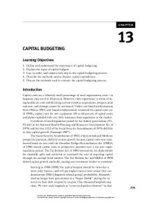
Highly developed manual drafting skills are not required for the preparation of CAD drawings (Fig. 3-1); however, a competent CAD operator must possess a thorough understanding of the principles of drafting and be skilled in technical sketching.
• use proper line weights to sketch and letter • complete a twodimensional sketch of simple objects • complete a threedimensional sketch of simple objects • file a record of sketched ideas • select and sharpen sketching and lettering pencils • keep sketches in proportion • dimension a sketch • shade a sketch • letter clearly on a sketch
Figure 3-1 No manual drafting was required for this CAD-generated working drawing. (Courtesy of Caterpillar Inc.)
Observe how the sketch shown in Figure 3-2 is used to describe the object shown in Figure 3-3.This is another example of the proverb, “A picture is worth a thousand words.”
24
Chapter 3 – Sketching and Lettering
Supplies Sketching supplies consist of a wide variety of pencils, erasers, and drawing media. Soft pencils in the range shown in Figure 3-4 are used for sketching. Pencil points (Fig. 3-5) are rounded for sketching compared to the sharp points used for instrument drawing. However, sharp points on soft pencils are used for layout and Figure 3-2 A freehand sketch is worth a lettering guide line sketching. thousand words. Chisel points are used for shading. Sketching pencils are sharpened with a mechanical sharpener, or 7B 6B 5B 4B 3B 2B B HB F with a knife and file, or sandpaper to shape the point. Although many types of drawing media are used for technical sketch- Figure 3-4 ing, grid paper is the Recommended pencil grades for sketching most practical and easy to use (Fig. 3-6). Grids provide guide lines for rough scaling and proper alignment of perpendicular and parallel lines. Use light-colored surfaces if sketches are to be photocopied, and use translucent surfaces if diazo prints are to be made.Translucent surfaces are also helpful if progressive design sketches are to be traced.
Figure 3-3 An industrial product (Courtesy of Black and Decker U.S. Power Tools Group)
H
POINTED LAYOUT AND GUIDE LINES
Figure 3-6 Drawing on grid paper is faster and neater. (Photo by Ann Ross Wallach)
2H
3H
4H
ROUNDED OBJECT LINES
5H
6H
7H
8H
9H
CHISEL SHADING
Figure 3-5 Recommended pencil points for sketching
25
Fundamentals of Modern Drafting
Working Drawing Sketches Working drawing sketches are used as the major design reference in manufacturing and construction. Sketches are also used as working drawings when time and conditions preclude the preparation of instrument or CAD working drawings.These sketches are usually orthographic multiview drawings, but they are sometimes prepared as pictorial drawings. An orthographic drawing shows several views of an object on a drawing surface that is perpendicular to both the view and the lines of projection. A pictorial drawing shows an object’s depth; three sides of an object can be seen in one view.
Orthographic Multiview Sketches Multiview sketches provide the greatest amount of detail for manufacturing and construction. Figure 3-7 shows the Figure 3-7 steps recommended to Steps to sketch a multiview drawing complete a multiview sketch. As with instrument drawing (see Chapter 18), blocking in the overall outline before completing the internal details is the key to maintaining correct scales, angles, and proportions.
Pictorial Sketches Blocking in the basic outline is also the recommended procedure for pictorial sketches.There are three types of pictorial sketches: isometric, oblique, and perspective. Isometric sketches are prepared by establishing a vertical corner line and projecting receding lines 30° (Fig. 3-8). As with multiview sketches, always block in the entire outline of the object before cutting corners or adding surface details such as holes and projections. Oblique sketches are pictorials that recede on only one side of an orthographic Figure 3-8 Steps to sketch an isometric drawing view. In preparing an oblique sketch, first sketch a front view of the object (Fig. 3-9). Then extend lines from each corner upward at 45° or 30°. Connect the ends of these lines with lines that are parallel to the lines of the 26
Chapter 3 – Sketching and Lettering
front view. Oblique sketches are easy to dimension since the width and length of the front view are sketched to actual scale. Only the depth dimension is foreshortened Figure 3-9 by the receding lines. Steps to sketch an oblique drawing Perspective sketches are pictorials that contain receding sides designed to approximate the actual appearance of an object. There are three types of perspectives: one-point, two-point, and three-point. 1.
2.
One-point perspective sketches are similar to oblique drawings, except the receding lines do not follow a consistent angle. Receding lines are connected to a vanishing point. A vanishing point represents the point at which all receding lines appear to come together. It is similar to road or train tracks disappearing on the horizon. In sketching a one-point perspective, first outline the front view, as in oblique sketching. Establish a vanishing point and sketch lines from each corner to this point (Fig. 3-10). Sketch lines representing the back of the object parallel to the lines on the front view.This blocks in the sketch. Now any angular cuts Figure 3-10 Steps to sketch a one-point perspective drawing and details can be added. Two-point perspective sketches are similar to isometric sketches, except side lines recede to two vanishing points. First sketch the front vertical corner (Fig. 3-11). Establish two vanishing points above or below the front corner line, and connect the top and bottom of the front corner line to each of these points. Vanishing points on two-point perspective sketches must always be located on a horizontal line representing the horizon. Next, establish the depth of the sides and connect the Figure 3-11 Steps to sketch a two-point perspective drawing 27
Fundamentals of Modern Drafting
3.
back corner lines also to the vanishing points. In two-point perspectives, vertical lines are all parallel. In three-point perspectives, vertical lines are projected to a third vanishing point that is aligned with the vertical front corner line.Three-point perspectives are usually used for architectural pictorials, and rarely for technical drawings.
Sketching Guidelines and Procedures
VISIBLE LINE
SECTION LINE
BORDER LINE
HIDDEN LINE
Line conventions and letterCUTTING PLANE LONG BREAK LINE ing for technical sketches are simiSHORT BREAK LINE PHANTOM LINE lar to those used for instrument CENTERLINE LEADER drawings (Fig. 3-12). Sketching DIMENSION/EXTENSION LINES GUIDE LINES/LAYOUT LINES (LIGHT) standards differ only in the degree of line raggedness. Lines are dark and wide for object lines, dark and Figure 3-12 thin for dimension and center Line conventions for sketching working drawings lines, and thin and light for layout and guide lines. Figure 3-13 shows the application of line conventions to a technical sketch. All sketches are comprised of straight lines, circles and arcs, irregular curves, and letters and PHANTOM LINE numerals (Fig. 3-14). Sketches cannot be prepared SHORT BREAK with the precision and accuracy of an instrument CENTERLINE or CAD drawing. Care must be taken to insure VISIBLE LINE that dimensions are relatively proportional. If SECTION LINE dimensional proportions are grossly inaccurate, the sketch will misrepresent the actual appearance of the object (Fig. 3-15). LONG BREAK
LINES
CUTTING PLANE
CIRCLES
HIDDEN LINE GUIDE LINE
CURVES
TEXT
Figure 3-14 Four basic drawing forms make up all drawings. 28
EXTENSION LINE
DIMENSION LINE
Figure 3-13 Using line conventions on a working drawing
Chapter 3 – Sketching and Lettering
When sketching straight lines, squares, and rectangles, use short strokes. Do not attempt to 1 2 3 draw continuous lines. Right-angle lines, unless Figure 3-16 sketched on grid paper, Sketching straight lines, squares, and should be laid out and rectangles sketched (Fig. 3-16). Circles and arcs can be accurately and symmetrically sketched by following the sequence shown in Figure 3-17a. 1 2 3 4 Just as the circle was derived from the square Figure 3-17a in Figure 3-17a, all fillets Sketching circles and rounds should first be blocked in square, as shown in Figure 3-17b. By following this procedure, proper proportions and symmetry can be maintained. The procedure and sequence for sketching ellipses Figure 3-15 is similar to circle sketching Well-proportioned drawings have (Fig. 3-18). Sketching accurate superior communication. angles, other than right angles (90°), can be difficult without using a triangle or protractor; however, by estimating and dividing a right angle into even angles, you can achieve 1 an acceptable level of accuracy (Fig. 3-19). When sketching, hold the pencil comfortably (Fig. 3-20) and pull it (Fig. 3-21), never 1 2 push it.To maintain a consistently rounded point and avoid wearing a flat chisel 2 3 4 point, rotate the pencil frequently (Fig. 3-22).When erasing soft pencil sketches, use a Figure 3-17b Figure 3-18 Sketching fillets and rounds Sketching ellipses good quality medium-soft eraser. 29
Fundamentals of Modern Drafting
1
3
2
4
Figure 3-19 Sketching and estimating angles
Shading Surfaces exposed to a major light source will appear bright. Conversely, surfaces not directly exposed to a light source will be shaded; therefore, adding shading to sketches creates realism (Fig. 3-23). In Figure 3-23, the light source is located above and to the left of the object. The opposite areas are shaded because direct light is blocked from these surfaces. Figure 3-24 shows techniques for shadowing (shading) these areas. Surfaces are rarely totally hidden from a light source. Some surfaces are very light, very dark, or appear in a variety of shadow grades depending on the position, intensity, and number of light sources. Figure 3-25 shows an object with three light levels: light, medium, and dark. In addition, this figure shows a separate shadow cast by the object.
30
Figure 3-20 Use a comfortable pencil grip for sketching. (Photo by Ann Ross Wallach)
DRAW THE PENCIL
Figure 3-21 Always pull the pencil—never push it.
Figure 3-22 Rotate the pencil frequently for rounded points.
Figure 3-23 Shade (darken) the surfaces opposite the light source.
Chapter 3 – Sketching and Lettering
LIGHT SOURCE
DARK SOLID
GRAY CLOSE LINES
LIGHT GRAY SPACED LINES
TEXTURE
STIPPLE
BLANK HIGH LIGHT
Figure 3-25 The light source dictates the position of the shadows.
Figure 3-24 Shading techniques
Light travels in a straight line and cannot bend around corners unless reflected; therefore, light intensity on surfaces always changes at the corners of objects. Figure 3-26 shows several methods of sketching these differences to add realism to a sketch. On objects without corners, such as spheres and cylinders, light and dark areas change gradually. Figure 3-27 shows several methods of shadowing a cylinder sketch to add realism.
Dimensioning
Figure 3-26
When sketches are used for instruction, manufacturFreehand shading of sharp corners ing, or construction, dimensions are usually necessary to adequately describe the object.When sketches are dimensioned, the overall width, depth, and height dimensions are placed on the outside of the location dimensions (Fig. 3-28).These are known as overall dimensions. Dimension lines are sketched parallel to object lines and connected to the object with extension lines and arrows. Location dimensions show the location of parts of an object. Size dimensions show the size of any hole or projection on the object and are placed between the object and the overall dimension lines. Dimensions are usually shown on multiview sketches. Pictorial sketches Figure 3-27 Freehand shading of rounded surfaces (Fig. 3-29) are normally used only to show the general appearance of products and do not require dimensions.
31
Fundamentals of Modern Drafting
O S
O
O S
L L
S
O = OVERALL DIMENSION L = LOCATION DIMENSION S = SIZE DIMENSION
Figure 3-28 Types of dimensions
Figure 3-29 Examples of pictorial sketches
Lettering Some information is best communicated with words or numerals. Almost every sketch or drawing contains notes, labels, and dimensions that must be legible and consistent. In Figure 3-30, the title, material, and hole size are described with a lettered notation. Each numeral used for dimensioning must be distinct from all other numerals.The letter D which looks like an O, or the numeral 3, which looks like an 8, can be easily misread and create costly manufacturing or construction mistakes. For this reason, the American Society of Mechanical Engineers (ASME) style of letters and numerals (Fig. 3-31) is used by most American industries. Figure 3-32 shows the most efficient and quickest method of making these letters and numerals. A slanted Figure 3-30 form of this style (Fig. 3-33) is acceptable but is rarely used or rec- Working drawing sketch with dimensions and notations ommended for engineering drawings. To letter most efficiently and legibly, always use guide lines (Fig. 3-34). Guide lines keep letters consistent and contained in the area selected. As a general rule, most lettering is 1/8" high with 3/16" high title headings. Drawings to be microfilmed should be 3/16" or 1/4" high, using the microfont style shown in Figure 3-35. Correct spacing between letters is also needed to produce lettering that is most readable. Figure 3-36 shows lettering that has the area between the letters approximately equal. By contrast, Figure 3-37 shows wide and inconsistent spacing of letters. Notice how difficult it is to quickly read Figure 3-37 compared to Figure 3-36. Spacing Figure 3-31 between words and sentences is also important for effective reading. Single-stroke vertical Gothic lettering (ASME standards) 32
Chapter 3 – Sketching and Lettering
Figure 3-32 Recommended lettering strokes
Figure 3-33 Single-stroke slant (68°) Gothic lettering
Figure 3-34 Guide lines will aid freehand lettering.
The space between words should be approximately equal to the height of the letters.The space between sentences should be twice the height of the letters (Fig. 3-38). Fractions are among the most frequent causes of dimensional errors. If a numerator or denominator is misread as a whole number, the result can be disastrous. For this reason, the ASME spacing for fractions (Fig. 3-39) should be used to avoid confusion. When all of the procedures and guidelines for sketching are combined, the result can be a readable and functional technical sketch as shown at the left in Figure 3-40. If these guidelines are ignored, the confusing series of lines and letters shown at right in Figure 3-40 can result.
Figure 3-35 Microfont lettering is recommended if drawing is to be microfilmed. 33
Fundamentals of Modern Drafting
FUNDAMENTALS OF DRAFTING WITH AUTOCAD
FU NDAM ENTAL S O F DRAF T IN G WI TH AU TOC A D
Figure 3-36 The area between letters should be as equal as possible.
Figure 3-37 Inconsistent areas between letters create reading difficulties.
TWICE HEIGHT OF LETTER
THIS IS AN ENGINEERING TEXT FOR DRAFTING STUDENTS. ALL DIMENSIONS ARE IN INCHES. HEIGHT OF LETTER
Figure 3-38 Spacing between words and sentences
Figure 3-39 Fractions on the working drawing
Figure 3-40 Which sketch gives better communication?
Drafting Exercises 1.
2. 34
Sketch the isometric drawings in Figures 3-41 through 3-47 on isometric grid paper. Sketch the multiview drawings in Figure 3-48.
3.
Sketch the pickup truck in
6.
Practice lettering singlestroke Gothic lettering on 1/8" grid paper.
7.
Practice placing various types of fonts in different sizes and angular positions with a CAD system.
Figure 3-49.
4. 5.
Sketch the objects in Figure 3-50. Sketch the tool-bit holder in Figure 3-51.
8
9
10
6
7
4
5
2
3
1
0
1
2
3
4
5
6
7
8
9
10
8
9
10
6
7
4
5
2
3
1
0
1
2
3
4
5
6
7
8
9
10
10
10
10
10
9
9
9
9
8
8
8
8
7
7
7
7
6 5
6 5
6 5
6 5
4
4
4
4
3
3
3
3
2
2
2
2
1
1
1
1
0
0
0
1
2
3
4
5
6
7
8
9
10
10
7
8
9
5
6
2
3
4
1
9
10
2
3
4
5
6
7
8
9
10
7
8
9
10
5
6
2
3
4
1
Figure 3-42
Figure 3-41
2
3
4
5
6
7
8
0 1
1
0
1
2
3
4
5
6
7
8
9
10
10
8
9
6
7
4
5
2
3
1
0
1
2
3
4
5
6
7
8
9
10
10
10
10
10
9
9
9
9
8
8
8
8
7
7
7
7
6 5
6 5
6 5
6 5
4
4
4
4
3
3
3
3
2
2
2
2
1
1
1
0
0
0 1
2
3
4
5
6
7
8
9
10
10
9
7
8
5
6
2
3
4
1
9
10
0 2
3
4
5
6
7
8
9
10
10
9
8
5
6
7
2
3
4
1
Figure 3-44
Figure 3-43
2
3
4
5
6
7
8
1 1
1
0
1
2
3
4
5
6
7
8
9
10
10
7
8
9
6
3
4
5
2
1
0
1
2
3
4
5
6
7
8
9
10
10
10
10
10
9
9
9
9
8
8
8
8
7
7
7
7
6 5
6 5
6 5
6 5
4
4
4
4
3
3
3
3
2
2
2
2
1
1
1
0
0
0 1
2
3
4
Figure 3-45
5
6
7
8
9
10
10
9
8
7
6
5
4
3
2
1
1 0 1
2
3
4
5
6
7
8
9
10
10
9
8
7
6
5
4
3
2
1
Figure 3-46 35
Fundamentals of Modern Drafting
Figure 3-47 Isometric sketching practice
Figure 3-48 Orthographic multiview sketching practice 36
Chapter 3 – Sketching and Lettering
Figure 3-49 Follow the steps to sketch the pickup. 37
Fundamentals of Modern Drafting
Figure 3-50 Sketching practice with real objects
2
HANDLE
4
1
2
4 CHUCK
3
3
Figure 3-51 Sketch the tool-bit holder.
38
CHUCK COLLAR
SPRING
Chapter 3 – Sketching and Lettering
Design Exercises 1.
Redesign and sketch the hexagon wrench in Figure 3-52.
2.
Sketch the bookend in
3.
Design a new tent stake as specified in Figure 3-54.
4.
Select one or more of the industrial products in Figure 3-55 and sketch a new design.
Figure 3-53 and design
your stylized initials into the surface.
2X .5
7.75 2X .5
Figure 3-52 Redesign and sketch the hexagon wrench.
4.75 3.0 MAT’L .5" THK WOOD BOOKEND
Figure 3-53 Sketch the bookend with your initials.
Figure 3-54 39
Fundamentals of Modern Drafting
Ink Pens
Clock Radio
Tractor
Desk Calculator
Hand Calculator
Space Station Supersonic Rocket
Sports Car Portable Radio
Pencil Sharpener
Robot Sewing Machine
Orbital Handsander
Power Handsaw Figure 3-55 Sketch a new design for one or more of these industrial products.
Key Terms American Society of Mechanical Engineers (ASME) Grid paper Guide lines Isometric Line conventions Location dimensions 40
Microfont Multiview Oblique One-point perspective Orthographic Overall dimensions Perspective
Pictorial Shading Size dimensions Three-point perspective Two-point perspective Vanishing point Working drawing