Chapter 19 Electric Charges, Forces, and Fields Outline 19-1
Electric Charge
19-2
Insulators and Conductors
19-3
Coulomb’s Law
19-4
The Electric Field
19-5
Electric Field Lines
19-6
Shield and Charging by Induction
19-7
Electric Flux (and Gauss’s Law)
19-6
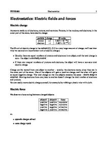
Shielding and Charging by Induction Figure 19-18 Charge Distribution on a Conducting Sphere Which one is correct? a) Charge Distributed uniformly on the surface of a Conducting Sphere.
b) Charge Distributed uniformly through the volume of a Conducting Sphere.
Excess Charge on a Conductor Excess charges (positive or negative) placed on a conductor should move to the exterior surface of the conductor.
A. Shielding Figure 19-19. Electric Field Near a Conducting Surface
(a) E=0 in the conductor. The charges are induced by the outside field
(b) Electric field lines meet the surface at right angles.
Zero Field within a Conductor
Zero Field within a Conductor When electric charges are at rest, the electric field within a conductor is zero, E = 0; Note: The conclusion is also hold true for a hollow conductor. Applications: Sensitive electronic equipment can be enclosed in a metal box to isolate from the exterior electric field, since the electric field in the metal box is 0.
Electric Field at Conductor Surface Electric field lines contact conductor surface at right angle.
B. Charging by Induction
For an electric neutral object, there are two ways to charge the object: 1) By Touching 2) No physics touching: By induction. since electric field can act at a distance!
Figure 19-22 (a, b) Charging by Induction amber
a). A charged rod induces + and – charge on opposite sides of the conductor.
amber
b). When the conductor is grounded, the – charges are transferred.
Figure 19-22 (c, d) Charging by Induction
c). Removing the ground line, the conductor has net + charges
d). The charges are uniformly distributed on the conductor, and the charges are opposite in sign to that of the rod.
Charging by Induction A electric charge can create a local opposite charge on a conductor at some distance away, without contacting the conductor (since the electric charge create an electric field).
19-7 Electric Flux and Gauss’s Law
Electric Flux Definition of Electric Flux, Φ
Φ = EA cos θ
(19 − 11)
SI unit: N.M2/C Where, E is (uniform) electric field. A is the area.
θ
is the angle between
JG E and the normal of
the area A.
19-23. Definition of Electric Flux
Figure 19-23 (a, b) Electric Flux
(a)
(b)
Φ = EA
Φ=0
The sign of the Flux is defined as
1) The flux is positive for field lines that leave the enclosed volume of the surface.
2) The flux is negative for field lines that enter the enclosed volume of the surface.
Example 19-49
Plane Surface Flux
A uniform electric field of magnitude 25,000 N/C makes an angle of 27° with a plane surface of area 0.133m. What is the electric flux through this surface?
Example
Plane Surface Flux
A uniform electric field of magnitude 25,000 N/C makes an angle of 27° with a plane surface of area 0.0133m. What is the electric flux through this surface?
Solution:
Φ = EA cos θ = 25, 000 × 0.0133 × cos(90° − 27°) = 1.51× 10²
N.M2/C
Gauss’s Law If a charge q is enclosed by an arbitrary surface, the electric flux, Φ, is
Φ= Where
ε0 =
q
(19 − 13)
ε0 1 4π k
= 8.85 × 10⁻¹² C / N .m 2
is the permittivity of free space. Note: Gauss’s law holds true for any arbitrary surface.
Figure 19-24 Electric Flux for a Point Charge
The electric flux through a spherical surface surrounding a positive point charge q. The electric flux for arbitrary surface is the same as for the sphere.
Deriving Gauss’s Law 1)
For a positive point source charge q, as shown in19-24, the surface of a sphere has a constant magnitude
q E=k 2 r 2) Since the electric field is perpendicular to the spherical surface, the flux is simple the E times the area A Φ = EA = (k =
q
ε0
q 2 )(4 π r ) = 4π kq 2 r
Gauss’s Law applied to a metal spherical shell A case with three Gaussian surfaces.
Figure 19-25 Gauss’s Law Applied to a Spherical Shell
Case 1 at r1< RA Gaussian surface: what is the electric flux and the magnitude of the electric field ? The electric flux at r1 is
Φ = E (4π r12 ) = Q / ε 0 Therefore, the magnitude of the electric field is E=
Q 4πε 0 r 2
=k
Q r2
The charges on the shell do not affect the electric flux of this Gaussian surface!
Case 2 at RA < r1 < RB Gaussian surface: what is the electric flux and the magnitude of the electric field ? Sine E is zero (E=0) in a conductor, the electric flux at r1 is
Φ = EA = 0
The net charge in this Gaussian surface is zero; This also means that the induced charge on the inner surface of the shell is –Q.
Case 3 at r1 > RB Gaussian surface: what is the electric flux and the magnitude of the electric field ? The electric flux at r1 is Φ = E (4π r12 ) = (enclosed ch arg e) / ε 0 = Q / ε0 Q
Q =k 2 E= 2 4πε 0 r3 r3 The electric field outside the shell is the same as if the shell were not present; The conducting shelling does not shield the extend world from charges within it.
Active Example 19-3 Find the Electric Field Use the cylindrical Gaussian surface shown in the figure to calculate the electric field between two metal plates of the capacitor. Each plate has a charge per area of magnitude σ
Active Example 19-3 Find the Electric Field
Solution 1) Calculate the electric flux through the curved surface of the cylinder Φ1=0 2) Calculate the electric flux through the two end caps of the cylinder Φ2 =0+EA 3) The total electric flux is Φ = Φ1 + Φ2 =EA 4) The charge enclosed by the cylinder is σA 5) Applied Gauss’s law
Φ=
q
ε0
6) With 3) and 5), we have
E=
=
σ ε0
σA ε0
Summary Shield and Charging by Induction Excess charge: any excess charge move to conductor’s exterior surface, at right angle Zero field is a conductor: The electric field within a conductor is in equilibrium zero. Shielding: A conductor shields a cavity within it from the external electric field;
Electric Flux and Gauss’s Law Φ= EAcosθ Φ=
q
ε0
(19−11) (19 − 13)