Application Note Laser Diode
CAN packaged Laser Diode Series Introduction
Package type
Panasonic offers a series of dualwavelength and single-wavelength laser diode (LD) realized by the proprietary MOCVD fabrication technology. The LD, which emits 660nm and/or 780nm laser light, is assembled in a versatile TO-56 CAN package.
The Panasonic can provide two main types of LD package. One is a can type package and the other is an open-type frame package. In this note we provide explanations about a versatile TO56 CAN type packaged LD series. Please pay attention to the following points to make use of these advantages and ensure highly reliable operation.
Precautions for ESD (Electro Static Discharge) and surge stress
Application Information technology Optical disk drive Laser printer Sensing Distance meter Barcode reader Motion sensor Industrial use Plant factory Bio-Medical Flow cytometry
Laser rank The products are ranked “Class IIIb laser” according to IEC60825-1 and JIS standard 6802 “Laser Product Emission Safety Standards”, and can be hazardous to the human eyes, so that safety protection is necessary when laser beam is radiated.
A laser diode (LD) is one of the most sensitive devices to ESD and electrical surge, so that strict precautions are required when using LDs. If electric pulses that may cause optical emission over the absolute maximum ratings of a laser power are applied to a LD, the LD will be damaged by its own light intensity, resulting in degradation in a short period. Therefore, taking all possible measures against ESD and electrical surge for LD usage is strongly required at the design stage and production line. Please insert an appropriate protection circuit in the drive circuit of LD, check the whole drive circuits including machine power supply, and take appropriate steps, in order that spike noises generated by turning on/off the power supply do not exceed the absolute maximum rating of LD. There is a possibility of laser destruction by unexpected electrical pulses generated by nearby equipment. Please avoid turning on/off a fluorescent lamp or other measurement equipment etc., near LD products. Page 1 of 6
Application Note Laser Diode
CAN packaged Laser Diode Series Please take the following measures to prevent a LD from breaking by ESD when handling : ・Using a wrist band (through 1 MΩ) ・Setting conductive mats on the floor and work tables ・Wearing conductive work uniforms and shoes ・Grounding the tip of a solder iron Use of an ionizer and control of humidity and temperature are recommended especially in a facility or environment where static electrical charge can be easily generated.
Mounting
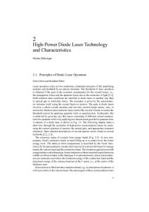
To obtain the specified output power and a long lifetime of the LD an appropriate heat dissipation design is required. In applications using a heat sink, the most effective way to dissipate heat is bringing the heat sink into contact with the backside of the base plate. In Fig.2 the influence of heat dissipation condition for the output power versus operating current is shown for a RED laser diode. If inadequate thermal management is used, the saturated output power can be less than half of that when appropriate thermal management is used.
Heat Sink / Peltier element Cap Base plate
Mounting of a LD should be done at the base plate of the TO package. The cap, should not be exposed to any excess mechanical stress. To prevent breakage of the hermetic seal of the lead pins, the LD’s lead pins and base plate should not be stressed excessively during mounting. Any deformation of the base plate has to be prevented. Reference surface for positioning the LD is the front side and circumference of the base plate.
Lead pins
Heat sink design of LD As the case temperature of LD becomes higher, the life of LD becomes shorter. It is important that an appropriate design is used for the heat dissipation. Mounting example of CAN packaged LD is shown in Fig.1.
Reference surfaces
Fig.1 Mounting example of to56 package
Page 2 of 6
Application Note Laser Diode
CAN packaged Laser Diode Series 800
400
CW Wavelength (nm)
Appropriate heat dissipation Inadequate heat dissipation
300 200 100
795 790 785
5mW 50mW 100mW 150mW 200mW
780 775 770 0
0 0
200
400
600
800
20
40
60
80
CaseTemperature (deg)
1000
(a) 670
Operating current (mA)
Fig.2 Output power examples depending on thermal conditions of RED laser diode (LNCQ28PS01WW).
If a laser diode does not reach the specified optical output power at the specified maximum operating current, please review your cooling system.
CW Wavelength (nm)
Output power (mW)
500
665 5mW 20mW 40mW 60mW 80mW 100mW
660
655 0
20
40
60
80
CaseTemperature (deg)
(b)
Wavelength shift The shift of the emission wavelength with temperature is around 0.25 nm/Kelvin for IR laser diodes and is around 0.2 nm/Kelvin for RED laser diodes. The wavelength shift at different temperatures and output powers are shown in Fig.3 (a) for the IR laser diode LNC728PS01WW and in Fig.3 (b) for RED laser diode LNCQ28PS01WW. In these measurements, the laser diode is appropriately temperature-controlled by a peltier element. These shifts of the wavelength are also depend on the heat sink design and thermal condition.
Fig.3 Wavelength shift depending on case Temperature for (a) IR laser LNC728PS01WW and for (b) RED laser LNCQ28PS01WW .
LD driving To operate an LD, constant and/or modulated current source is required, because LD is a current-driven device. The current source must have very low switching noise characteristics to prevent LD degradation due to surge currents associated with turning on/off of the electrical power. Page 3 of 6
Application Note Laser Diode
CAN packaged Laser Diode Series As temperature changes, optical output power from LD for a given current will change. Therefore, automated power control (APC) function is necessary for applications that require a constant output power over a wide rage of temperatures. Usually, a photodiode (PD) is used to monitor the power. The signal from the PD will be fed back to the current source to maintain the output power from LD at a constant level. Depending on the application type, LD driving current source should be selected, from the viewpoints of maximum current, maximum voltage, and with or without modulation and APC function.
RED LD (anode)
RED LD side
Lw
R1
R1 Cp
R3 R4
To assist with the selection of the LD driving current source, an equivalent circuit of Panasonic CAN packaged LD is shown in Fig.4. LD parameters are calculated by fitting with actual Sparameter measurement result. Table 1 shows typical values under the condition of room temperature and 3mW output power from LD. These values are generally dependent on the temperature and injection current. Therefore, confirmation of matching between LD and the peripheral circuit is recommended.
L1
L1
R4
Lw
Cp
R3
R2 R2 R5
R5 Cd1 Cd2
Cd2 Cd1
L2
Common (Cathode)
Fig. 4 Equivalent circuit of dual wavelength LD
Table 1 Parameter list of equivalent circuit e.g. LNCT28PS01WW parameter
Equivalent circuit
IR LD (anode)
IR LD side
LNCT28PS01WW RED-LD
IR-LD
R2
4.1Ω
4.6Ω
R3
395.0Ω
155.0Ω
R4
1.2Ω
1.3Ω
L1
0.30nH
0.25nH
Cd1
54.5pF
50.5pF
Cd2
28.0pF
29.0pF
R1
≒0.6Ω
≒0.6Ω
R5
1.3Ω
1.3Ω
L2
2.2nH
2.2nH
Lw
≒2.2nH
≒2.2nH
Cp
≒1.44pF
≒1.44pF
Optical design Collimating, focusing or spreading the output light beam from LD is realized by using lens systems. Important factors of the lens are wavelength, numerical aperture, focal length, working distance, and so on. Divergence angles of laser beam also need to be taken into account. Page 4 of 6
Application Note Laser Diode
CAN packaged Laser Diode Series Precaution at soldering
Mechanical stress
Please pay special attention to any temperature rise when heating the solder. Excess heating to laser diode package during soldering may affect eutectic solder and/or laser diode itself. Soldering must be done as quickly as possible with controlling the heating temperature. Lead (terminal) soldering with appropriate cooling time is strongly recommended. Also soldering position of lead(terminal) is recommended to be more than 2mm away from the package body. It is recommended to solder only one lead(terminal) at a time for a short period of time (after heating one lead with solder iron or laser beam etc., cooling down, then, heat another lead). Heating all the leads at once should be avoided. In addition, it is recommended to radiate heat by placing the package on a heat sink, because the package temperature becomes too high even when the lead alone is heated. Please note that when a LD is exposed to mechanical stress like vibration etc. at high temperatures when soldering, the stress may affect the package, leading to possible change of LD characteristics.
Pressure to package This product is hermetic-sealed from the atmosphere with metallic cap and window-glass. Excess mechanical stress may cause mechanical damage to the window-glass and/or breakage of the sealing, which will extremely shortening the lifetime of a LD. Special care should be taken to avoid excess mechanical stress to the LD package when attaching it to a heat sink.
・Soldering temperature, time and position Temperature : Below 350℃ Time : Within 5sec (less than 3sec recommended) Soldering position : 2mm away from package body
Lead forming and cutting Basically lead(terminal) is recommended to use with same condition as shipment. However, some sort of modification of lead forming or cutting may be required for its application. In such cases, please keep the following cautions. Lead forming is recommended to be 2.6mm away from the package body in order to avoid additional mechanical stress to the hermetic sealing. Also, lead forming or cutting has to be carried out at the room temperature before soldering. The forming and cutting process at high temperature may put thermal and mechanical stresses in the package, which cause severe degradation of laser diode characteristics. Panasonic shall not be responsible for any failures and damages caused by customers lead forming and cutting process.
Page 5 of 6
Application Note Laser Diode
CAN packaged Laser Diode Series Panasonic shall not be responsible for any failure due to lead processing at customer’s site.
Others
Storage condition (in-process)
Laser beam is very harmful to the human eyes, therefore, do not look at the light emission directly or through lens, when the laser is in operation.
The surface of package lead(terminal) is metallic plated to ensure good soldering and good electrical contact. Corrosive atmosphere during storage is likely to change its surface characteristics. From this view point, this product is packed in a damp-proof aluminum laminated bag to assure its quality at the shipment. In case of long-period storage after opening damp-proof packing, remaining devices should be used at least within one year to keep its quality. After opening the packing, a recommended storage condition until next mounting is in the ranges of 5~35℃ and 45~75%RH.
This product is designed for normal use; general electronic equipment (e.g. office, communication, measuring equipment or home electric appliance etc.). If you consider the particular use (aero, space, traffic, combustion or safety equipment etc.) requiring specific quality and reliability, which may threaten human life or body in case of its accidents or errors, or the use which is out of the intended normal use, please consult our sales representatives. We shall not be responsible for any failure caused by the use outside the scope of our warranty. There is a possibility that volatile gas generated from something like adhesive or grease can exert a bad influence on the characteristics of LD. We recommend you assess potential risks of outgassing material under the actual condition of use.
Page 6 of 6
Caution for Safety ¢ This product contains Gallium Arsenide (GaAs).
DANGER
GaAs powder and vapor are hazardous to human health if inhaled or ingested. Do not burn, destroy, cut, cleave off, or chemically dissolve the product. Follow related laws and ordinances for disposal. The product should be excluded from general industrial waste or household garbage.
¢ Do not touch or look into the laser beam directly. The laser beam may cause injury to the eye or skin, or loss of eyesight.
Request for your special attention and precautions in using the technical information and semiconductors described in this book (1) If any of the products or technical information described in this book is to be exported or provided to non-residents, the laws and regulations of the exporting country, especially, those with regard to security export control, must be observed. (2) The technical information described in this book is intended only to show the main characteristics and application circuit examples of the products. No license is granted in and to any intellectual property right or other right owned by Panasonic Corporation or any other company. Therefore, no responsibility is assumed by our company as to the infringement upon any such right owned by any other company which may arise as a result of the use of technical information described in this book. (3) The products described in this book are intended to be used for general applications (such as office equipment, communications equipment, measuring instruments and household appliances), or for specific applications as expressly stated in this book. Consult our sales staff in advance for information on the following applications: – Special applications (such as for airplanes, aerospace, automotive equipment, traffic signaling equipment, combustion equipment, life support systems and safety devices) in which exceptional quality and reliability are required, or if the failure or malfunction of the products may directly jeopardize life or harm the human body. It is to be understood that our company shall not be held responsible for any damage incurred as a result of or in connection with your using the products described in this book for any special application, unless our company agrees to your using the products in this book for any special application. (4) The products and product specifications described in this book are subject to change without notice for modification and/or improvement. At the final stage of your design, purchasing, or use of the products, therefore, ask for the most up-to-date Product Standards in advance to make sure that the latest specifications satisfy your requirements. (5) When designing your equipment, comply with the range of absolute maximum rating and the guaranteed operating conditions (operating power supply voltage and operating environment etc.). Especially, please be careful not to exceed the range of absolute maximum rating on the transient state, such as power-on, power-off and mode-switching. Otherwise, we will not be liable for any defect which may arise later in your equipment. Even when the products are used within the guaranteed values, take into the consideration of incidence of break down and failure mode, possible to occur to semiconductor products. Measures on the systems such as redundant design, arresting the spread of fire or preventing glitch are recommended in order to prevent physical injury, fire, social damages, for example, by using the products. (6) Comply with the instructions for use in order to prevent breakdown and characteristics change due to external factors (ESD, EOS, thermal stress and mechanical stress) at the time of handling, mounting or at customer's process. When using products for which damp-proof packing is required, satisfy the conditions, such as shelf life and the elapsed time since first opening the packages. (7) This book may be not reprinted or reproduced whether wholly or partially, without the prior written permission of our company.