BASIC Stamp I Application Notes
1: LCD User-Interface Terminal
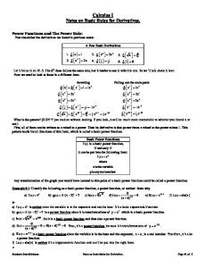
Introduction. This application note presents a program in PBASIC that enables the BASIC Stamp to operate as a simple user-interface terminal. Background. Many systems use a central host computer to control remote functions. At various locations, users communicate with the main system via small terminals that display system status and accept inputs. The BASIC Stamp’s ease of programming and built-in support for serial communications make it a good candidate for such userinterface applications. The liquid-crystal display (LCD) used in this project is based on the popular Hitachi 44780 controller IC. These chips are at the heart of LCD’s ranging in size from two lines of four characters (2x4) to 2x40. How it works. When power is first applied, the BASIC program initializes the LCD. It sets the display to print from left to right, and enables an underline cursor. To eliminate any stray characters, the program clears the screen. After initialization, the program enters a loop waiting for the arrival of a character via the 2400-baud RS-232 interface. When a character arrives, it is checked against a short list of special characters (backspace, control-C, and return). If it is not one of these, the program prints it on the display, and re-enters the waiting-for-data loop. If a backspace is received, the program moves the LCD cursor back one
SWITCHES 0–3
(C) 1992 Parallax, Inc.
EEPROM
PIC16C56
PC
BASIC STAMP
+5V
1k
Vin
0 1 2 3 4 5 6 7
11 12 13 14 4 6
DB4 DB5 DB6 DB7 RS E
Vdd Vo Vss R/W DB0 DB1 DB2 DB3 2
3
1
5
7
8
9
10
GND
+5 10k 1k
22k
10k (contrast)
SERIAL OUT SERIAL IN
Schematic to accompany program
TERMINAL. BAS .
Parallax, Inc. • BASIC Stamp Programming Manual 1.9 • Page 71
1
BASIC Stamp I Application Notes
1: LCD User-Interface Terminal
space, prints a blank (space) character to blot out the character that was there, and then moves back again. The second move-back step is necessary because the LCD automatically advances the cursor. If a control-C is received, the program issues a clear instruction to the LCD, which responds by filling the screen with blanks, and returning the cursor to the leftmost position. If a return character is received, the program interprets the message as a query requiring a response from the user. It enters a loop waiting for the user to press one of the four pushbuttons. When he does, the program sends the character (“0” through “3”) representing the button number back to the host system. It then re-enters its waiting loop. Because of all this processing, the user interface cannot receive characters sent rapidly at the full baud rate. The host program must put a little breathing space between characters; perhaps a 3-millisecond delay. If you reduce the baud rate to 300 baud and set the host terminal to 1.5 or 2 stop bits, you may avoid the need to program a delay. At the beginning of the program, during the initialization of the LCD, you may have noticed that several instructions are repeated, instead of being enclosed in for/next loops. This is not an oversight. Watching the downloading bar graph indicated that the repeated instructions actually resulted in a more compact program from the Stamp’s point of view. Keep an eye on that graph when running programs; it a good relative indication of how much program space you’ve used. The terminal program occupies about two-thirds of the Stamp’s EEPROM. From an electronic standpoint, the circuit employs a couple of tricks. The first involves the RS-232 communication. The Stamp’s processor, a PIC 16C56, is equipped with hefty static-protection diodes on its input/ output pins. When the Stamp receives RS-232 data, which typically swings between -12 and +12 volts (V), these diodes serve to limit the voltage actually seen by the PIC’s internal circuitry to 0 and +5V. The 22k resistor limits the current through the diodes to prevent damage. Sending serial output without an external driver circuit exploits another loophole in the RS-232 standard. While most RS-232 devices
Page 72 • BASIC Stamp Programming Manual 1.9 • Parallax, Inc.
1: LCD User-Interface Terminal
BASIC Stamp I Application Notes
expect the signal to swing between at least -3 and +3V, most will accept the 0 and +5V output of the PIC without problems. This setup is less noise-immune than circuits that play by the RS-232 rules. If you add a line driver/receiver such as a Maxim MAX232, remember that these devices also invert the signals. You’ll have to change the baud/mode parameter in the instructions serin and serout to T2400, where T stands for true signal polarity. If industrial-strength noise immunity is required, or the interface will be at the end of a milelong stretch of wire, use an RS-422 driver/receiver. This will require the same changes to serin and serout. Another trick allows the sharing of input/output pins between the LCD and the pushbuttons. What happens if the user presses the buttons while the LCD is receiving data? Nothing. The Stamp can sink enough current to prevent the 1k pullup resistors from affecting the state of its active output lines. And when the Stamp is receiving input from the switches, the LCD is disabled, so its data lines are in a high-impedance state that’s the next best thing to not being there. These facts allow the LCD and the switches to share the data lines without interference. Finally, note that the resistors are shown on the data side of the switches, not on the +5V side. This is an inexpensive precaution against damage or interference due to electrostatic discharge from the user’s fingertips. It’s not an especially effective precaution, but the price is right. Program listing. These programs may be downloaded from our Internet ftp site at ftp.parallaxinc.com. The ftp site may be reached directly or through our web site at http://www.parallaxinc.com. ' PROGRAM: Terminal.bas ' The Stamp serves as a user-interface terminal. It accepts text via RS-232 from a ' host, and provides a way for the user to respond to queries via four pushbuttons. Symbol S_in Symbol S_out Symbol E Symbol RS Symbol keys Symbol char
= = = = = =
6 7 5 4 b0 b3
' Serial data input pin ' Serial data output pin ' Enable pin, 1 = enabled ' Register select pin, 0 = instruction ' Variable holding # of key pressed. ' Character sent to LCD.
Parallax, Inc. • BASIC Stamp Programming Manual 1.9 • Page 73
1
BASIC Stamp I Application Notes Symbol Symbol Symbol Symbol
Sw_0 Sw_1 Sw_2 Sw_3
= = = =
pin0 pin1 pin2 pin3
1: LCD User-Interface Terminal
' User input switches ' multiplexed w/LCD data lines.
' Set up the Stamp’s I/O lines and initialize the LCD. begin: let pins = 0 ' Clear the output lines let dirs = %01111111 ' One input, 7 outputs. pause 200 ' Wait 200 ms for LCD to reset. ' Initialize the LCD in accordance with Hitachi’s instructions for 4-bit interface. i_LCD: let pins = %00000011 ' Set to 8-bit operation. pulsout E,1 ' Send data three times pause 10 ' to initialize LCD. pulsout E,1 pause 10 pulsout E,1 pause 10 let pins = %00000010 ' Set to 4-bit operation. pulsout E,1 ' Send above data three times. pulsout E,1 pulsout E,1 let char = 14 ' Set up LCD in accordance with gosub wr_LCD ' Hitachi instruction manual. let char = 6 ' Turn on cursor and enable gosub wr_LCD ' left-to-right printing. let char = 1 ' Clear the display. gosub wr_LCD high RS ' Prepare to send characters. ' Main program loop: receive data, check for backspace, and display data on LCD. main: serin S_in,N2400,char ' Main terminal loop. goto bksp out: gosub wr_LCD goto main ' Write the ASCII character in b3 to LCD. wr_LCD: let pins = pins & %00010000 let b2 = char/16 let pins = pins | b2 pulsout E,1 let b2 = char & %00001111 let pins = pins & %00010000 let pins = pins | b2 pulsout E,1 return
' ' ' ' ' ' '
Put high nibble of b3 into b2. OR the contents of b2 into pins. Blip enable pin. Put low nibble of b3 into b2. Clear 4-bit data bus. OR the contents of b2 into pins. Blip enable.
' Backspace, rub out character by printing a blank.
Page 74 • BASIC Stamp Programming Manual 1.9 • Parallax, Inc.
1: LCD User-Interface Terminal bksp:
BASIC Stamp I Application Notes if char > 13 then out if char = 3 then clear if char = 13 then cret if char 8 then main gosub back let char = 32 gosub wr_LCD gosub back goto main
' Not a bksp or cr? Output character. ' Ctl-C clears LCD screen. ' Carriage return. ' Reject other non-printables. ' Send a blank to display ' Back up to counter LCD’s auto' increment. ' Get ready for another transmission.
back:
low RS let char = 16 gosub wr_LCD high RS return
' Change to instruction register. ' Move cursor left. ' Write instruction to LCD. ' Put RS back in character mode.
clear:
low RS let b3 = 1 gosub wr_LCD high RS goto main
' Change to instruction register. ' Clear the display. ' Write instruction to LCD. ' Put RS back in character mode.
' If a carriage return is received, wait for switch input from the user. The host ' program (on the other computer) should cooperate by waiting for a reply before ' sending more data. cret: let dirs = %01110000 ' Change LCD data lines to input. loop: let keys = 0 if Sw_0 = 1 then xmit ' Add one for each skipped key. let keys = keys + 1 if Sw_1 = 1 then xmit let keys = keys + 1 if Sw_2 = 1 then xmit let keys = keys + 1 if Sw_3 = 1 then xmit goto loop xmit:
serout S_out,N2400,(#keys,10,13) let dirs = %01111111 ' Restore I/O pins to original state. goto main
Parallax, Inc. • BASIC Stamp Programming Manual 1.9 • Page 75
1
BASIC Stamp I Application Notes
Page 76 • BASIC Stamp Programming Manual 1.9 • Parallax, Inc.
2: Interfacing an A/D Convertor
BASIC Stamp I Application Notes
Introduction. This application note presents the hardware and software required to interface an 8-bit serial analog-to-digital converter to the Parallax BASIC Stamp. Background. The BASIC Stamp's instruction pot performs a limited sort of analog-to-digital conversion. It lets you interface nearly any kind of resistive sensor to the Stamp with a minimum of difficulty. However, many applications call for a true voltage-mode analog-to-digital converter (ADC). One that’s particularly suited to interfacing with the Stamp is the National Semiconductor ADC0831, available from DigiKey, among others. Interfacing the ’831 requires only three input/output lines, and of these, two can be multiplexed with other functions (or additional ’831’s). Only the chip-select (CS) pin requires a dedicated line. The ADC’s range of input voltages is controlled by the VREF and VIN(–) pins. V REF sets the voltage at which the ADC will return a full-scale output of 255, while VIN (–) sets the voltage that will return 0. In the example application, VIN (–) is at ground and VREF is at +5; however, these values can be as close together as 1 volt without harming the device’s accuracy or linearity. You may use diode voltage references or trim pots to set these values.
1
8
CS 0Ð5V in
2
Vin(+) 3
Vcc
ADC 0831
7
CLK 6
Vin(–)
DO
GND
Vref
4
(C) 1992 Parallax, Inc.
EEPROM
PIC16C56
PC
BASIC STAMP
+5V
5
Vin
0 1 2 3 4 5 6 7
1k
SERIAL OUT
GND
Schematic to accompany program
A D _ CONV .BAS .
Parallax, Inc. • BASIC Stamp Programming Manual 1.9 • Page 77
1
BASIC Stamp I Application Notes
2: Interfacing an A/D Convertor
How it works. The sample program reads the voltage at the ’831’s input pin every 2 seconds and reports it via a 2400-baud serial connection. The subroutine conv handles the details of getting data out of the ADC. It enables the ADC by pulling the CS line low, then pulses the clock ( CLK) line to signal the beginning of a conversion. The program then enters a loop in which it pulses CLK, gets the bit on pin AD, adds it to the received byte, and shifts the bits of the received byte to the left. Since BASIC traditionally doesn’t include bit-shift operations, the program multiplies the byte by 2 to perform the shift. When all bits have been shifted into the byte, the program turns off the ADC by returning CS high. The subroutine returns with the conversion result in the variable data. The whole process takes about 20 milliseconds. Modifications. You can add more ’831’s to the circuit as follows: Connect each additional ADC to the same clock and data lines, but assign it a separate CS pin. Modify the conv subroutine to take the appropriate CS pin low when it needs to acquire data from a particular ADC. That’s it. Program listing. This program may be downloaded from our Internet ftp site at ftp.parallaxinc.com. The ftp site may be reached directly or through our web site at http://www.parallaxinc.com. ' PROGRAM: ad_conv.bas ' BASIC Stamp program that uses the National ADC0831 to acquire analog data and ' output it via RS-232. Symbol Symbol Symbol Symbol Symbol Symbol
CS AD CLK S_out data i
= = = = = =
0 pin1 2 3 b0 b2
setup:
let pins = 255 let dirs = %11111101
' Pins high (deselect ADC). ' S_out, CLK, CS outputs; AD ' input.
loop:
gosub conv serout S_out,N2400,(#b0,13,10)
' Get the data. ' Send data followed by a return
Page 78 • BASIC Stamp Programming Manual 1.9 • Parallax, Inc.
2: Interfacing an A/D Convertor
BASIC Stamp I Application Notes ' and linefeed. ' Wait 2 seconds ' Do it forever.
pause 2000 goto loop conv:
low CLK low CS pulsout CLK, 1 let data = 0 for i = 1 to 8 let data = data * 2 pulsout CLK, 1 let data = data + AD next high CS return
' Put clock line in starting state. ' Select ADC. ' 10 us clock pulse. ' Clear data. ' Eight data bits. ' Perform shift left. ' 10 us clock pulse. ' Put bit in LSB of data. ' Do it again. ' Deselect ADC when done.
Parallax, Inc. • BASIC Stamp Programming Manual 1.9 • Page 79
1
BASIC Stamp I Application Notes
Page 80 • BASIC Stamp Programming Manual 1.9 • Parallax, Inc.
BASIC Stamp I Application Notes
3: Hardware Solution for Keypads
Introduction. This application note presents a program in PBASIC that enables the BASIC Stamp to read a keypad and display keypresses on a liquid-crystal display. Background. Many controller applications require a keypad to allow the user to enter numbers and commands. The usual way to interface a keypad to a controller is to connect input/output (I/O) bits to row and column connections on the keypad. The keypad is wired in a matrix arrangement so that when a key is pressed one row is shorted to one column. It’s relatively easy to write a routine to scan the keypad, detect keypresses, and determine which key was pressed. The trouble is that a 16-key pad requires a minimum of eight bits (four rows and four columns) to implement this approach. For the BASIC Stamp, with a total of only eight I/O lines, this may not be feasible, even with clever multiplexing arrangements. And although the programming to scan a keypad is relatively simple, it can cut into the Stamp’s 255 bytes of program memory. An alternative that conserves both I/O bits and program space is to use the 74C922 keypad decoder chip. This device accepts input from a 16key pad, performs all of the required scanning and debouncing, and
(C) 1992 Parallax, Inc.
PIC16C56
PC
+5V
Vin
1x16-character LCD module, Hitachi 44780 controller
EEPROM
0 1 2 3 4 5 6 7
BASIC STAMP
11 12 13 14 4 6
DB4 DB5 DB6 DB7 RS E
Vdd Vo Vss R/W DB0 DB1 DB2 DB3 2
available
3
1
5
7
8
9
10
GND
+5 10k all Matrix keypad (pressing a key shorts a row connection to a column)
10k (contrast)
+5 1
18
row 1
Vcc
row 2
d0
row 3
d1
row 4
d2
2
17
3
16
4 .1µF
15
5
scan
74C922
14
d3
6 1µF
13
debounce
out enable
7
12
col 4
data avail
col 3
col 1
gnd
col 2
8
11
9
10
Schematic to accompany program KEYPAD . BAS.
Parallax, Inc. • BASIC Stamp Programming Manual 1.9 • Page 81
1
BASIC Stamp I Application Notes
3: Hardware Solution for Keypads
outputs a “data available” bit and 4 output bits representing the number of the key pressed from 0 to 15. A companion device, the 74C923, has the same features, but reads a 20-key pad and outputs 5 data bits. Application. The circuit shown in the figure interfaces a keypad and liquid-crystal display (LCD) module to the BASIC Stamp, leaving two I/O lines free for other purposes, such as bidirectional serial communication. As programmed, this application accepts keystrokes from 16 keys and displays them in hexadecimal format on the LCD. When the user presses a button on the keypad, the corresponding hex character appears on the display. When the user has filled the display with 16 characters, the program clears the screen. The circuit makes good use of the electrical properties of the Stamp, the LCD module, and the 74C922. When the Stamp is addressing the LCD, the 10k resistors prevent keypad activity from registering. The Stamp can easily drive its output lines high or low regardless of the status of these lines. When the Stamp is not addressing the LCD, its lines are configured as inputs, and the LCD’s lines are in a high-impedance state (tri-stated). The Stamp can then receive input from the keypad without interference. The program uses the button instruction to read the data-available line of the 74C922. The debounce feature of button is unnecessary in this application because the 74C922 debounces its inputs in hardware; however, button provides a professional touch by enabling delayed auto-repeat for the keys. Program listing. This program may be downloaded from our Internet ftp site at ftp.parallaxinc.com. The ftp site may be reached directly or through our web site at http://www.parallaxinc.com. ' PROGRAM: Keypad.bas ' The Stamp accepts input from a 16-key matrix keypad with the help of ' a 74C922 keypad decoder chip. Symbol E = 5 ' Enable pin, 1 = enabled Symbol RS = 4 ' Register select pin, 0 = instruction
Page 82 • BASIC Stamp Programming Manual 1.9 • Parallax, Inc.
BASIC Stamp I Application Notes
3: Hardware Solution for Keypads Symbol Symbol Symbol Symbol
char buttn lngth temp
= = = =
b1 b3 b5 b7
' Character sent to LCD. ' Workspace for button command. ' Length of text appearing on LCD. ' Temporary holder for input character.
' Set up the Stamp's I/O lines and initialize the LCD. begin: let pins = 0 ' Clear the output lines let dirs = %01111111 ' One input, 7 outputs. pause 200 ' Wait 200 ms for LCD to reset. let buttn = 0 let lngth = 0 gosub i_LCD gosub clear keyin: loop:
let dirs = %01100000 button 4,1,50,10,buttn,0,nokey lngth = lngth + 1
' Set up I/O directions. ' Check pin 4 (data available) for ' keypress. ' Key pressed: increment position
counter.
LCD: cont: nokey:
let temp = pins & %00001111 if temp > 9 then hihex let temp = temp + 48 let dirs = %01111111 if lngth > 16 then c_LCD let char = temp gosub wr_LCD pause 10 goto keyin
hihex: let temp = temp + 55 goto LCD c_LCD: let lngth = 1 gosub clear goto cont
' Strip extra bits to leave only key data. ' Convert 10 thru 15 into A thru F (hex). ' Add offset for ASCII 0. ' Get ready to output to LCD. ' Screen full? Clear it. ' Write character to LCD. ' Short delay for nice auto-repeat ' speed. ' Get ready for next key. ' Convert numbers 10 to 15 into A - F. ' If 16 characters are showing on LCD, ' clear the screen and print at left edge.
' Initialize the LCD in accordance with Hitachi's instructions ' for 4-bit interface. i_LCD: let pins = %00000011 ' Set to 8-bit operation. pulsout E,1 ' Send above data three times pause 10 ' to initialize LCD. pulsout E,1 pulsout E,1 let pins = %00000010 ' Set to 4-bit operation. pulsout E,1 ' Send above data three times. pulsout E,1 pulsout E,1 let char = 12 ' Set up LCD in accordance w/
Parallax, Inc. • BASIC Stamp Programming Manual 1.9 • Page 83
1
BASIC Stamp I Application Notes gosub wr_LCD let char = 6 gosub wr_LCD high RS return
' Hitachi instruction manual. ' Turn off cursor, enable ' left-to-right printing. ' Prepare to send characters.
' Write the ASCII character in b3 to the LCD. wr_LCD: let pins = pins & %00010000 let b2 = char/16 ' Put high nibble of b3 into b2. let pins = pins | b2 ' OR the contents of b2 into pins. pulsout E,1 ' Blip enable pin. let b2 = char & %00001111 ' Put low nibble of b3 into b2. let pins = pins & %00010000 ' Clear 4-bit data bus. let pins = pins | b2 ' OR the contents of b2 into pins. pulsout E,1 ' Blip enable. return ' Clear the LCD screen. clear: low RS let char = 1 gosub wr_LCD high RS return
' Change to instruction register. ' Clear display. ' Write instruction to LCD. ' Put RS back in character mode.
Page 84 • BASIC Stamp Programming Manual 1.9 • Parallax, Inc.
3: Hardware Solution for Keypads
BASIC Stamp I Application Notes
4: Controlling and Testing Servos
Introduction. This application note presents a program in PBASIC that enables the BASIC Stamp to control pulse-width proportional servos and measure the pulse width of other servo drivers. Background. Servos of the sort used in radio-controlled airplanes are finding new applications in home and industrial automation, movie and theme-park special effects, and test equipment. They simplify the job of moving objects in the real world by eliminating much of the mechanical design. For a given signal input, you get a predictable amount of motion as an output. Figure 1 shows a typical servo. The three wires are +5 volts, ground, and signal. The output shaft accepts a wide variety of prefabricated disks and levers. It is driven by a gearedFigure 1. A typical servo. down motor and rotates through 90 to 180 degrees. Most servos can rotate 90 degrees in less than a half second. Torque, a measure of the servo’s ability to overcome mechanical resistance (or lift weight, pull springs, push levers, etc.), ranges from 20 to more than 100 inch-ounces. To make a servo move, connect it to a 5-volt power supply capable of delivering an ampere or more of peak current, and supply a positioning
Toggle Function
(C) 1992 Parallax, Inc.
EEPROM
PIC16C56
PC
BASIC STAMP
+5V
Vin
0 1 2 3 4 5 6 7
1k
1x16-character LCD module, Hitachi 44780 controller 11 12 13 14 4 6
DB4 DB5 DB6 DB7 RS E
Vdd Vo Vss R/W DB0 DB1 DB2 DB3 2
3
1
5
7
8
9
10
GND
+5 10k 10k (contrast) Servo signal in Servo signal out
Figure 2. Schematic to accompany program
SERVO . BAS .
Parallax, Inc. • BASIC Stamp Programming Manual 1.9 • Page 85
1
BASIC Stamp I Application Notes
4: Controlling and Testing Servos
signal. The signal is generally a 5-volt, positive-going pulse between 1 and 2 milliseconds (ms) long, repeated about 50 times per second. The width of the pulse determines the position of the servo. Since servos’ travel can vary, there isn’t a definite correspondence between a given pulse width and a particular servo angle, but most servos will move to the center of their travel when receiving 1.5-ms pulses. Servos are closed-loop devices. This means that they are constantly comparing their commanded position (proportional to the pulse width) to their actual position (proportional to the resistance of a potentiometer mechanically linked to the shaft). If there is more than a small difference between the two, the servo’s electronics will turn on the motor to eliminate the error. In addition to moving in response to changing input signals, this active error correction means that servos will resist mechanical forces that try to move them away from a commanded position. When the servo is unpowered or not receiving positioning pulses, you can easily turn the output shaft by hand. When the servo is powered and receiving signals, it won’t budge from its position. Application. Driving servos with the BASIC Stamp is simplicity itself. The instruction pulsout pin, time generates a pulse in 10-microsecond (µs) units, so the following code fragment would command a servo to its centered position and hold it there: servo:
pulsout 0,150 pause 20 goto servo
The 20-ms pause ensures that the program sends the pulse at the standard 50 pulse-per-second rate. The program listing is a diagnostic tool for working with servos. It has two modes, pulse measurement and pulse generation. Given an input servo signal, such as from a radio-control transmitter/receiver, it displays the pulse width on a liquid-crystal display (LCD). A display of “Pulse Width: 150” indicates a 1.5-ms pulse. Push the button to toggle functions, and the circuit supplies a signal that cycles between 1 and 2 ms. Both the pulse input and output functions are limited to a resolution
Page 86 • BASIC Stamp Programming Manual 1.9 • Parallax, Inc.
4: Controlling and Testing Servos
BASIC Stamp I Application Notes
of 10µs. For most servos, this equates to a resolution of better than 1 degree of rotation. The program is straightforward Stamp BASIC, but it does take advantage of a couple of the language’s handy features. The first of these is the EEPROM directive. EEPROM address,data allows you to stuff tables of data or text strings into EEPROM memory. This takes no additional program time, and only uses the amount of storage required for the data. After the symbols, the first thing that the listing does is tuck a couple of text strings into the bottom of the EEPROM. When the program later needs to display status messages, it loads the text strings from EEPROM. The other feature of the Stamp’s BASIC that the program exploits is the ability to use compound expressions in a let assignment. The routine BCD (for binary-coded decimal) converts one byte of data into three ASCII characters representing values from 0 (represented as “000”) to 255. To do this, BCD performs a series of divisions on the byte and on the remainders of divisions. For example, when it has established how many hundreds are in the byte value, it adds 48, the ASCII offset for zero. Take a look at the listing. The division (/) and remainder (//) calculations happen before 48 is added. Unlike larger BASICs which have a precedence of operators (e.g., multiplication is always before addition), the Stamp does its math from left to right. You cannot use parentheses to alter the order, either. If you’re unsure of the outcome of a calculation , use the debugdirective to look at a trial run, like so: let BCDin = 200 let huns = BCDin/100+48 debug huns
When you download the program to the Stamp, a window will appear on your computer screen showing the value assigned to the variable huns (50). If you change the second line to let huns = 48+BCDin/100, you’ll get a very different result (2).
Parallax, Inc. • BASIC Stamp Programming Manual 1.9 • Page 87
1
BASIC Stamp I Application Notes
4: Controlling and Testing Servos
By the way, you don’t have to use let, but it will earn you Brownie points with serious computer-science types. Most languages other than BASIC make a clear distinction between equals as in huns = BCDin/100+48 and if BCDin = 100 then... Program listing. This program may be downloaded from our Internet ftp site at ftp.parallaxinc.com. The ftp site may be reached directly or through our web site at http://www.parallaxinc.com.
' PROGRAM: Servo.bas ' The Stamp works as a servo test bench. It provides a cycling servo signal ' for testing, and measures the pulse width of external servo signals. Symbol Symbol Symbol Symbol Symbol Symbol Symbol routine. Symbol Symbol
E = RS = char = huns = tens = ones = BCDin =
5 4 b0 b3 b6 b7 b8
' Enable pin, 1 = enabled ' Register select pin, 0 = instruction ' Character sent to LCD. ' BCD hundreds ' BCD tens ' BCD ones ' Input to BCD conversion/display
buttn i
b9 b10
' Button workspace ' Index counter
= =
' Load text strings into EEPROM at address 0. These will be used to display ' status messages on the LCD screen. EEPROM 0,("Cycling... Pulse Width: ") ' Set up the Stamp's I/O lines and initialize the LCD. begin: let pins = 0 ' Clear the output lines let dirs = %01111111 ' One input, 7 outputs. pause 200 ' Wait 200 ms for LCD to reset. ' Initialize the LCD in accordance with Hitachi's instructions ' for 4-bit interface. i_LCD: let pins = %00000011 ' Set to 8-bit operation. pulsout E,1 ' Send above data three times pause 10 ' to initialize LCD. pulsout E,1 pulsout E,1 let pins = %00000010 ' Set to 4-bit operation. pulsout E,1 ' Send above data three times. pulsout E,1 pulsout E,1 let char = 12 ' Set up LCD in accordance w/
Page 88 • BASIC Stamp Programming Manual 1.9 • Parallax, Inc.
4: Controlling and Testing Servos
BASIC Stamp I Application Notes gosub wr_LCD let char = 6 gosub wr_LCD high RS
' Hitachi instruction manual. ' Turn off cursor, enable ' left-to-right printing. ' Prepare to send characters.
' Measure the width of input pulses and display on the LCD. mPulse: output 3 gosub clear ' Clear the display. for i = 11 to 23 ' Read "Pulse Width:" label read i, char gosub wr_LCD ' Print to display next pulsin 7, 1, BCDin ' Get pulse width in 10 us units. gosub BCD ' Convert to BCD and display. pause 500 input 3 ' Check button; cycle if down. button 3,1,255,10,buttn,1,cycle goto mPulse ' Otherwise, continue measuring. ' Write the ASCII character in b3 to LCD. wr_LCD: let pins = pins & %00010000 let b2 = char/16 let pins = pins | b2 pulsout E,1 let b2 = char & %00001111 let pins = pins & %00010000 let pins = pins | b2 pulsout E,1 return clear:
low RS let char = 1 gosub wr_LCD high RS return
' Put high nibble of b3 into b2. ' OR the contents of b2 into pins. ' Blip enable pin. ' Put low nibble of b3 into b2. ' Clear 4-bit data bus. ' OR the contents of b2 into pins. ' Blip enable.
' Change to instruction register. ' Clear display. ' Write instruction to LCD. ' Put RS back in character mode.
' Convert a byte into three ASCII digits and display them on the LCD. ' ASCII 48 is zero, so the routine adds 48 to each digit for display on the LCD. BCD: let huns= BCDin/100+48 ' How many hundreds? let tens= BCDin//100 ' Remainder of #/100 = tens+ones. let ones= tens//10+48 ' Remainder of (tens+ones)/10 = ones. let tens= tens/10+48 ' How many tens? let char= huns ' Display three calculated digits. gosub wr_LCD let char = tens gosub wr_LCD let char = ones gosub wr_LCD return
Parallax, Inc. • BASIC Stamp Programming Manual 1.9 • Page 89
1
BASIC Stamp I Application Notes
4: Controlling and Testing Servos
' Cycle the servo back and forth between 0 and 90 degrees. Servo moves slowly ' in one direction (because of 20-ms delay between changes in pulse width) and quickly ' in the other. Helps diagnose stuck servos, dirty feedback pots, etc. cycle: output 3 gosub clear for i = 0 to 9 ' Get "Cycling..." string and read i, char ' display it on LCD. gosub wr_LCD next i reseti: let i = 100 ' 1 ms pulse width. cyloop: pulsout 6,i ' Send servo pulse. pause 20 ' Wait 1/50th second. let i = i + 2 ' Move servo. if i > 200 then reseti ' Swing servo back to start position. input 3 ' Check the button; change function if ' down. button 3,1,255,10,buttn,1,mPulse goto cyloop ' Otherwise, keep cycling.
Page 90 • BASIC Stamp Programming Manual 1.9 • Parallax, Inc.
5: Practical Pulse Measurements
BASIC Stamp I Application Notes
Introduction. This application note explores several applications for the BASIC Stamp's unique pulsin command, which measures the duration of incoming positive or negative pulses in 10-microsecond units. Background. The BASIC Stamp’s pulsin command measures the width of a pulse, or the interval between two pulses. Left at that, it might seem to have a limited range of obscure uses. However, pulsin is the key to many kinds of real-world interfacing using simple, reliable sensors. Some possibilities include: tachometer speed trap physics demonstrator capacitance checker duty cycle meter log input analog-to-digital converter Pulsin works like a stopwatch that keeps time in units of 10 microseconds (µs). To use it, you must specify which pin to monitor, when to trigger on (which implies when to trigger off), and where to put the resulting 16-bit time measurement. The syntax is as follows: pulsin pin, trigger condition, variable
waiting to trigger triggered on triggered off
w3 holds 0
w3 holds 692 6924 µs
Figure 1. Timing diagram for
pulsin
7,0,w3.
Parallax, Inc. • BASIC Stamp Programming Manual 1.9 • Page 91
1
BASIC Stamp I Application Notes
5: Practical Pulse Measurements
Pin is a BASIC Stamp input/output pin (0 to 7). Trigger condition is a variable or constant (0 or 1) that specifies the direction of the transition that will start the pulsin timer. If trigger is 0, pulsin will start measuring when a high-to-low transition occurs, because 0 is the edge’s destination. Variable can be either a byte or word variable to hold the timing measurement. In most cases, a word variable is called for, because pulsin produces 16-bit results. Figure 1 shows how pulsin works. The waveform represents an input at pin 7 that varies between ground and +5 volts (V). A smart feature of pulsin is its ability to recognize a no-pulse or out-ofrange condition. If the specified transition doesn’t occur within 0.65535 seconds (s), or if the pulse to be measured is longer than 0.65535 s,pulsin will give up and return a 0 in the variable. This prevents the program from hanging up when there’s no input or out-of-range input. Let’s look at some sample applications for pulsin, starting with one inspired by the digital readout on an exercise bicycle: pulsin as a tachometer. Tachometer. The most obvious way to measure the speed of a wheel or shaft in revolutions per minute (rpm) is to count the number of
Magnet on rotating shaft or disk +5 1k
1/2 4013
+5 11 Hall-effect switch UGN3113U or equivalent
9
CLK
Q
13
D
Q
12
To BASIC Stamp pulsin pin
(ground unused inputs, pins 8 & 10)
Figure 2. Schematic to accompany listing 1,
Page 92 • BASIC Stamp Programming Manual 1.9 • Parallax, Inc.
TACH .BAS .
5: Practical Pulse Measurements
BASIC Stamp I Application Notes
revolutions that occur during 1 minute. The trouble is, the user probably wouldn’t want to wait a whole minute for the answer. For a continuously updated display, we can use pulsin to measure the time the wheel takes to make one complete revolution. By dividing this time into 60 seconds, we get a quick estimate of the rpm. Listing 1 is a tachometer program that works just this way. Figure 2 is the circuit that provides input pulses for the program. A pencil-eraser-sized magnet attached to the wheel causes a Hall-effect switch to generate a pulse every rotation. We could use the Hall switch output directly, by measuring the interval between positive pulses, but we would be measuring the period of rotation minus the pulses. That would cause small errors that would be most significant at high speeds. The flip-flop, wired to toggle with each pulse, eliminates the error by converting the pulses into a train of square waves. Measuring either the high or low interval will give you the period of rotation. Note that listing 1 splits the job of dividing the period into 60 seconds into two parts. This is because 60 seconds expressed in 10-µs units is 6 million, which exceeds the range of the Stamp’s 16-bit calculations. You will see this trick, and others that work around the limits of 16-bit math, throughout the listings. Using the flip-flop’s set/reset inputs, this circuit and program could easily be modified to create a variety of speed-trap instruments. A steel ball rolling down a track would encounter two pairs of contacts to set and reset the flip-flop. Pulsin would measure the interval and compute the speed for a physics demonstration (acceleration). More challenging setups would be required to time baseballs, remote-control cars or aircraft, bullets, or model rockets. The circuit could also serve as a rudimentary frequency meter. Just divide the period into 1 second instead of 1 minute. Duty cycle meter. Many electronic devices vary the power they deliver to a load by changing the duty cycle of a waveform; the proportion of time that the load is switched fully on to the time it is fully off. This
Parallax, Inc. • BASIC Stamp Programming Manual 1.9 • Page 93
1
BASIC Stamp I Application Notes
5: Practical Pulse Measurements
approach, found in light dimmers, power supplies, motor controls and amplifiers, is efficient and relatively easy to implement with digital components. Listing 2 measures the duty cycle of a repetitive pulse train by computing the ratio of two pulsin readings and presenting them as a percentage. A reading approaching 100 percent means that the input is mostly on or high. The output of figure 2’s flip-flop is 50 percent. The output of the Hall switch in figure 2 was less than 10 percent when the device was monitoring a benchtop drill press. Capacitor checker. The simple circuit in figure 3 charges a capacitor, and then discharges it across a resistance when the button is pushed. This produces a brief pulse for pulsin to measure. Since the time constant of the pulse is determined by resistance (R) times capacitance (C), and R is fixed at 10k, the width of the pulse tells us C. With the resistance values listed, the circuit operates over a range of .001 to 2.2 µF. You may substitute other resistors for other ranges of capacitance; just
+5
100k
Cunk
Press to test
To BASIC Stamp pulsin pin
10k
Figure 3. Schematic for listing 3,
CAP. BAS .
be sure that the charging resistor (100k in this case) is about 10 times the value of the discharge resistor. This ensures that the voltage at the junction of the two resistors when the switch is held down is a definite low (0) input to the Stamp. Log-input analog-to-digital converter (ADC). Many sensors have convenient linear outputs. If you know that an input of 10 units
Page 94 • BASIC Stamp Programming Manual 1.9 • Parallax, Inc.
5: Practical Pulse Measurements
BASIC Stamp I Application Notes
(degrees, pounds, percent humidity, or whatever) produces an output of 1 volt, then 20 units will produce 2 volts. Others, such as thermistors
1/2 4046 9
Input voltage
6 0.001µF
7
To BASIC Stamp pulsin pin
Vin
Fout
4
cap
Fmin
12
1M
11
10k
cap
Fmax inh
1
5
Figure 4. Schematic for listing 4,
VCO . BAS .
and audio-taper potentiometers, produce logarithmic outputs. A Radio Shack thermistor (271-110) has a resistance of 18k at 10° C and 12k at 20°C. Not linear, and not even the worst cases! While it’s possible to straighten out a log curve in software, it’s often
1250
Output value
1000 750 500 250 0 1.0
1.5
2.0
2.5
3.0
3.5
4.0
4.5
5.0
Input voltage
Figure 5. Log response curve of the VCO.
easier to deal with it in hardware. That’s where figure 4 comes in. The voltage-controlled oscillator of the 4046 phase-locked loop chip, when
Parallax, Inc. • BASIC Stamp Programming Manual 1.9 • Page 95
BASIC Stamp I Application Notes
5: Practical Pulse Measurements
wired as shown, has a log response curve. If you play this curve against a log input, you can effectively straighten the curve. Figure 5 is a plot of the output of the circuit as measured by the pulsin program in listing 4. It shows the characteristic log curve. The plot points out another advantage of using a voltage-controlled oscillator as an ADC; namely, increased resolution. Most inexpensive ADCs provide eight bits of resolution (0 to 255), while the VCO provides the equivalent of 10 bits (0 to 1024+). Admittedly, a true ADC would provide much better accuracy, but you can’t touch one for anywhere near the 4046’s sub-$1 price. The 4046 isn’t the only game in town, either. Devices that can convert analog values, such as voltage or resistance, to frequency or pulse width include timers (such as the 555) and true voltage-to-frequency converters (such as the 9400). For sensors that convert some physical property such as humidity or proximity into a variable capacitance or inductance, pulsin is a natural candidate for sampling their output via an oscillator or timer. Program listing. These programs may be downloaded from our Internet ftp site at ftp.parallaxinc.com. The ftp site may be reached directly or through our web site at http://www.parallaxinc.com. A Note about the Program Listings All of the listings output results as serial data. To receive it, connect Stamp pin 0 to your PC’s serial input, and Stamp ground to signal ground. On 9-pin connectors, pin 2 is serial in and pin 5 is signal ground; on 25-pin connectors, pin 3 is serial in and pin 7 is signal ground. Set terminal software for 8 data bits, no parity, 1 stop bit.
' Listing 1: TACH.BAS ' The BASIC Stamp serves as a tachometer. It accepts pulse input through pin 7, ' and outputs rpm measurements at 2400 baud through pin 0. input 7 output 0 Tach: pulsin 7,1,w2 ' Read positive-going pulses on pin 7. let w2 = w2/100 ' Dividing w2/100 into 60,000 is the ' same as dividing let w2 = 60000/w2 ' w2 into 6,000,000 (60 seconds in 10 ' us units).
Page 96 • BASIC Stamp Programming Manual 1.9 • Parallax, Inc.
5: Practical Pulse Measurements
BASIC Stamp I Application Notes
' Transmit data followed by carriage return and linefeed. serout 0,N2400,(#w2," rpm",10,13) pause 1000 ' Wait 1 second between readings goto Tach
' Listing 2: DUTY.BAS ' The BASIC Stamp calculates the duty cycle of a repetitive pulse train. ' Pulses in on pin 7; data out via 2400-baud serial on pin 0. input 7 output 0 Duty: pulsin 7,1,w2 ' Take positive pulse sample. if w2 > 6553 then Error ' Avoid overflow when w2 is multiplied by 10. pulsin 7,0,w3 ' Take negative pulse sample. let w3 = w2+w3 let w3 = w3/10 ' Distribute multiplication by 10 into two let w2 = w2*10 ' parts to avoid an overflow. let w2 = w2/w3 ' Calculate percentage. serout 0,N2400,(#w2," percent",10,13) pause 1000 ' Update once a second. goto Duty ' Handle overflows by skipping calculations and telling the user. Error: serout 0,N2400,("Out of range",10,13) pause 1000 goto Duty
' Listing 3: CAP.BAS ' The BASIC Stamp estimates the value of a ' discharge through a known resistance. input 7 output 0 Cap: pulsin 7,1,w1 if w1 = 0 then Cap if w1 > 6553 then Err let w1 = w1*10 let w1 = w1/14 if w1 > 999 then uF serout 0,N2400,(#w1," nF",10,13) goto Cap uF:
capacitor by the time required for it to
' If no pulse, try again. ' Avoid overflows. ' Apply calibration value. ' Use uF for larger caps.
let b4 = w1/1000 ' Value left of decimal point. let b6 = w1//1000 ' Value right of decimal point. serout 0,N2400,(#b4,".",#b6," uF",10,13) goto Cap
Parallax, Inc. • BASIC Stamp Programming Manual 1.9 • Page 97
1
BASIC Stamp I Application Notes Err:
5: Practical Pulse Measurements
serout 0,N2400,("out of range",10,13) goto Cap
' Listing 4: VCO.BAS ' The BASIC Stamp uses input from the VCO of a 4046 phase-locked loop as a logarithmic ' A-to-D converter. Input on pin 7; 2400-baud serial output on pin 0. input 7 output 0 VCO: pulsin 7,1,w2 ' Put the width of pulse on pin 7 into w2. let w2 = w2-45 ' Allow a near-zero minimum value ' without underflow. serout 0,N2400,(#w2,10,13) pause 1000 ' Wait 1 second between measure' ments. goto VCO
Page 98 • BASIC Stamp Programming Manual 1.9 • Parallax, Inc.
BASIC Stamp I Application Notes
6: A Serial Stepper Controller
Introduction. This application note demonstrates simple hardware and software techniques for driving and controlling common four-coil stepper motors. Background. Stepper motors translate digital switching sequences into motion. They are used in printers, automated machine tools, disk drives, and a variety of other applications requiring precise motions under computer control. Unlike ordinary dc motors, which spin freely when power is applied, steppers require that their power source be continuously pulsed in specific patterns. These patterns, or step sequences, determine the speed and direction of a stepper’s motion. For each pulse or step input, the stepper motor rotates a fixed angular increment; typically 1.8 or 7.5 degrees. The fixed stepping angle gives steppers their precision. As long as the motor’s maximum limits of speed or torque are not exceeded, the controlling program knows a stepper’s precise position at any given time. Steppers are driven by the interaction (attraction and repulsion) of magnetic fields. The driving magnetic field “rotates” as strategically placed coils are switched on and off. This pushes and pulls at permanent magnets arranged around the edge of a rotor that drives the output
TO PIN 11 1 (C) 1992 Parallax, Inc.
EEPROM
PIC16C56
PC
BASIC STAMP
+5V
Vin
0 1 2 3 4 5 6 7
BLK
16 IN 1
OUT 1
IN 2
OUT 2
IN 3
OUT 3
IN 4
OUT 4
IN 5
OUT 5
IN 6
OUT 6
IN 7
OUT 7
RED
BRN
ULN 2003
+5
+12
GRN
YEL
Stepper Motor
ORG
AIRPAX COLOR CODE: RED & GREEN = COMMON
+5
TO PIN 10
1k
NC
1k GND
1k 1k TO PIN 1
22k 8
Serial Input
NC
9 GND
TEST
TO PIN 4
NC
Serial Output
Figure 1. Schematic for the serial stepper controller.
Parallax, Inc. • BASIC Stamp Programming Manual 1.9 • Page 99
1
BASIC Stamp I Application Notes
6: A Serial Stepper Controller
shaft. When the on-off pattern of the magnetic fields is in the proper sequence, the stepper turns (when it’s not, the stepper sits and quivers). The most common stepper is the four-coil unipolar variety. These are called unipolar because they require only that their coils be driven on and off. Bipolar steppers require that the polarity of power to the coils be reversed. The normal stepping sequence for four-coil unipolar steppers appears in figure 2. There are other, special-purpose stepping sequences, such as half-step and wave drive, and ways to drive steppers with multiphase analog waveforms, but this application concentrates on the normal sequence. After all, it’s the sequence for which all of the manufacturer’s specifications for torque, step angle, and speed apply. Step Sequence coil 1 coil 2 coil 3 coil 4
1
2
3
4
1
1 0 1 0
1 0 0 1
0 1 0 1
0 1 1 0
1 0 1 0
Figure 2. Normal stepping sequence. If you run the stepping sequence in figure 2 forward, the stepper rotates clockwise; run it backward, and the stepper rotates counterclockwise. The motor’s speed depends on how fast the controller runs through the step sequence. At any time the controller can stop in mid sequence. If it leaves power to any pair of energized coils on, the motor is locked in place by their magnetic fields. This points out another stepper motor benefit: built-in brakes. Many microprocessor stepper drivers use four output bits to generate the stepping sequence. Each bit drives a power transistor that switches on the appropriate stepper coil. The stepping sequence is stored in a lookup table and read out to the bits as required. This design takes a slightly different approach. First, it uses only two output bits, exploiting the fact that the states of coils 1 and 4 are always
Page 100 • BASIC Stamp Programming Manual 1.9 • Parallax, Inc.
6: A Serial Stepper Controller
BASIC Stamp I Application Notes the inverse of coils 2 and 3. Look at figure 2 again. Whenever coil 2 gets a 1, coil 1 gets a 0, and the same holds for coils 3 and 4. In Stamp designs, output bits are too precious to waste as simple inverters, so we give that job to two sections of the ULN2003 inverter/driver. The second difference between this and other stepper driver designs is that it calculates the stepping sequence, rather than reading it out of a table. While it’s very easy to create tables with the Stamp, the calculations required to create the two-bit sequence required are very simple. And reversing the motor is easier, since it requires only a single additional program step. See the listing. How it works. The stepper controller accepts commands from a terminal or PC via a 2400-baud serial connection. When power is first applied to the Stamp, it sends a prompt to be displayed on the terminal screen. The user types a string representing the direction (+ for forward, – for backward), number of steps, and step delay (in milliseconds), like this: step>+500 20
As soon as the user presses enter, return, or any non-numerical character at the end of the line, the Stamp starts the motor running. When the stepping sequence is over, the Stamp sends a new step> prompt to the terminal. The sample command above would take about 10 seconds (500 x 20 milliseconds). Commands entered before the prompt reappears are ignored. YELLOW
BROWN
RED
GREEN
ORANGE
BLACK
Figure 3. Color code for Airpax steppers. On the hardware side, the application accepts any stepper that draws 500 mA or less per coil. The schematic shows the color code for an Airpax-brand stepper, but there is no standardization among different
Parallax, Inc. • BASIC Stamp Programming Manual 1.9 • Page 101
1
BASIC Stamp I Application Notes
6: A Serial Stepper Controller
brands. If you use another stepper, use figure 3 and an ohmmeter to translate the color code. Connect the stepper and give it a try. If it vibrates instead of turning, you have one or more coils connected incorrectly. Patience and a little experimentation will prevail.
' Program STEP.BAS ' The Stamp accepts simply formatted commands and drives a four-coil stepper. Commands ' are formatted as follows: +500 20 means rotate forward 500 steps with 20 ' milliseconds between steps. To run the stepper backward, substitute - for +. Symbol Symbol Symbol Symbol Symbol
Directn = b0 Steps = w1 i = w2 Delay = b6 Dir_cmd = b7 dirs = %01000011 : pins = %00000001 ' Initialize output. b1 = %00000001 : Directn = "+" goto Prompt ' Display prompt.
' ' ' '
Accept a command string consisting of direction (+/-), a 16-bit number of steps, and an 8-bit delay (milliseconds) between steps. If longer step delays are required, just command 1 step at a time with long delays between commands.
Cmd:
serin 7,N2400,Dir_cmd,#Steps,#Delay ' Get orders from terminal. if Dir_cmd = Directn then Stepit ' Same direction? Begin. b1 = b1^%00000011 ' Else reverse (invert b1). Stepit: for i = 1 to Steps ' Number of steps. pins = pins^b1 ' XOR output with b1, then invert b1 b1 = b1^%00000011 ' to calculate the stepping sequence. pause Delay
' Wait commanded delay between ' steps.
next Directn = Dir_cmd ' Direction = new direction. Prompt: serout 6,N2400,(10,13,"step> ") goto Cmd
' Show prompt, send return ' and linefeed to terminal.
Page 102 • BASIC Stamp Programming Manual 1.9 • Parallax, Inc.
Program listing: As with the other application notes, this program may be downloaded from our Internet ftp site at ftp.parallaxinc.com. The ftp site may be reached directly or through our web site at http://www.parallaxinc.com.
BASIC Stamp I Application Notes
7: Using a Thermistor
Introduction. This application note shows how to measure temperature using an inexpensive thermistor and the BASIC Stamp’s pot command. It also discusses a technique for correcting nonlinear data. Background. Radio Shack offers an inexpensive and relatively precise thermistor—a component whose resistance varies with temperature. The BASIC Stamp has the built-in ability to measure resistance with the pot command and an external capacitor. Put them together, and your Stamp can measure the temperature, right? Not without a little math. The thermistor’s resistance decreases as the temperature increases, but this response is not linear. There is a table on the back of the thermistor package that lists the resistance at various temperatures in degrees celsius (°C). For the sake of brevity, we won’t reproduce that table here, but the lefthand graph of figure 1 shows the general shape of the thermistor response curve in terms of the more familiar Fahrenheit scale (°F). The pot command throws us a curve of its own, as shown in figure 1 (right). Though not as pronounced as the thermistor curve, it must be figured into our temperature calculations in order for the results to be usable. One possibility for correcting the combined curves of the thermistor and pot command would be to create a lookup table in the Stamp’s EEPROM. The table would have to be quite large to cover a reasonable temperature range at 1° precision. An alternative would be to create a smaller table at 10° precision, and figure where a particular reading 250
Pot command output
Thermistor (kΩ)
60 50 40 30 20 10 0
200 150 100 50 0
0
50 100 Temperature °F
150
0
10
20 30 Input resistance (kΩ)
40
50
Figure 1. Response curves of the thermistor and pot command.
Parallax, Inc. • BASIC Stamp Programming Manual 1.9 • Page 103
1
BASIC Stamp I Application Notes might lie within its 10° range. This is interpolation, and it can work quite well. It would still use quite a bit of the Stamp’s limited EEPROM space, though. Another approach, the one used in the listing, is to use a power-series polynomial to model the relationship between the pot reading and temperature. This is easier than it sounds, and can be applied to many nonlinear relationships. Step 1: Prepare a table. The first step is to create a table of a dozen or so inputs and outputs. The inputs are resistances and outputs are temperatures in °F. Resistance values in this case are numbers returned by the pot function. To equate pot values with temperatures, we connected a 50k pot and a 0.01 µF capacitor to the Stamp and performed the calibration described in the Stamp manual. After obtaining a scale factor, we pressed the space bar to lock it in. Now we could watch the pot value change as the potentiometer was adjusted. We disconnected the potentiometer from the Stamp and hooked it to an ohmmeter. After setting the potentiometer to 33.89k (corresponding to a thermistor at 23 °F or –5 °C), we reconnected it to the Stamp, and wrote down the resulting reading. We did this for each of the calibration values on the back of the thermistor package, up to 149 °F (65 °C). Step 2: Determine the coefficients. The equation that can approximate our nonlinear temperature curve is: Temperature = C0 + C1 • (Pot Val) + C2 • (Pot Val)2 + C3 • (Pot Val)3 where C0, C1, C2, and C3 are coefficients supplied by analytical software, and each Cn • (Pot Val)n is called a term. The equation above has three terms, so it is called a third-order equation. Each additional term increases the range over which the equation’s results are accurate. You can increase or decrease the number of terms as necessary, but each additional coefficient requires that Pot Val be raised to a higher power. This can make programming messy, so it pays to limit the number of terms to the fewest that will do the job.
Page 104 • BASIC Stamp Programming Manual 1.9 • Parallax, Inc.
7: Using a Thermistor
7: Using a Thermistor
BASIC Stamp I Application Notes The software that determines the coefficients is called GAUSFIT.EXE and is available from the Parallax ftp site. To use it, create a plain text file called GF.DAT . In this file, which should be saved to the same subdirectory as GAUSFIT, list the inputs and outputs in the form in,out. If there are values that require particular precision, they may be listed more than once. We wanted near-room-temperature values to be right on, so we listed 112,68 (pot value at 68 °F) several times. To run the program, type GAUSFIT n where n is the number of terms desired. The program will compute coefficients and present you with a table showing how the computed data fits your samples. The fit will be good in the middle, and poorer at the edges. If the edges are unacceptable, you can increase the number of terms. If they are OK, try rerunning the program with fewer terms. We were able to get away with just two terms by allowing accuracy to suffer outside a range of 50 °F to 90 °F. Step 3: Factor the coefficients. The coefficients that GAUSFIT produces are not directly useful in a BASIC Stamp program. Our coefficients were: C0 = 162.9763, C1 = –1.117476, and C2 = 0.002365991. We plugged the values into a spreadsheet and computed temperatures from pot values and then started playing with the coefficients. We found that the following coefficients worked almost as well as the originals: C0 = 162, C1 = –1.12, and C2 = 0.0024. The problem that remained was how to use these values in a Stamp program. The Stamp deals in only positive integers from 0 to 65,535. The trick is to express the numbers to the right of the decimal point as fractions. For example, the decimal number 0.75 can be expressed as 3/ 4. So to multiply a number by 0.75 with the BASIC Stamp, first multiply the number by 3, then divide the result by 4. For less familiar decimal values, it may take some trial and error to find suitable fractions. We found that the 0.12 portion of C1 was equal to 255/2125, and that C2 (0.0024) = 3/1250. Step 4: Plan the order of execution. Just substituting the fractions for the decimal portions of the formula still won’t work. The problem is that portions of terms, such as 3•Pot Val2/1250, can exceed the 65,535 limit. If Pot Val were 244, then 3•2442 would equal 178,608; too high.
Parallax, Inc. • BASIC Stamp Programming Manual 1.9 • Page 105
1
BASIC Stamp I Application Notes The solution is to factor the coefficients and rearrange them into smaller problems that can be solved within the limit. For example (using PV to stand for Pot Val): PV*PV*3 PV*PV*3 PV PV*3 = 5*5*5*5*2 = 25 * 50 1250 The program in the listing is an example of just such factoring and rearrangement. Remember to watch out for the lower limit as well. Try to keep intermediate results as high as possible within the Stamp’s integer limits. This will reduce the effect of truncation errors (where any value to the right of the decimal point is lost). Conclusion. The finished program, which reports the temperature to the PC screen via the debug command, is deceptively simple.An informal check of its output found that it tracks within 1 °F of a mercury/glass bulb thermometer in the range of 60 °F to 90 °F. Additional range could be obtained at the expense of a third-order equation; however, current performance is more than adequate for use in a household thermostat or other noncritical application. Cost and complexity are far less than that of a linear sensor, precision voltage reference, and analog-to-digital converter. If you adapt this application for your own use, component tolerances will probably produce different results. However, you can calibrate the program very easily. Connect the thermistor and a stable, close-tolerance 0.1µF capacitor to the Stamp as shown in figure 2. Run the program and note the value that appears in the debug window. Compare it to a known accurate thermometer located close to the thermistor. If the thermometer says 75 and the Stamp 78, reduce the value of C0 by 3. If the thermometer says 80 and the Stamp 75, increase the value of C0 by 5. This works because the relationship between the thermistor resistance and the temperature is the same, only the value of the capacitor is different. Adjusting C0 corrects this offset. Program listing. These programs may be downloaded from our Internet ftp site at ftp.parallaxinc.com. The ftp site may be reached directly or through our web site at http://www.parallaxinc.com.
Page 106 • BASIC Stamp Programming Manual 1.9 • Parallax, Inc.
7: Using a Thermistor
7: Using a Thermistor
BASIC Stamp I Application Notes (C) 1992 Parallax, Inc.
EEPROM
PIC16C56
PC
BASIC STAMP
+5V
Vin
0 1 2 3 4 5 6 7
Radio Shack Thermistor (271-110) 0.1µF GND
Figure 2. Schematic to accompany
THERM .BAS .
1 ' Program THERM.BAS ' This program reads a thermistor with the BASIC ' pot command, computes the temperature using a ' power-series polynomial equation, and reports ' the result to a host PC via the Stamp cable ' using the debug command. ' Symbol constants represent factored portions of ' the coefficients C0, C1, and C2. "Top" and "btm" ' refer to the values' positions in the fractions; ' on top as a multiplier or on the bottom as a ' divisor. Symbol co0 = 162 Symbol co1top = 255 Symbol co1btm = 2125 Symbol co2bt1 = 25 Symbol co2top = 3 Symbol co2btm = 50 ' Program loop. Check_temp: pot 0,46,w0
' 46 is the scale factor.
' Remember that Stamp math is computed left to ' right--no parentheses, no precedence of ' operators. let w1 = w0*w0/co2bt1*co2top/co2btm let w0 = w0*co1top/co1btm+w0 let w0 = co0+w1-w0 debug w0 pause 1000 ' Wait 1 second for next goto Check_temp ' temperature reading.
Parallax, Inc. • BASIC Stamp Programming Manual 1.9 • Page 107
BASIC Stamp I Application Notes
Page 108 • BASIC Stamp Programming Manual 1.9 • Parallax, Inc.
8: Sending Morse Code
BASIC Stamp I Application Notes Introduction. This application note presents a technique for using the BASIC Stamp to send short messages in Morse code. It demonstrates the Stamp’s built-in lookup and sound commands. Background. Morse code is probably the oldest serial communication protocol still in use. Despite its age, Morse has some virtues that make it a viable means of communication. Morse offers inherent compression; the letter E is transmitted in one-thirteenth the time required to send the letter Q. Morse requires very little transmitting power and bandwidth compared to other transmitting methods. And Morse may be sent and received by either human operators or automated equipment. Although Morse has fallen from favor as a means for sending large volumes of text, it is still the legal and often preferred way to identify automated repeater stations and beacons. The BASIC Stamp, with its ease of programming and minuscule power consumption, is ideal for this purpose. The characters of the Morse code are represented by sequences of long and short beeps known as dots and dashes (or dits and dahs). There are one to six beeps or elements in the characters of the standard Morse code. The first step in writing a program to send Morse is to devise a compact way to represent sequences of elements, and an efficient way to play them back.
To keying circuitry (C) 1992 Parallax, Inc.
EEPROM
PIC16C56
PC
BASIC STAMP
+5V
Vin
0 1 2 3 4 5 6 7
0.047µF Speaker
GND
Schematic to accompany program
MORSE . BAS .
Parallax, Inc. • BASIC Stamp Programming Manual 1.9 • Page 109
1
BASIC Stamp I Application Notes
8: Sending Morse Code
The table on the next page shows the encoding scheme used in this program. A single byte represents a Morse character. The highest five bits of the byte represent the actual dots(0s) and dashes (1s), while the lower three bits represent the number of elements in the character. For example, the letter F is dot dot dash dot, so it is encoded 0010x100, where x is a don’t-care bit. Since Morse characters can contain up to six elements, we have to handle the exceptions. Fortunately, we have some excess capacity in the number-of-elements portion of the byte, which can represent numbers up to seven. So we assign a six-element character ending in a dot the number six, while a six-element character ending in a dash gets the number seven. The program listing shows how these bytes can be played back to produce Morse code. The table of symbols at the beginning of the program contain the timing data for the dots and dashes themselves. If you want to change the program’s sending speed, just enter new values for dit_length, dah_length, etc. Make sure to keep the timing Morse Characters and their Encoded Equivalents Char A B C D E F G H I J K L M N O P Q R
Morse ¥Ð Ð¥¥¥ ХХ Ð¥¥ ¥ ¥¥Ð¥ ÐÐ¥ ¥¥¥¥ ¥¥ ¥ÐÐРХР¥Ð¥¥ ÐРХ ÐÐÐ ¥ÐÐ¥ ÐХР¥Ð¥
Binar y 01000010 10000100 10100100 10000011 00000001 00100100 11000011 00000100 00000010 01110100 10100011 01000100 11000010 10000010 11100011 01100100 11010100 01000011
Decimal 66 132 164 131 1 36 195 4 2 116 163 68 194 130 227 100 212 67
Char S T U V W X Y Z 0 1 2 3 4 5 6 7 8 9
Morse ¥¥¥ Ð ¥¥Ð ¥¥¥Ð ¥ÐРХ¥Ð Ð¥ÐÐ ÐÐ¥¥ ÐÐÐÐÐ ¥ÐÐÐÐ ¥¥ÐÐÐ ¥¥¥ÐÐ ¥¥¥¥Ð ¥¥¥¥¥ Ð¥¥¥¥ ÐÐ¥¥¥ ÐÐÐ¥¥ ÐÐÐÐ¥
Page 110 • BASIC Stamp Programming Manual 1.9 • Parallax, Inc.
Binar y 00000011 10000001 00100011 00010100 01100011 10010100 10110100 11000100 11111101 01111101 00111101 00011101 00001101 00000101 10000101 11000101 11100101 11110101
Decimal 3 129 35 20 99 148 180 196 253 125 61 29 13 5 133 197 229 245
BASIC Stamp I Application Notes
8: Sending Morse Code
relationships roughly the same; a dash should be about three times as long as a dot. The program uses the BASIC Stamp’s lookup function to play sequences of Morse characters. Lookup is a particularly modern feature of Stamp BASIC in that it is an object-oriented data structure. It not only contains the data, it also “knows how” to retrieve it. Modifications. The program could readily be modified to transmit messages whenever the Stamp detects particular conditions, such as “BATTERY LOW.” With some additional programming and analog-todigital hardware, it could serve as a low-rate telemetry unit readable by either automated or manual means. Program listing. This program may be downloaded from our Internet ftp site at ftp.parallaxinc.com. The ftp site may be reached directly or through our web site at http://www.parallaxinc.com. ' Program MORSE.BAS ' This program sends a short message in Morse code every ' minute. Between transmissions, the Stamp goes to sleep ' to conserve battery power. Symbol Tone = 100 Symbol Quiet = 0 Symbol Dit_length = 7 ' Change these constants to Symbol Dah_length = 21 ' change speed. Maintain ratios Symbol Wrd_length = 42 ' 3:1 (dah:dit) and 7:1 (wrd:dit). Symbol Character = b0 Symbol Index1 = b6 Symbol Index2 = b2 Symbol Elements = b4 Identify: output 0: output 1 for Index1 = 0 to 7 ' Send the word "PARALLAX" in Morse: lookup Index1,(100,66,67,66,68,68,66,148),Character gosub Morse next sleep 60 goto Identify Morse:
Parallax, Inc. • BASIC Stamp Programming Manual 1.9 • Page 111
1
BASIC Stamp I Application Notes let Elements = Character & %00000111 if Elements = 7 then Adjust1 if Elements = 6 then Adjust2 Bang_Key: for Index2 = 1 to Elements if Character >= 128 then Dah goto Dit Reenter: let Character = Character * 2 next gosub char_sp return Adjust1: Elements = 6 goto Bang_Key Adjust2: Character = Character & %11111011 goto Bang_Key end Dit: high 0 sound 1,(Tone,Dit_length) low 0 sound 1,(Quiet,Dit_length) goto Reenter Dah: high 0 sound 1,(Tone,Dah_length) low 0 sound 1,(Quiet,Dit_length) goto Reenter Char_sp: sound 1,(Quiet,Dah_length) return Word_sp: sound 1,(Quiet,Wrd_length) return
Page 112 • BASIC Stamp Programming Manual 1.9 • Parallax, Inc.
8: Sending Morse Code
BASIC Stamp I Application Notes
9: Constructing a Dice Game
Introduction. This application note describes an electronic dice game based on the BASIC Stamp. It shows how to connect LED displays to the Stamp, and how to multiplex inputs and outputs on a single Stamp pin. Background. Much of BASIC’s success as a programming language is probably the result of its widespread use to program games. After all, games are just simulations that happen to be fun. How it works. The circuit for the dice game uses Stamp pins 0 through 6 to source current to the anodes of two sets of seven LEDs. Pin 7 and the switching transistors determine which set of LEDs is grounded. Whenever the lefthand LEDs are on, the right are off, and vice versa. To light up the LEDs, the Stamp puts die1’s pattern on pins 0-6, and enables die1 by making pin 7 high. After a few milliseconds, it puts die2’s pattern on pins 0-6 and takes pin 7 low to enable die2. In addition to switching between the dice, pin 7 also serves as an input for the press-to-roll pushbutton. The program changes the pin to an input and checks its state. If the switch is up, a low appears on pin 7 because the base-emitter junction of the transistor pulls it down to about 0.7 volts. If the switch is pressed, a high appears on pin 7. The 1k resistor puts a high on pin 7 when it is an input, but pin 7 is still able to pull the base of the transistor low when it is an output. As a result, holding the switch down doesn’t affect the Stamp’s ability to drive the display.
Green LEDs arranged in ÒpipÓ pattern with cathodes (Ð) connected together, anodes (+) to Stamp pins as shown. (C) 1992 Parallax, Inc.
EEPROM
PIC16C56
PC
BASIC STAMP
+5V
Vin
0 1 2 3 4 5 6 7
1k (all) 0 5 4 Roll
6
1
0
2
5
3
4
1 6
2 3
+5
1k
GND
47k
1k
1k 2N2222
Schematic to accompany program
2N2222
DICE . BAS .
Parallax, Inc. • BASIC Stamp Programming Manual 1.9 • Page 113
1
BASIC Stamp I Application Notes Program listing. This program may be downloaded from our Internet ftp site at ftp.parallaxinc.com. The ftp site may be reached directly or through our web site at http://www.parallaxinc.com.
' Program DICE.BAS ' An electonic dice game that uses two sets of seven LEDs ' to represent the pips on a pair of dice. Symbol Symbol Symbol Symbol Symbol
die1 = b0 die2 = b1 shake = w3 pippat = b2 Select = 7
high Select let dirs = 255 let die1 = 1 let die2 = 4 Repeat: let pippat = die1 gosub Display let pippat = die2 gosub Display input Select if pin7 = 1 then Roll let w3 = w3+1 Reenter: output Select goto Repeat Display: lookup pippat,(64,18,82,27,91,63),pippat let pins = pins&%10000000 toggle Select let pins = pins|pippat pause 4 return Roll: random shake let die1 = b6&%00000111 let die2 = b7&%00000111 if die1 > 5 then Roll if die2 > 5 then Roll goto Reenter
' Store number (1-6) for first die. ' Store number (1-6) for ssecond die. ' Random word variable ' Pattern of "pips" (dots) on dice. ' Pin number of select transistors.
' All pins initially outputs. ' Set lucky starting value for dice (7). ' (Face value of dice = die1+1, die2+1.) ' Main program loop. ' Display die 1 pattern. ' Now die 2. ' Change pin 7 to input. ' Switch closed? Roll the dice. ' Else stir w3. ' Return from Roll subroutine. ' Restore pin 7 to output.
' Look up pip pattern.
' Invert Select. ' OR pattern into pins. ' Leave on 4 milliseconds.
' Get random number. ' Use lower 3 bits of each byte. ' Throw back numbers over 5 (dice>6). ' Back to the main loop.
Page 114 • BASIC Stamp Programming Manual 1.9 • Parallax, Inc.
9: Constructing a Dice Game
BASIC Stamp I Application Notes
10: Humidity and Temperature
Introduction. This application note shows how to interface an inexpensive humidity/temperature sensor kit to the Stamp. Background. When it’s hot, high humidity makes it seem hotter. When it’s cold, low humidity makes it seem colder. In areas where electronic components are handled, low humidity increases the risk of electrostatic discharge (ESD) and damage. The relationship between temperature and humidity is a good indication of the efficiency of heavy-duty air-conditioning equipment that uses evaporative cooling. Despite the value of knowing temperature and humidity, it can be hard to find suitable humidity sensors. This application solves that problem by borrowing a sensor kit manufactured for computerized home weather stations. The kit, available from the source listed at the end of this application note for $25, consists of fewer than a dozen components and a small (0.5" x 2.75") printed circuit board. Assembly entails soldering the components to the board. When it’s done, you have two sensors: a temperature-dependent current source and a humidity-dependent oscillator. Once the sensor board is complete, connect it to the Stamp using the circuit shown in the figure and download the software in the listing. The Humidity/Temperature Board 3 2
BASIC Stamp I/O pins
1
5 (RH clock enable) 2 (Temp +)
220
1 (Temp –)
0.1µF
3
+5 14
0
+5
4024 4024 counter counter (÷128) (÷128)
3
2
4 (RH clock output) 1
6
7
Schematic to accompany program
HUMID . BAS .
Parallax, Inc. • BASIC Stamp Programming Manual 1.9 • Page 115
1
BASIC Stamp I Application Notes
10: Humidity and Temperature
debug window will appear on your PC screen showing values representing humidity and temperature. To get a feel for the board’s sensitivity, try this: Breathe on the sensor board and watch the debug values change. The humidity value should increase dramatically, while the temperature number (which decreases as the temperature goes up) will fall a few counts. How it works. The largest portion of the program is devoted to measuring the temperature, so we’ll start there. The temperature sensor is an LM334Z constant-current source. Current through the device varies at the rate of 0.1µA per 1° C change in temperature. The program in the listing passes current from pin 2 of the Stamp through the sensor to a capacitor for a short period of time, starting with 5000 µs. It then checks the capacitor’s state of charge through pin 1. If the capacitor is not charged enough for pin 1 to see a logical 1, the Stamp discharges the capacitor and tries again, with a slightly wider pulse of 5010 µs. It stays in a loop, charging, checking, discharging, and increasing the charging pulse until the capacitor shows as a 1 on pin 1’s input. Since the rate of charge is proportional to current, and the current is proportional to temperature, the width of the pulse that charges the capacitor is a relative indication of temperature. Sensing humidity is easier, thanks to the design of the kit’s hardware. The humidity sensor is a capacitor whose value changes with relative humidity (RH). At a relative humidity of 43 percent and a temperature of 77° F, the sensor has a value of 122 pF ± 15 percent. Its value changes at a rate of 0.4 pF ± 0.05 pF for each 1-percent change in RH. The sensor controls the period of a 555 timer wired as a clock oscillator. The clock period varies from 225 µs at an arid 10-percent RH to 295 µs at a muggy 90-percent RH. Since we’re measuring this change with the Stamp’s pulsin command, which has a resolution of 10 µs, we need to exaggerate those changes in period in order to get a usable change in output value. That’s the purpose of the 4024 counter. We normally think of a counter as a frequency divider, but by definition it’s also a period multiplier. By dividing the clock output by 128, we create a square wave with a period 128 times as long. Now humidity is
Page 116 • BASIC Stamp Programming Manual 1.9 • Parallax, Inc.
10: Humidity and Temperature
BASIC Stamp I Application Notes
represented by a period ranging from 28.8 to 37.8 milliseconds. Since pulsin measures only half of the waveform, the time that it’s high, RH values range from 14.4 to 18.9 milliseconds. At 10-µs resolution,pulsin expresses these values as numbers ranging from 1440 to 1890. (Actually, thanks to stray capacitance, the numbers returned by the circuit will tend to be higher than this.) In order to prevent clock pulses from interfering with temperature measurements, the RH clock is disabled when not in use. If you really need the extra pin, you can tie pin 5 of the sensor board high, leaving the clock on continuously. You may need to average several temperature measurements to eliminate the resulting jitter, however. Since the accuracy of both of the measurement techniques is highly dependent on the individual components and circuit layout used, we’re going to sidestep the sticky issue of calibration and conversion to units. A recent article in Popular Electronics (January 1994 issue, page 62, “Build a Relative-Humidity Gauge”) tells how to calibrate RH sensors using salt solutions. Our previous application note (Stamp #7, “Sensing Temperature with a Thermistor”) covers methods for converting raw data into units, even if the data are nonlinear. Program listing and parts source. These programs may be downloaded from our ftp site at ftp.parallaxinc.com, or through our web site at http://www.parallaxinc.com. The sensor kit (#WEA-TH-KIT) is available for $25 plus shipping and handling from Fascinating Electronics, PO Box 126, Beaverton, OR 97075-0126; phone, 1-800-683-5487. ' Program HUMID.BAS ' The Stamp interfaces to an inexpensive temperature/humidity ' sensor kit. Symbol Symbol
temp = w4 RH = w5
' Temperature ' Humidity
' The main program loop reads the sensors and displays ' the data on the PC screen until the user presses a key. Loop: input 0:input 2: output 3
Parallax, Inc. • BASIC Stamp Programming Manual 1.9 • Page 117
1
BASIC Stamp I Application Notes low 2: low 3 let temp = 500
' Start temp at a reasonable value.
ReadTemp: output 1: low 1 pause 1 ' Discharge the capacitor. input 1 ' Get ready for input. pulsout 2,temp ' Charge cap thru temp sensor. if pin1 = 1 then ReadRH ' Charged: we’re done. let temp = temp + 1 ' Else try again goto ReadTemp ' with wider pulse. ReadRH: high 3 pause 500 pulsin 0,1,RH low 3 debug temp:debug RH goto Loop
' Turn on the 555 timer ' and let it stabilize. ' Read the pulse width. ' Kill the timer. ' Display the results. ' Do it all again.
Page 118 • BASIC Stamp Programming Manual 1.9 • Parallax, Inc.
10: Humidity and Temperature
BASIC Stamp I Application Notes
11: Infrared Communication
Introduction. This application note shows how to build a simple and inexpensive infrared communication interface for the BASIC Stamp. Background. Today’s hottest products all seem to have one thing in common; wireless communication. Personal organizers beam data into desktop computers and wireless remotes allow us to channel surf from our couches. Not wanting the BASIC Stamp to be left behind, we devised a simple infrared data link. With a few inexpensive parts from your neighborhood electronics store you can communicate at 1200 baud over distances greater than 10 feet indoors. The circuit can be modified for greater range by the use of a higher performance LED. How it works. As the name implies, infrared (IR) remote controls transmit instructions over a beam of IR light. To avoid interference from other household sources of infrared, primarily incandescent lights, the beam is modulated with a 40-kHz carrier. Legend has it that 40 kHz was selected because the previous generation of ultrasonic remotes worked
10k pot
+5
+5
RA 5
10k 4
Serial input to 1200 bps
7 6
RB 10k
2
Reset
1k
8
Control
100Ω
Output
3
Threshold
2N2222
Trigger
1 2 3
IR LED
TLC555
Discharge
4.7k
GP1U52X
VDD
Serial output +5
10 feet or more indoors
GND
CT 0.001µF
1
PC Interfaces Transmit
Receive
1N914 PC RS-232 output
pin 4 of 555 timer
GP1U52X output
PC RS-232 input
4.7k CMOS inverter (1/6 74HCT04)
Schematic to accompany program
IR . BAS .
Parallax, Inc. • BASIC Stamp Programming Manual 1.9 • Page 119
1
BASIC Stamp I Application Notes at this frequency. Adapting their circuits was just a matter of swapping an LED for the ultrasonic speaker. The popularity of IR remotes has inspired several component manufacturers to introduce readymade IR receiver modules. They contain the necessary IR detector, amplifier, filter, demodulator, and output stages required to convert a 40-kHz IR signal into 5-volt logic levels. One such module is the GP1U52X, available from your local Radio Shack store as part no. 276-137. As the schematic shows, this part is all that’s required for the receiving section of our application. For the transmitting end, all we need is a switchable source of 40-kHz modulation to drive an IR LED. That’s the purpose of the timer circuit in the schematic. Putting a 1 on the 555’s reset pin turns the 40-kHz modulation on; a 0 turns it off. You may have to fiddle with the values of RA, RB, and CT. The formula is Frequency = 1.44/((RA+2*RB)*CT). With RB at 10k, the pot in the RA leg of the circuit should be set to about 6k for 40-kHz operation. However, capacitor tolerances being what they are, you may have to adjust this pot for optimum operation. To transmit from a Stamp, connect one of the I/O pins directly to pin 4 of the ’555 timer. If you use pin 0, your program should contain code something like this: low 0 output 0 ... serout 0,N1200,("X")
' Turn off pin 0's output latch. ' Change pin 0 to output. ' other instructions ' Send the letter "X"
To receive with another Stamp, connect an I/O pin to pin 1 of the GP1U52X. If the I/O pin is pin 0, the code might read: input 0 ... serin 0,T1200,b2
' Change pin 0 to input. ' other instructions ' Receive data in variable b2.
To receive with a PC, you’ll need to verify that the PC is capable of receiving 5-volt RS-232. If you have successfully sent RS-232 from your Stamp to the PC, then it’s compatible. As shown in the schematic, you’ll need to add a CMOS inverter to the output of the GP1U52X. Don’t use
Page 120 • BASIC Stamp Programming Manual 1.9 • Parallax, Inc.
11: Infrared Communication
11: Infrared Communication
BASIC Stamp I Application Notes a TTL inverter; its output does not have the required voltage swing. To transmit from a PC, you’ll need to add a diode and resistor ahead of the ’555 timer as shown in the schematic. These protect the timer from the negative voltage swings of the PC’s real RS-232 output. Modifications. I’m sure you’re already planning to run the IR link at 2400 baud, the Stamp’s maximum serial speed. Go ahead, but be warned that there’s a slight detection delay in the GP1U52X that causes the start bit of the first byte of a string to be shortened a bit. Since the serial receiver bases its timing on the leading edge of the start bit, the first byte will frequently be garbled. If you want more range or easier alignment between transmitter and receiver, consider using more or better LEDs. Some manufacturers’ data sheets offer instructions for using peak current, duty cycle, thermal characteristics, and other factors to calculate optimum LED power right up to the edge of burnout. However, in casual tests around the workshop, we found that a garden-variety LED driven as shown could reliably communicate with a receiver more than 10 feet away. A simple reflector or lens arrangement might be as beneficial as an exotic LED for improving on this performance. If you find that your IR receiver occasionally produces “garbage characters” when the transmitter is off, try grounding the metal case of the GP1U52X. It is somewhat sensitive to stray signals. If you build the transmitter and receiver on the same prototyping board for testing, you are almost certain to have this problem. Bypass all power connections with 0.1-µF capacitors and use a single-point ground. And be encouraged by the fact that the circuit works much better in its intended application, with the transmitter and receiver several feet apart. Program listing. There’s no program listing this time; however, you may download programs for other application notes from our Internet ftp site at ftp.parallaxinc.com. The ftp site may be reached directly or through our web site at http://www.parallaxinc.com.
Parallax, Inc. • BASIC Stamp Programming Manual 1.9 • Page 121
1
BASIC Stamp I Application Notes
Page 122 • BASIC Stamp Programming Manual 1.9 • Parallax, Inc.
BASIC Stamp I Application Notes
12: Sonar Rangefinding
Introduction. This application note presents a circuit that allows the BASIC Stamp to measure distances from 1 to 12 feet using inexpensive ultrasonic transducers and commonly available parts. Background. When the November 1980 issue of Byte magazine presented Steve Ciarcia’s article Home in on the Range! An Ultrasonic Ranging System, computer hobbyists were fascinated. The project, based on Polaroid’s SX-70 sonar sensor, allowed you to make real-world distance measurements with your computer. We’ve always wanted to build that project, but were put off by the high cost of the Polaroid sensor ($150 in 1980, about $80 today). If you’re willing to give up some of the more advanced features of the 10k pot
40-kHz transmitter
+5
RA 5
10k
Control
From Stamp pin 0
4 7 6
RB 10k
2
Reset
8 VDD
TLC555
Discharge Output
3
Threshold Trigger GND
CT 0.001µF
1
0.01µF 1M 40-kHz receiver
+5
10k
3
10k
Optional: detection LED
1
2
+5
4
CA5160
Loop Output VDD filter filter
+5
LM567
10k 2
+5
0.022µF
Ð +
0.022µF
7
3 6
4
18k
5
18k
10k 1k
Output Input
+5
8
To Stamp pin 1
Timing R Timing C GND 6
7
10k pot CT 0.001µF
Figure 1. Schematic to accompany program
SONAR .BAS .
Parallax, Inc. • BASIC Stamp Programming Manual 1.9 • Page 123
1
BASIC Stamp I Application Notes Polaroid sensor (35-foot range, multi-frequency chirps to avoid false returns, digitally controlled gain) you can build your own experimental sonar unit for less than $10. Figure 1 shows how. Basically, our cheap sonar consists of two sections; an ultrasonic transmitter based on a TLC555 timer wired as an oscillator, and a receiver using a CMOS op-amp and an NE567 tone decoder. The Stamp controls these two units to send and receive 40-kHz ultrasonic pulses. By measuring the elapsed time between sending a pulse and receiving its echo, the Stamp can determine the distance to the nearest reflective surface. Pairs of ultrasonic transducers like the ones used in this project are available from the sources listed at the end of this application note for $2 to $3.50. Construction. Although the circuits are fairly self-explanatory, a few hints will make construction go more smoothly. First, the transmitter and receiver should be positioned about 1 inch apart, pointing in the same direction. For reasons we’ll explain below, the can housing the transmitter should be wrapped in a thin layer of sound-deadening material. We used self-adhesive felt from the hardware store. Cloth tape or thin foam would probably work as well. Don’t try to enclose the transducers or block the receiver from hearing the transmitter directly; we count on this to start the Stamp’s timing period. More on this later. For best performance, the oscillation frequency of the TLC555 and the NE567 should be identical and as close to 40 kHz as possible. There are two ways to achieve this. One way is to adjust the circuits with a frequency counter. For the ’555, temporarily connect pin 4 to +5 volts and measure the frequency at pin 3. For the ’567, connect the counter to pin 5. If you don’t have a counter, you’ll have to use ±5-percent capacitors for the units marked CT in the ’555 and ’567 circuits. Next, you’ll need to adjust the pots so that the timing resistance is as close as possible to the following values. For the ’555: Frequency = 1.44/((RA + 2*RB) * CT), which works out to 40x103 = 1.44/((16x103+ 20x10 3) x 0.001x10-6). Measure the actual resistance of the 10k resistors labeled RA and RB in the figure and adjust the 10k pot in the RA leg so that the total of the equation RA + 2*RB is 36k. Once the resistances are right on, the Page 124 • BASIC Stamp Programming Manual 1.9 • Parallax, Inc.
12: Sonar Rangefinding
BASIC Stamp I Application Notes
12: Sonar Rangefinding
frequency of oscillation will depend entirely on CT. With 5-percent tolerance, this puts you in the ballpark; 38.1 to 42.1 kHz. For the ’567 the math comes out like so: Frequency = 1/(1.1*R*CT); 40x103 = 1/(1.1 x 22.73x103 x 0.001x10-6) Adjust the total resistance of the 18k resistor and the pot to 22.73k. Again, the actual frequency of the ’567 will depend on CT. With 5percent tolerance, we get the same range of possible frequencies as for the ’555; 38.1 to 42.1 kHz. Once you get close, you can fine-tune the circuits. Connect the LED and resistor shown in the figure to the ’567. Temporarily connect pin 4 of the ’555 to +5 volts. When you apply power to the circuits, the LED should light. If it doesn’t, gradually adjust the pot on the ’555 circuit until it does. When you’re done, make sure to reconnect pin 4 of the ’555 to Stamp pin 0. Load and run the program in the listing. For a test run, point the transducers at the ceiling; a cluttered room can cause a lot of false echoes. From a typical tabletop to the ceiling, the Stamp should return echo_time values in the range of 600 to 900. If it returns mostly 0s, try adjusting the RA pot very, very slightly.
pulsin starts pulsout Stamp pin 0
pulsin measures this timeÑfrom the end of detection of the outgoing pulse to the beginning of the return echoes
Õ555 output
Õ567 output, Stamp pin 1
Echoes reach receiver and are decoded
Time for sound to travel from transmitter to Decoder turns off receiver plus decode delay End of pulse reaches receiver
Figure 2. Timing diagram of the sonar-ranging process.
Parallax, Inc. • BASIC Stamp Programming Manual 1.9 • Page 125
1
BASIC Stamp I Application Notes How it works. In figure 1, the TLC555 timer is connected as a oscillator; officially an astable multivibrator. When its reset pin is high, the circuit sends a 40-kHz signal to the ultrasonic transmitter, which is really just a specialized sort of speaker. When reset is low, the ’555 is silenced. In the receiving section, the ultrasonic receiver—a high-frequency microphone—feeds the CA5160 op amp, which amplifies its signal 100 times. This signal goes to an NE567 tone decoder, which looks for a close match between the frequency of an incoming signal and that of its internal oscillator. When it finds one, it pulls its output pin low. Figure 2 illustrates the sonar ranging process. The Stamp activates the ’555 to send a brief 40-kHz pulse out through the ultrasonic transmitter. Since the receiver is an inch away, it hears this initial pulse loud and clear, starting about 74 µs after the pulse begins (the time required for sound to travel 1 inch at 1130 feet per second). After the ’567 has heard enough of this pulse to recognize it as a valid 40-kHz signal, it pulls its output low. After pulsout finishes, the transmitter continues to ring for a short time. The purpose of the felt or cloth wrapping on the transmitter is to damp out this ringing as soon as possible. Meanwhile, the Stamp has issued the pulsin command and is waiting for the ’567 output to go high to begin its timing period. Thanks to the time required for the end of the pulse to reach the receiver, and the pulse-stretching tendency of the ’567 output filter, the Stamp has plenty of time to catch the rising edge of the ’567 output. That’s why we have to damp the ringing of the transmitter. If the transmitter were allowed to ring undamped, it would extend the interval between the end of pulsout and the beginning of pulsin, reducing the minimum range of the sonar. Also, if the ringing were allowed to gradually fade away, the output of the ’567 might chatter between low and high a few times before settling high. This would fool pulsin into a false, low reading. On the other hand, if we prevented the receiver from hearing the transmitter at all, pulsin would not get a positive edge to trigger on. It would time out and return a reading of 0.
Page 126 • BASIC Stamp Programming Manual 1.9 • Parallax, Inc.
12: Sonar Rangefinding
12: Sonar Rangefinding
BASIC Stamp I Application Notes Once pulsin finds the positive edge that marks the end of the NE567’s detection of the outgoing pulse, it waits. Pulsin records this waiting time in increments of 10 µs until the output of the ’567 goes low again, marking the arrival of the first return echo. Using debug, the program displays this delay on your PC screen. To convert this value to distance, first remember that the time pulsin measures is the round-trip distance from the sonar to the wall or other object, and that there’s an offset time peculiar to your homemade sonar unit. To calibrate your sonar, carefully measure the distance in inches between the transmitter/receiver and the nearest wall or the ceiling. Multiply that number by two for the roundtrip, then by 7.375 (at 1130 feet/second sound travels 1 inch in 73.746 µs; 7.375 is the number of 10-µs pulsin units per inch). Now take a Stamp sonar reading of the distance. Subtract your sonar reading from the calculated reading. That’s the offset. Once you have the offset, add that value to pulsin’s output before dividing by 7.375 to get the round-trip distance in inches. By the way, to do the division with the Stamp’s integer math, multiply the value plus offset by 10, then divide by 74. The difference between this and dividing by 7.375 will be about an inch at the sonar’s maximum range. The result will be the round-trip distance. To get the one-way distance, divide by two. Modifications. The possibilities for modifications are endless. For those who align the project without a frequency counter, the most beneficial modification would be to borrow a counter and precisely align the oscillator and tone decoder. Or eliminate the need for frequency alignment by designing a transmitter oscillator controlled by a crystal, or by the resonance of the ultrasonic transducer itself. Try increasing the range with reflectors or megaphone-shaped baffles on the transmitter and/or receiver. Soup up the receiver’s amplifier section. The Polaroid sonar unit uses variable gain that increases with the time since the pulse was transmitted to compensate for faint echoes at long distances. Parallax, Inc. • BASIC Stamp Programming Manual 1.9 • Page 127
1
BASIC Stamp I Application Notes Make the transmitter louder. Most ultrasonic transmitters can withstand inputs of 20 or more volts peak-to-peak; ours uses only 5. Tinker with the tone decoder, especially the loop and output filter capacitors. These are critical to reliable detection and ranging. We arrived at the values used in the circuit by calculating reasonable starting points, and then substituting like mad. There’s probably still some room for improvement. Many ultrasonic transducers can work as both a speaker and microphone. Devise a way to multiplex the transmit and receive functions to a single transducer. This would simplify the use of a reflector or baffle. Parts sources. Suitable ultrasonic transducers are available from All Electronics, 1-800-826-5432. Part no. UST-23 includes both transmitter and receiver. Price was $2 at the time of this writing. Marlin P. Jones and Associates, 1-800-652-6733, stock #4726-UT. Price was $3.95 at the time of this writing. Hosfelt Electronics, 1-800-524-6464, carries a slightly more sensitive pair of transducers as part no. 13-334. Price was $3.50 at the time of this writing. Program listing. This program may be downloaded from our Internet ftp site at ftp.parallaxinc.com. The ftp site may be reached directly or through our web site at http://www.parallaxinc.com. ' Program: SONAR.BAS ' The Stamp runs a sonar transceiver to measure distances ' up to 12 feet. Symbol
echo_time = w2
' Variable to hold delay time
setup:
let pins = 0 output 0 input 1
' All pins low ' Controls sonar xmitter ' Listens to sonar receiver
ping:
pulsout 0,50 pulsin 1,1,echo_time debug echo_time pause 500 goto ping
' Send a 0.5-ms ping ' Listen for return ' Display time measurement ' Wait 1/2 second ' Do it again.
Page 128 • BASIC Stamp Programming Manual 1.9 • Parallax, Inc.
12: Sonar Rangefinding
13: Using Serial EEPROMs
BASIC Stamp I Application Notes Introduction. This application note shows how to use the 93LC66 EEPROM to provide 512 bytes of nonvolatile storage. It provides a tool kit of subroutines for reading and writing the EEPROM. Background. Many designs take advantage of the Stamp’s ability to store data in its EEPROM program memory. The trouble is that the more data, the smaller the space left for code. If only we could expand the Stamp’s EEPROM! This application note will show you how to do the next best thing; add a separate EEPROM that your data can have all to itself. The Microchip 93C66 and 93LC66 electrically erasable PROMs (EEPROMs) are 512-byte versions of the 93LC56 used as the Stamp’s program memory. (Before you ask: No, dropping a ’66 in place of the Stamp’s ’56 will not double your program memory!) Serial EEPROMs communicate with a processor via a three- or four-wire bus using a simple synchronous (clocked) communication protocol at rates of up to 2 million bits per second (Mbps). Data stored in the EEPROM will be retained for 10 years or more, according to the manufacturer. The factor that determines the EEPROM’s longevity in a particular application is the number of erase/write cycles. Depending on factors such as temperature and supply voltage, the EEPROM is good for 10,000 to 1 million erase/write cycles. For a thor512-byte Serial ough discussion of EEPROM endur- Stamp Pins EEPROM +5 ance, see the Microchip Embedded 0 Vcc CS Control Handbook, publication numNC 1 CK 93C66 ber DS00092B, November 1993. 2 ORG DI 2.2k DO
How it works. The circuit in the figure specifies a 93LC66 EEPROM, but a 93C66 will work as well. You can also subsitute the 256-byte ’56, provided you restrict the highest address to 255. The difference between the C and LC models is that the LC has a wider Vcc range (2.5–5.5 V,
6 7
Vss
To PC serial in From PC serial out 22k
Signal ground
Schematic to accompany E E P R O M .B A S .
Parallax, Inc. • BASIC Stamp Programming Manual 1.9 • Page 129
1
BASIC Stamp I Application Notes versus 4–5.5 V), lower current consumption (3 mA versus 4 mA), and can be somewhat slower in completing internal erase/write operations, presumably at lower supply voltages. In general, the LC type is less expensive, and a better match for the operating characteristics of the Stamp. The schematic shows the data in and data out (DI, DO) lines of the EEPROM connected together to a single Stamp I/O pin. The 2.2k resistor prevents the Stamp and DO from fighting over the bus during a read operation. During a read, the Stamp sends an opcode and an address to the EEPROM. As soon as it has received the address, the EEPROM activates DO and puts a 0 on it. If the last bit of the address is a 1, the Stamp could end up sourcing current to ground through the EEPROM. The resistor limits the current to a reasonable level. The program listing is a collection of subroutines for reading and writing the EEPROM. All of these rely on Shout, a routine that shifts bits out to the EEPROM. To perform an EEPROM operation, the software loads the number of clock cycles into clocks and the data to be output into ShifReg. It then calls Shout, which does the rest. The demonstration program calls for you to connect the Stamp to your PC serial port, type in up to 512 characters of text, and hit return when you’re done. Please type this sample text rather than downloading a file to the Stamp. The Stamp will miss characters of a rapidly downloaded file, though it’s more than fast enough to keep up with typing. As you type in your message, the Stamp will record each character to EEPROM. When you’re finished typing, the Stamp will repeat your text back to the PC serial port. In fact, it will read all 512 bytes of the EEPROM contents back to the PC. If you don’t have the EEPROM data handy (Microchip Data Book, DS00018D, 1991), you should know about a couple of subtleties. First, when the EEPROM powers up, it is write protected. You must call Eenable before trying to write or erase it. It’s a good idea to call Edisbl (disable writes) as soon as possible after you’re done. Otherwise, a power glitch could alter the contents of your EEPROM.
Page 130 • BASIC Stamp Programming Manual 1.9 • Parallax, Inc.
13: Using Serial EEPROMs
BASIC Stamp I Application Notes
13: Using Serial EEPROMs
The second subtle point is that National Semiconductor makes a series of EEPROMs with the same part numbers as the Microchip parts discussed here. However, the National parts use a communication protocol that’s sufficiently different to prevent them from working with these routines. Make sure to ask for Microchip parts, or be prepared to rewrite portions of the code. Modifications. If you’re using PBASIC interpreter chips as part of a finished product, you may be contemplating buying a programmer to duplicate EEPROMs for production. If you’d prefer to avoid the expense, why not build a Stamp-based EEPROM copier? Just remember to include a 2-millisecond delay or read the busy flag between sequential writes to an EEPROM. This is required to allow the internal programming process to finish. These topics are covered in more detail in the EEPROM documentation. Program listing. This program may be downloaded from our Internet ftp site at ftp.parallaxinc.com. The ftp site may be reached directly or through our web site at http://www.parallaxinc.com. ' Program: EEPROM.BAS ' This program demonstrates subroutines for storing data in a ' Microchip 93LC66 serial EEPROM. This program will not work ' with the National Semiconductor part with the same number. ' Its serial protocol is substantially different. Symbol Symbol Symbol Symbol Symbol Symbol Symbol Symbol Symbol Symbol Symbol Symbol Symbol Symbol
CS CLK DATA DATA_N ReadEE Enable Disable WriteEE GetMSB ShifReg EEaddr EEdata i clocks
=0 =1 = pin2 =2 = $C00 = $980 = $800 = $A00 = $800 = w1 = w2 = b6 = b7 = b10
output DATA_N output CLK
' Chip-select line to pin 0. ' Clock line to pin 1. ' Destination of Shout; input to Shin ' Pin # of DATA for "input" & "output" ' EEPROM opcode for read. ' EEPROM opcode to enable writes. ' EEPROM opcode to disable writes. ' EEPROM opcode for write. ' Divisor for getting msb of 12-bit no. ' Use w1 to shift out 12-bit sequences. ' 9-bit address for reads & writes. ' Data for writes; data from reads. ' Index counter for EEPROM routines. ' Number of bits to shift with Shout. ' EEPROM combined data connection. ' EEPROM clock.
Parallax, Inc. • BASIC Stamp Programming Manual 1.9 • Page 131
1
BASIC Stamp I Application Notes output CS
' EEPROM chip select.
' Demonstration program to exercise EEPROM subroutines: ' Accepts serial input at 2400 baud through pin 7. Type a ' message up to 512 characters long. The Stamp will store ' each character in the EEPROM. When you reach 512 characters ' or press return, the Stamp will read the message back from ' the EEPROM and transmit it serially through pin 6 ' at 2400 baud.
CharIn:
Done:
output 6 input 7 gosub Eenabl let EEaddr=0 serin 7,N2400,EEdata if EEdata 9 then abc serout 6,n2400,("0") serout 6,n2400,(#track1_speed)
'move cursor and print " " 'test for 1 or 2 digits 'print leading zero 'print track 1 speed
gosub run_trains
'update track pwm
serout 6,n2400,(254,134,254," ") if track2_speed > 9 then abc2 serout 6,n2400,("0") serout 6,n2400,(#track2_speed)
'move cursor and print " " 'test for 1 or 2 digits 'print leading zero 'print track 2 speed
gosub run_trains
'update track pwm
serout 6,n2400,(254,138,254," ") if track3_speed > 9 then abc3 serout 6,n2400,("0") serout 6,n2400,(#track3_speed)
'move cursor and print " " 'test for 1 or 2 digits 'print leading zero 'print track 3 speed
Parallax, Inc. • BASIC Stamp Programming Manual 1.9 • Page 181
1
BASIC Stamp I Application Notes done:
gosub run_trains
'update track pwm
b0 = current_track * 4 + 130 serout 6,n2400,(254,b0,254,">")
'print arrow pointing to 'currently selected track
goto main_loop run_trains: 'update track 1 pwm track1_accum = track1_accum + track1_speed b0 = track1_accum pin3 = bit7 'drive track 1 track1_accum = track1_accum & %01111111 'update track 2 pwm track2_accum = track2_accum + track2_speed b0 = track2_accum pin4 = bit7 'drive track 2 track2_accum = track2_accum & %01111111 'update track 3 pwm track3_accum = track3_accum + track3_speed b0 = track3_accum pin5 = bit7 'drive track 3 track3_accum = track3_accum & %01111111 return
Page 182 • BASIC Stamp Programming Manual 1.9 • Parallax, Inc.
21: Fun with Trains
BASIC Stamp I Application Notes
22: Interfacing a 12-bit ADC
Introduction. This application note shows how to interface the LTC1298 analog-to-digital converter (ADC) to the BASIC Stamp. Background. Many popular applications for the Stamp include analog measurement, either using the Pot command or an external ADC. These measurements are limited to eight-bit resolution, meaning that a 5-volt full-scale measurement would be broken into units of 5/256 = 19.5 millivolts (mV). That sounds pretty good until you apply it to a real-world sensor. Take the LM34 and LM35 temperature sensors as an example. They output a voltage proportional to the ambient temperature in degrees Fahrenheit (LM34) or Centigrade (LM35). A 1-degree change in temperature causes a 10-mV change in the sensor’s output voltage. So an eight-bit conversion gives lousy 2-degree resolution. By reducing the ADC’s range, or amplifying the sensor signal, you can improve resolution, but at the expense of additional components and a less-general design. The easy way out is to switch to an ADC with 10- or 12-bit resolution. Until recently, that hasn’t been a decision to make lightly, since more bits = more bucks. However, the new LTC1298 12-bit ADC is reasonably priced at less than $10, and gives your Stamp projects two channels Variable Voltage Source for Demo +5 +5 1
0Ð5V in
5k pot 5k pot
CS
Vcc
CH0
CLK
+
10µF tantalum
LTC1298 CH1
Dout
GND
Din
pin 0
1k
pin 2
pin 1
Connections to BASIC Stamp I/O pins
Schematic to accompany
LTC 1298. BAS
Parallax, Inc. • BASIC Stamp Programming Manual 1.9 • Page 183
1
BASIC Stamp I Application Notes of 1.22-mV resolution data. It’s packaged in a Stamp-friendly 8-pin DIP, and draws about 250 microamps (µA) of current. How it works. The figure shows how to connect the LTC1298 to the Stamp, and the listing supplies the necessary driver code. If you have used other synchronous serial devices with the Stamp, such as EEPROMs or other ADCs described in previous application notes, there are no surprises here. We have tied the LTC1298’s data input and output together to take advantage of the Stamp’s ability to switch data directions on the fly. The resistor limits the current flowing between the Stamp I/O pin and the 1298’s data output in case a programming error or other fault causes a “bus conflict.” This happens when both pins are in output mode and in opposite states (1 vs. 0). Without the resistor, such a conflict would cause large currents to flow between pins, possibly damaging the Stamp and/or ADC. If you have used other ADCs, you may have noticed that the LTC1298 has no voltage-reference (Vref) pin. The voltage reference is what an ADC compares its analog input voltage to. When the analog voltage is equal to the reference voltage, the ADC outputs its maximum measurement value; 4095 in this case. Smaller input voltages result in proportionally smaller output values. For example, an input of 1/10th the reference voltage would produce an output value of 409. The LTC1298’s voltage reference is internally connected to the power supply, Vcc, at pin 8. This means that a full-scale reading of 4095 will occur when the input voltage is equal to the power-supply voltage, nominally 5 volts. Notice the weasel word “nominally,” meaning “in name only.” The actual voltage at the +5-volt rail of the full-size (preBS1-IC) Stamp with the LM2936 regulator can be 4.9 to 5.1 volts initially, and can vary by 30 mV. In some applications you’ll need a calibration step to compensate for the supply voltage. Suppose the LTC1298 is looking at 2.00 volts. If the supply is 4.90 volts, the LTC1298 will measure (2.00/4.90) * 4095 = 1671. If the supply is at the other extreme, 5.10 volts, the LTC1298 will measure (2.00/5.10) * 4095 = 1606. How about that 30-mV deviation in regulator performance, which
Page 184 • BASIC Stamp Programming Manual 1.9 • Parallax, Inc.
22: Interfacing a 12-bit ADC
22: Interfacing a 12-bit ADC
BASIC Stamp I Application Notes cannot be calibrated away? If calibration makes it seem as though the LTC1298 is getting a 5.000-volt reference, a 30-mV variation means that the reference would vary 15 mV high or low. Using the 2.00-volt example, the LTC1298 measurements can range from (2.00/4.985) * 4095 = 1643 to (2.00/5.015) * 4095 = 1633. The bottom line is that the measurements you make with the LTC1298 will be only as good as the stability of your +5-volt supply. The reason the manufacturer left off a separate voltage-reference pin was to make room for the chip’s second analog input. The LTC1298 can treat its two inputs as either separate ADC channels, or as a single, differential channel. A differential ADC is one that measures the voltage difference between its inputs, rather than the voltage between one input and ground. A final feature of the LTC1298 is its sample-and-hold capability. At the instant your program requests data, the ADC grabs and stores the input voltage level in an internal capacitor. It measures this stored voltage, not the actual input voltage. By measuring a snapshot of the input voltage, the LTC1298 avoids the errors that can occur when an ADC tries to measure a changing voltage. Without going into the gory details, most common ADCs are successive approximation types. That means that they zero in on a voltage measurement by comparing a guess to the actual voltage, then determining whether the actual is higher or lower. They formulate a new guess and try again. This becomes very difficult if the voltage is constantly changing! ADCs that aren’t equipped with sample-and-hold circuitry should not be used to measure noisy or fast-changing voltages. The LTC1298 has no such restriction. Parts source. The LTC1298 is available from Digi-Key (800-344-4539) for $8.89 in single quantities (LTC1298CN8-ND). Be sure to request a data sheet or the data book (9210B-ND, $9.95) when you order. Program listing. This program may be downloaded from our Internet ftp site at ftp.parallaxinc.com. The ftp site may be reached directly or through our web site at http://www.parallaxinc.com.
Parallax, Inc. • BASIC Stamp Programming Manual 1.9 • Page 185
1
BASIC Stamp I Application Notes ' Program: LTC1298.BAS (LTC1298 analog-to-digital converter) ' The LTC1298 is a 12-bit, two-channel ADC. Its high resolution, low ' supply current, low cost, and built-in sample/hold feature make it a ' great companion for the Stamp in sensor and data-logging applications. ' With its 12-bit resolution, the LTC1298 can measure tiny changes in ' input voltage; 1.22 millivolts (5-volt reference/4096). ' ========================================================== ' ADC Interface Pins ' ========================================================== ' The 1298 uses a four-pin interface, consisting of chip-select, clock, ' data input, and data output. In this application, we tie the data lines ' together with a 1k resistor and connect the Stamp pin designated DIO ' to the data-in side of the resistor. The resistor limits the current ' flowing between DIO and the 1298’s data out in case a programming error ' or other fault causes a “bus conflict.” This happens when both pins are ' in output mode and in opposite states (1 vs 0). Without the resistor, ' such a conflict would cause large currents to flow between pins, ' possibly damaging the Stamp and/or ADC. SYMBOL SYMBOL SYMBOL SYMBOL SYMBOL SYMBOL
CS = 0 CLK = 1 DIO_n = 2 DIO_p = pin2 ADbits = b1 AD = w1
' Chip select; 0 = active. ' Clock to ADC; out on rising, in on falling edge. ' Pin _number_ of data input/output. ' Variable_name_ of data input/output. ' Counter variable for serial bit reception. ' 12-bit ADC conversion result.
' ========================================================== ' ADC Setup Bits ' ========================================================== ' The 1298 has two modes. As a single-ended ADC, it measures the ' voltage at one of its inputs with respect to ground. As a differential ' ADC, it measures the difference in voltage between the two inputs. ' The sglDif bit determines the mode; 1 = single-ended, 0 = differential. ' When the 1298 is single-ended, the oddSign bit selects the active input ' channel; 0 = channel 0 (pin 2), 1 = channel 1 (pin 3). ' When the 1298 is differential, the oddSign bit selects the polarity ' between the two inputs; 0 = channel 0 is +, 1 = channel 1 is +. ' The msbf bit determines whether clock cycles _after_ the 12 data bits ' have been sent will send 0s (msbf = 1) or a least-significant-bit-first ' copy of the data (msbf = 0). This program doesn’t continue clocking after ' the data has been obtained, so this bit doesn’t matter. ' ' ' '
You probably won’t need to change the basic mode (single/differential) or the format of the post-data bits while the program is running, so these are assigned as constants. You probably will want to be able to change channels, so oddSign (the channel selector) is a bit variable.
Page 186 • BASIC Stamp Programming Manual 1.9 • Parallax, Inc.
22: Interfacing a 12-bit ADC
BASIC Stamp I Application Notes
22: Interfacing a 12-bit ADC SYMBOL SYMBOL SYMBOL
sglDif = 1 msbf = 1 oddSign = bit0
' Single-ended, two-channel mode. ' Output 0s after data transfer is complete. ' Program writes channel # to this bit.
' ========================================================== ' Demo Program ' ========================================================== ' This program demonstrates the LTC1298 by alternately sampling the two ' input channels and presenting the results on the PC screen using Debug. high CS ' Deactivate the ADC to begin. Again: ' Main loop. For oddSign = 0 to 1 ' Toggle between input channels. gosub Convert ' Get data from ADC. debug "ch ",#oddSign,":",#AD,cr ' Show the data on PC screen. pause 500 ' Wait a half second. next ' Change input channels. goto Again ' Endless loop. ' ========================================================== ' ADC Subroutine ' ========================================================== ' Here’s where the conversion occurs. The Stamp first sends the setup ' bits to the 1298, then clocks in one null bit (a dummy bit that always ' reads 0) followed by the conversion data. Convert: low CLK high DIO_n low CS pulsout CLK,5 let DIO_p = sglDif pulsout CLK,5 let DIO_p = oddSign pulsout CLK,5 let DIO_p = msbf pulsout CLK,5 input DIO_n let AD = 0 for ADbits = 1 to 13 let AD = AD*2+DIO_p pulsout CLK,5 next high CS return
' Low clock—output on rising edge. ' Switch DIO to output high (start bit). ' Activate the 1298. ' Send start bit. ' First setup bit. ' Send bit. ' Second setup bit. ' Send bit. ' Final setup bit. ' Send bit. ' Get ready for input from DIO. ' Clear old ADC result. ' Get null bit + 12 data bits. ' Shift AD left, add new data bit. ' Clock next data bit in. ' Get next data bit. ' Turn off the ADC ' Return to program.
Parallax, Inc. • BASIC Stamp Programming Manual 1.9 • Page 187
1
BASIC Stamp I Application Notes
Page 188 • BASIC Stamp Programming Manual 1.9 • Parallax, Inc.
23: DS1620 Digital Thermometer
BASIC Stamp I Application Notes
Introduction. This application note shows how to interface the DS1620 Digital Thermometer to the BASIC Stamp. Background. In application note #7, we demonstrated a method for converting the non-linear resistance of a thermistor to temperature readings. Although satisfyingly cheap and crafty, the application requires careful calibration and industrial-strength math. Now we’re going to present the opposite approach: throw money ($7) at the problem and get precise, no-calibration temperature data. How it works. The Dallas Semiconductor DS1620 digital thermometer/ thermostat chip, shown in the figure, measures temperature in units of 0.5 degrees Centigrade from –55° to +125° C. It is calibrated at the factory for exceptional accuracy: +0.5° C from 0 to +70° C. (In the familiar Fahrenheit scale, those °C temperatures are: range, –67° to +257° F; resolution, 0.9° F; accuracy, +0.9° F from 32° to 158° F.) The chip outputs temperature data as a 9-bit number conveyed over a three-wire serial interface. The DS1620 can be set to operate continuously, taking one temperature measurement per second, or intermitStamp Pins
+5 1k
1
pin 2
DQ
VDD
pin 1
CLK
T(hi)
pin 0
RST
T(lo)
GND
T(com)
0.1µF
DS1620
DQÑData input/output CLKÑClock for shifting data in/out (active-low conversion start in thermostat/ 1-shot mode) RSTÑReset; high activates chip, low disables it GNDÑGround connection VDDÑSupply voltage; +4.5 to 5.5 Vdc T(hi)ÑIn thermostat mode, outputs a 1 when temp is above high setpoint T(lo)ÑIn thermostat mode, outputs a 1 when temp is below low setpoint T(com)ÑIn thermostat mode, outputs a 1 when temp exceeds high setpoint and remains high until temp drops below low setpoint
Schematic to accompany
D S 1620.BAS
Parallax, Inc. • BASIC Stamp Programming Manual 1.9 • Page 189
1
BASIC Stamp I Application Notes
23: DS1620 Digital Thermometer
tently, conserving power by measuring only when told to. The DS1620 can also operate as a standalone thermostat. A temporary connection to a Stamp establishes the mode of operation and high/lowtemperature setpoints. Thereafter, the chip independently controls three outputs: T(high), which goes active at temperatures above the high-temperature setpoint; T(low), active at temperatures below the low setpoint; and T(com), which goes active at temperatures above the high setpoint, and stays active until the temperature drops below the low setpoint. We’ll concentrate on applications using the DS1620 as a Stamp peripheral, as shown in the listing. Using the DS1620 requires sending a command (what Dallas Semi calls a protocol) to the chip, then listening for a response (if applicable). The code under “DS1620 I/O Subroutines” in the listing shows how this is done. In a typical temperature-measurement application, the program will set the DS1620 to thermometer mode, configure it for continuous conversions, and tell it to start. Thereafter, all the program must do is request a temperature reading, then shift it in, as shown in the listing’s Again loop. The DS1620 delivers temperature data in a nine-bit, two’s complement format, shown in the table. Each unit represents 0.5° C, so a reading of 50 translates to +25° C. Negative values are expressed as two’s complement numbers. In two’s complement, values with a 1 in their leftmost bit position are negative. The leftmost bit is often called the sign bit, since a 1 means – and a 0 means +. To convert a negative two’s complement value to a positive number, you must invert it and add 1. If you want to display this value, remember to put a minus sign in front of it. Rather than mess with two’s complement negative numbers, the program converts DS1620 data to an absolute scale called DSabs, with a range of 0 to 360 units of 0.5° C each. The Stamp can perform calculations in this all-positive system, then readily convert the results for display in °C or °F, as shown in the listing.
Page 190 • BASIC Stamp Programming Manual 1.9 • Parallax, Inc.
BASIC Stamp I Application Notes
23: DS1620 Digital Thermometer
Once you have configured the DS1620, you don’t have to reconfigure it unless you want to change a setting. The DS1620 stores its configuration in EEPROM (electrically erasable, programmable read-only memory), which retains data even with the power off. In memory-tight Stamp applications, you might want to run the full program once for configuration, then strip out the configuration stuff to make more room for your final application. If you want to use the DS1620 in its role as a standalone thermostat, the Stamp can help here, too. The listing includes protocols for putting the DS1620 into thermostat (NoCPU) mode, and for reading and writing the temperature setpoints. You could write a Stamp program to accept temperature data serially, convert it to nine-bit, two’s complement format, then write it to the DS1620 configuration register. Be aware of the DS1620’s drive limitations in thermostat mode; it sources just 1 mA and sinks 4 mA. This isn’t nearly enough to drive a relay—it’s just enough to light an LED. You’ll want to buffer this output with a Darlington transistor or MOSFET switch in serious applications. Parts sources. The DS1620 is available from Jameco (800-831-4242) for $6.95 in single quantity as part number 114382 (8-pin DIP). Be sure to
Nine-Bit Format for DS1620 Temperature Data Temperature °C °F +257 +77 +32.9 +32 +31.1 -13 -67
+125 +25 +0.5 0 -0.5 -25 -55
Binary 0 11111010 0 00110010 0 00000001 0 00000000 1 11111111 1 11001110 1 10010010
DS1620 Data Hex 00FA 0032 0001 0000 01FF 01CE 0192
Decimal 250 50 1 0 511 462 402
Example conversion of a negative temperature: -25°C = 1 11001110 in binary. The 1 in the leftmost bit indicates that this is a negative number. Invert the lower eight bits and addÊ1: 1 001110 -> 00110001 +1 = 00110010 = 50. Units are 0.5°C, soÊdivide by 2. Converted result is -25°C.
Parallax, Inc. • BASIC Stamp Programming Manual 1.9 • Page 191
1
BASIC Stamp I Application Notes
23: DS1620 Digital Thermometer
request a data sheet when you order. Dallas Semiconductor offers data and samples of the DS1620 at reasonable cost. Call them at 214-4500448. Program listing. The program DS1620.BAS is available from the Parallax bulletin board system. You can reach the BBS at (916) 624-7101. You may also obtain this and other Stamp programs via Internet: ftp.parallaxinc.com. ' Program: DS1620.BAS ' This program interfaces the DS1620 Digital Thermometer to the ' BASIC Stamp. Input and output subroutines can be combined to ' set the '1620 for thermometer or thermostat operation, read ' or write nonvolatile temperature setpoints and configuration ' data. ' ===================== Define Pins and Variables ================ SYMBOL DQp = pin2 ' Data I/O pin. SYMBOL DQn = 2 ' Data I/O pin _number_. SYMBOL CLKn = 1 ' Clock pin number. SYMBOL RSTn = 0 ' Reset pin number. SYMBOL DSout = w0 ' Use bit-addressable byte for DS1620 output. SYMBOL DSin = w0 '" " " word " " input. SYMBOL clocks = b2 ' Counter for clock pulses. ' ===================== Define DS1620 Constants =================== ' >>> Constants for configuring the DS1620 SYMBOL Rconfig = $AC ' Protocol for 'Read Configuration.’ SYMBOL Wconfig = $0C ' Protocol for 'Write Configuration.’ SYMBOL CPU = %10 ' Config bit: serial thermometer mode. SYMBOL NoCPU = %00 ' Config bit: standalone thermostat mode. SYMBOL OneShot = %01 ' Config bit: one conversion per start request. SYMBOL Cont = %00 ' Config bit: continuous conversions after start. ' >>> Constants for serial thermometer applications. SYMBOL StartC = $EE ' Protocol for 'Start Conversion.’ SYMBOL StopC = $22 ' Protocol for 'Stop Conversion.’ SYMBOL Rtemp = $AA ' Protocol for 'Read Temperature.’ ' >>> Constants for programming thermostat functions. SYMBOL RhiT = $A1 ' Protocol for 'Read High-Temperature Setting.’ SYMBOL WhiT = $01 ' Protocol for 'Write High-Temperature Setting.’ SYMBOL RloT = $A2 ' Protocol for 'Read Low-Temperature Setting.’ SYMBOL WloT = $02 ' Protocol for 'Write Low-Temperature Setting.’ ' ===================== Begin Program ============================ ' Start by setting initial conditions of I/O lines. low RSTn ' Deactivate the DS1620 for now.
Page 192 • BASIC Stamp Programming Manual 1.9 • Parallax, Inc.
23: DS1620 Digital Thermometer high CLKn pause 100
BASIC Stamp I Application Notes ' Initially high as shown in DS specs. ' Wait a bit for things to settle down.
' Now configure the DS1620 for thermometer operation. The ' configuration register is nonvolatile EEPROM. You only need to ' configure the DS1620 once. It will retain those configuration ' settings until you change them—even with power removed. To ' conserve Stamp program memory, you can preconfigure the DS1620, ' then remove the configuration code from your final program. ' (You’ll still need to issue a start-conversion command, though.) let DSout=Wconfig ' Put write-config command into output byte. gosub Shout ' And send it to the DS1620. let DSout=CPU+Cont ' Configure as thermometer, continuous conversion. gosub Shout ' Send to DS1620. low RSTn ' Deactivate '1620. Pause 50 ' Wait 50ms for EEPROM programming cycle. let DSout=StartC ' Now, start the conversions by gosub Shout ' sending the start protocol to DS1620. low RSTn ' Deactivate '1620. ' The loop below continuously reads the latest temperature data from ' the DS1620. The '1620 performs one temperature conversion per second. ' If you read it more frequently than that, you’ll get the result ' of the most recent conversion. The '1620 data is a 9-bit number ' in units of 0.5 deg. C. See the ConverTemp subroutine below. Again: pause 1000 ' Wait 1 second for conversion to finish. let DSout=Rtemp ' Send the read-temperature opcode. gosub Shout gosub Shin ' Get the data. low RSTn ' Deactivate the DS1620. gosub ConverTemp ' Convert the temperature reading to absolute. gosub DisplayF ' Display in degrees F. gosub DisplayC ' Display in degrees C. goto Again ' ===================== DS1620 I/O Subroutines ================== ' Subroutine: Shout ' Shift bits out to the DS1620. Sends the lower 8 bits stored in ' DSout (w0). Note that Shout activates the DS1620, since all trans' actions begin with the Stamp sending a protocol (command). It does ' not deactivate the DS1620, though, since many transactions either ' send additional data, or receive data after the initial protocol. ' Note that Shout destroys the contents of DSout in the process of ' shifting it. If you need to save this value, copy it to another ' register. Shout: high RSTn ' Activate DS1620. output DQn ' Set to output to send data to DS1620.
Parallax, Inc. • BASIC Stamp Programming Manual 1.9 • Page 193
1
BASIC Stamp I Application Notes for clocks = 1 to 8 low CLKn let DQp = bit0 high CLKn let DSout=DSout/2 next return
23: DS1620 Digital Thermometer
' Send 8 data bits. ' Data is valid on rising edge of clock. ' Set up the data bit. ' Raise clock. ' Shift next data bit into position. ' If less than 8 bits sent, loop. ' Else return.
' Subroutine: Shin ' Shift bits in from the DS1620. Reads 9 bits into the lsbs of DSin ' (w0). Shin is written to get 9 bits because the DS1620’s temperature ' readings are 9 bits long. If you use Shin to read the configuration ' register, just ignore the 9th bit. Note that DSin overlaps with DSout. ' If you need to save the value shifted in, copy it to another register ' before the next Shout. Shin: input DQn ' Get ready for input from DQ. for clocks = 1 to 9 ' Receive 9 data bits. let DSin = DSin/2 ' Shift input right. low CLKn ' DQ is valid after falling edge of clock. let bit8 = DQp ' Get the data bit. high CLKn ' Raise the clock. next ' If less than 9 bits received, loop. return ' Else return. ' ================= Data Conversion/Display Subroutines =============== ' Subroutine: ConverTemp ' The DS1620 has a range of -55 to +125 degrees C in increments of 1/2 ' degree. It’s awkward to work with negative numbers in the Stamp’s ' positive-integer math, so I’ve made up a temperature scale called ' DSabs (DS1620 absolute scale) that ranges from 0 (-55 C) to 360 (+125 C). ' Internally, your program can do its math in DSabs, then convert to ' degrees F or C for display. ConverTemp: if bit8 = 0 then skip ' If temp > 0 skip "sign extension" procedure. let w0 = w0 | $FE00 ' Make bits 9 through 15 all 1s to make a ' 16-bit two’s complement number. skip: let w0 = w0 + 110 ' Add 110 to reading and return. return ' Subroutine: DisplayF ' Convert the temperature in DSabs to degrees F and display on the ' PC screen using debug. DisplayF: let w1 = w0*9/10 ' Convert to degrees F relative to -67. if w1 < 67 then subzF ' Handle negative numbers. let w1 = w1-67 Debug #w1, " F",cr
Page 194 • BASIC Stamp Programming Manual 1.9 • Parallax, Inc.
23: DS1620 Digital Thermometer
BASIC Stamp I Application Notes
return subzF: let w1 = 67-w1 Debug "-",#w1," F",cr return
' Calculate degrees below 0. ' Display with minus sign.
' Subroutine: DisplayC ' Convert the temperature ' PC screen using debug. DisplayC: let w1 = w0/2 if w1 < 55 then subzC let w1 = w1-55 Debug #w1, " C",cr return subzC: let w1 = 55-w1 Debug "-",#w1," C",cr return
in DSabs to degrees C and display on the
' Convert to degrees C relative to -55. ' Handle negative numbers.
' Calculate degrees below 0. ' Display with minus sign.
Parallax, Inc. • BASIC Stamp Programming Manual 1.9 • Page 195
1
BASIC Stamp I Application Notes
Page 196 • BASIC Stamp Programming Manual 1.9 • Parallax, Inc.


![[Enrique Franco: Guitarra con BASIC Stamp II]](https://kipdf.com/img/300x300/enrique-franco-guitarra-con-basic-stamp-ii_5ab217c21723dd429c754cba.jpg)