BASIC HYDRAULIC THEORY
14
TERMINOLOGY
15
16
COMMON VALVE QUESTIONS & ANSWERS:
HOW DO I HOOK UP THE VALVE? Inlet and outlet are marked on the directional valves. For standard valves hook up diagrams are shown on the bottom of the box . A and B (C, D, E and F if applicable) ports go to the cylinder ports. For VS and SD series see the box or call CROSS. WHAT VALVE SHOULD I USE FOR LIFTING? For safety, a valve with a load check (Series AD/SA, BA or SS) is necessary in order that the load does not drop before it begins to raise again when you are shifting out of the neutral position. The load check is a spring loaded poppet which prevents the oil from backflowing until enough pressure is created to raise the load. WHAT VALVE DO I NEED FOR A LOADER? The most popular models are the SAF2 and SBAF2 which have a float position on the first spool allowing the oil to circulate to permit the bucket to ride the contours of the ground. The second spool is for a two way cylinder and is spring centered to neutral. Others are the SA22 and SBA22 which are spring centered to neutral on both spools but feature no float. SS valves may also be used for loaders. I HAVE A JOHN DEERE. (or any other closed center system). CAN I USE A STANDARD VALVE? All SA and SBA valves are convertible to closed center by installing a closed center plug and no relief plug as shown in literature shipped with the valve. Valves may also be ordered already converted to closed center. These valves feature a tighter spool to mimimize creeping. HOW DO I HOOK UP SEVERAL VALVES IN SERIES? Replace the conversion plug on the outlet side of the SA or SBA valve with a power beyond sleeve. Connect this line to the inlet of the second valve. Run a tank line from the outlet of the first valve (has priority) back to the reservoir. HOW DO I CHANGE THE RELIEF OR BYPASS SETTING ON A VALVE? Always use a pressure gauge in the inlet to assure precise results. An SBA valve may be adjusted by turning the adjustment screw under the acorn nut on the handle end of the valve. Clockwise will increase pressure. The CONVERTA or CA relief is shim adjustable. The spring in older CONVERTA and CA valves is rated to 1750. To increase the pressure to 2000 a different spring (#1A0685) plus shims (1A0682) are necessary. Do not exceed the recommended psi for the valve. WHAT IS THE #1V0294 DETENT KIT? This manual detent fits the SBA or CONVERTA. The valve handle (and spool) stays wherever it is placed until moved by the operator. CAN I PUT A FLOAT OPTION ON A STANDARD VALVE? No, the end of the spool as well as the lands are different so a standard valve will not accept a float detent. Spools are matched to the individual valve bodies so changing a valve spool in the field is not feasible. CAN I PUT A PRESSURE KICKOUT ON A STANDARD VALVE? Pressure kickout or automatic return to neutral requires a special internal machining which must be done at the factory when the valve is manufactured. (It is a standard feature on the SCD2E - logsplitter valve.) CAN I USE A STANDARD VALVE FOR A SINGLE ACTING CYLINDER? No. A standard double acting (sometimes called 4-way) has no place for the pump oil to go as you are exhausting or lowering the cylinder. Consequently, the oil goes over the relief and overheats the system. Valves with spools for single acting applications may be special ordered from the factory. The CONVERTA is convertible to single acting. HOW DO I IDENTIFY A VALVE? The CROSS computer stock number is stamped on the handle end of the valve body on all valves manufactured since 1989. On older valves the "Z" casting number is on the back side of the valve. HOW DO I INSTALL PIPE FITTINGS? Never use teflon tape...a pipe port is a tapered thread and it is very easy to crack a casting if teflon tape is used. Use of liquid pipe sealant is the only approved installation method. Torque values are as follows: 1/2" NPTF - 32 to 40 ft. lbs.; 3/4" NPTF - 40 to 48 ft. lbs. 17
HYDRAULIC PRODUCT SAFETY
WARNING : Valve lever (spool) may "stick" (not center) under certain conditions allowing the hydraulic equipment to continue to operate and could cause serious injury, death or equipment failure.
VALVE SAFETY: Read and follow instructions carefully. Failure to observe instructions and guidelines may cause serious injury, death or equipment failure. A sticking valve (spool bind) may be caused by one or more of the following factors: DIRTY OIL: Oil must be filtered to a minimum of 25 microns. Filters should be changed regularly - spin-on types after 50 hours of initial use and then after every two hundred fifty hours of use. Use of a condition indicator is recommended. Consult your tractor or implement owner's manual for filtration and changing recommendations for internal systems. OIL REQUIREMENTS: Premium quality anti-wear type oil with a viscosity between 100 and 200 SSU at operating temperatures. Certain synthetic oils may cause spool seals to swell and the valve to stick. If in doubt, call CROSS Engineering. IMPROPER HOOK UP OR MOUNTING: Always use the proper size fittings. Hook up "in" & "out" as noted on the valve body. Do not overtorque pipe fittings. (Use liquid pipe sealant only – cracked ports are not covered under warranty.) Mounting surfaces should be flat and care should be used when tightening mounting bolts. Over-tightened bolts can cause spool bind and casting breakage. When hooking a valve in series, always use a power beyond sleeve. Consult your tractor or implement manual to make sure you have the proper quick disconnect line connected to the inlet of the remote valve. MISAPPLICATION: Always use the proper valve for the job. CONVERTA, CD, CS or CA valves should never be used for metered heavy load lifting - loaders or similar applications. Use an open center valve for open center applications and a closed center valve for closed applications. If in doubt, check with your tractor dealer. Contact CROSS if the valve allows the hydraulic equipment to creep excessively. MAINTENANCE: Make sure all bolts are tightened and torqued to the recommended specification. Bent or broken parts should not be used. Replace immediately. Always use exact replacements.Always protect valve spool from paint overspray. Faulty quick disconnects can cause high back pressures and sticking spools. Check quick disconnects periodically to make sure they are functioning properly. If valve spool does not center or appears to stick, do not use!
PUMPS & MOTORS SAFETY:
A relief or bypass in your hydraulic system is necessary to prevent pump from breakage due to overpressurization. Use correct fittings and proper oil as noted in the technical service manual packed with each unit. Change oil as recommended by your implement or tractor manufacturer.
CYLINDER SAFETY:
Check clevis clearances before, during and after extending the cylinder and before using the cylinder under pressure to avoid possible injury, or bent or broken rods caused by binding. (Bent or broken rods are not covered under warranty.) Never operate a cylinder above recommended pressures. Never use a cylinder as a safety device when transporting equipment.
PINHOLE LEAKS:
If you observe a pinhole leak, discontinue use of the component. If oil has penetrated your skin or contacted your eye, seek medical attention immediately! 18
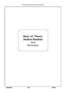
CLOSED CENTER CONVERSION OPEN CENTER PASSAGE CONVERTS TO CLOSED CENTER
CLOSED CENTER PLUG END OUTLET
RETURN PASSAGE
This option provides for conversion from open center to closed center by blocking the open center flow passage with the closed center plug as shown. It may be used in any standard CROSS SA or BA valve featuring the conversion plug/power beyond machining in the BYD port. The valve may also be ordered already converted to closed center. (See table) These valves have less clearance between the spool and body so leakage between the spool and valve body which may result in creeping of the cylinder is minimized.
To convert an open center valve, remove the short conversion plug SA2 1V2572 1R0035 and replace it with the closed cenSA22 ter plug as shown. The relief on SAF2 the handle end of the valve must be SBA2, SBA2-ORB 1V0206 1R0035 SBA2-CC, SBA2-CC - ORB replaced with a no relief plug. ((See SBA22, SBA22-ORB CONTAINED IN 1V2015 KIT SBA22-CC, SBA22-CC - ORB table for part numbers.) Failure to SBA222, SBA222-ORB SBA222-CC, SBA222-CC - ORB replace the relief will result in SBAF2, SBAF2-ORB SBAF2-CC, SBAF2-CC - ORB chattering caused by the constant SBAF22, SBAF222-ORB SBAF22-CC, SBAF22-CC - ORB bypass of oil and will build excessive heat in the system. An outlet must be plumbed to the tank to dump the oil from the return passage. OPEN CENTER VALVE
CLOSED CENTER PLUG
NO RELIEF PLUG
CLOSED CENTER VALVE
Any restriction in the tank line of a closed center system caused by faulty quick couplers, a collapsed hose, etc. will damage the spool seals, washers and handle bracket (BA only) resulting in external leakage around the spool. Reversing the tractor valve so that the outlet rather than the inlet is pressurized would have the same effect. These possible problems must be remedied within the system. In a closed center system, the neutral pressure sometimes causes leakage between the pressure core and the work ports enabling the cylinders to drift or creep. (Reworking the valve at the factory to a class 1A spool fit will minimize this problem. Valves with class 1A spool fit may be special ordered from
Valves manufactured as closed center do not contain a relief and should never be installed in an open center system or converted to open center due to the possibility of personal injury or system damage!
POWER BEYOND INSTALLATION
USE Power Beyond Sleeve
SLEEVE ASSEMBLY PART #'S BA
SA/AD
1V0208
3/4" NPTF
1V0209
7/8-14 SAE
1V0249
1 1/16-12 SAE
1V2566
7/8-14 SAE
INLET From Tractor Hydraulics or Pump
POWER BEYOND
High Pressure Oil Available for Downstream Function
OUTLET Low Pressure Return Line to Reservoir 19
20
21
22
TROUBLE SHOOTING TIPS FINDING AND SOLVING PROBLEMS: Please read and observe the HYDRAULIC PRODUCT SAFETY SHEET before proceeding further. Your safety is important to us! Gradual or sudden loss of pressure or flow resulting in a loss of power is common in hydraulic system failure. Any one of the system’s components may be at fault. These step-by-step procedures should help you locate and remedy the problem quickly. 1. SYSTEM INOPERATIVE • No oil in system, insufficient oil in system. Fill system. Check for leaks. • Wrong oil in system. Refer to specifications. Change oil. • Filter dirty or clogged. Drain oil and replace filter or filter element. • Oil line restriction. Oil lines dirty or collapsed. Clean or replace. • Air leaks in pump suction line. Repair or replace as necessary. • Worn or dirty pump. Clean, repair or replace. Check alignment. Check for contaminated oil. Drain and flush system. • Badly worn components (valves, cylinders, etc.) Examine and test for internal or external leakage. Replace faulty components. Check for cause of wear. • Leakage. Check all components, particularly the relief valve for proper settings. Refer to technical manuals. • Excessive load. Check unit specifications for load limits. • Slipping or broken pump drive. Repair or replace belts, couplings, etc. Check for proper alignment or tension. 2. SYSTEM OPERATES ERRATICALLY • Air in system. Check suction side of system for leaks. Repair. • Cold oil. Allow ample warm-up period. • Dirty or damaged components. Clear or repair as necessary. • Restrictions in filters or lines. Clean and/or replace elements or lines. 3. SYSTEM OPERATES SLOWLY • Oil viscosity too high, cold oil. Allow oil to warm up before operating machine. • Low pump drive speed. Increase engine speed (check manual for recommendations.) • Air in system. Check suction side for leaks. Repair. • Badly worn pump, valves, cylinders, etc. Repair or replace as needed. • Restrictions in filters or lines. Clean and/or replace elements or lines. • Improper adjustments. Check orifices, relief valves, etc. Adjust per manual. • Oil leaks. Tighten fittings. Replace seals or damaged lines. 4. SYSTEM OPERATES TOO FAST • Wrong size or incorrectly adjusted restrictor. Replace or adjust as necessary. • Engine running too fast. Reduce engine speed. 5. OVERHEATING OF OIL IN SYSTEM. • Oil passing thru relief valve for excessive time. Return control valve to neutral when not in use. • Incorrect oil, low oil, dirty oil. Use recommended oil, fill reservoir, clean oil, replace filter elements. • Engine running too fast. Reduce engine speed. • Excessive component internal leakage. Repair or replace component as necessary. • Restriction in filters or lines. Clean and/or replace elements or lines. • Malfunctioning oil cooler. Clean or repair.
5. OVERHEATING OF OIL IN SYSTEM. (cont’d.) • Insufficient heat radiation. Clean dirt and mud from reservoir and components. • Malfunctioning component. Repair or replace. • Reservoir too small. Recommended size is 1 1/2 times pump gpm. 6. FOAMING OF OIL • Incorrect, low or dirty oil. Replace, clean or add oil as needed. • Air leaks. Check suction line and component seals for suction leaks. Replace. 7. NOISY PUMP • Low oil level, incorrect oil, foamy oil. Replace, clean or add oil as needed. • Suction line plugged or too small, inlet screen plugged. Clean or replace. Follow instructions packed with unit. • Use of pipe fitting in inlet. Replace with correct fitting. 8. BLOWN SHAFT SEAL • Pump: wrong pump shaft rotation. Replace seal. Refer to installation instructions. • Motor: failure to hook up drain line. Replace seal. Refer to installation instructions. 9. LEAKY PUMP OR MOTOR • Damaged or worn shaft seal. Replace seal. Check for misalignment. • Loose or broken parts. Tighten or replace. 10. LOAD DROPS WITH CONTROL VALVE IN NEUTRAL • Leaking cylinder seals or fittings. Replace worn parts. • Control valve not centering when released. Check linkage. Check for spool binding. Repair. 11. CONTROL VALVE DOES NOT CENTER (Binding) • See Hydraulic Product Safety sheet. • Valve linkage misaligned. Repair. • Tie-bolts too tight (stack valves). Loosen as necessary. • Valve damaged. Repair or replace. • Handle bracket screws loose. Tighten. 12. CONTROL VALVE LEAKS EXTERNALLY • Tie-bolts too loose (stack valves). Tighten as necessary. • Seals damaged or worn. Replace. • Back pressure or restriction in tank line. Check quick couplers. Use power beyond when necessary. • Cracked port or body. Replace. (see Hyd. Prod. Safety) 13. CYLINDER LEAKS EXTERNALLY • Seals damaged or worn. Replace. • Rod damaged. Replace. 14. CYLINDER LOWERS WITH VALVE IN “METER UP” POSITION • Damaged or leaky load check. Replace check. • Leaking cylinder seal. Replace seal. • Use of a valve without loadcheck. Replace with recommended valve.
23