2012 Asia-Pacific International Symposium on Aerospace Technology Nov. 13-15, Jeju, Korea
Automatic Aircraft Collision Avoidance Algorithm Design for Fighter Aircraft Russell Turner1, Richard Lehmann1, Jason Wadley1, Daniel Kidd1, Donald Swihart2, James Bier2, Kerianne Hobbs2 1
Lockheed Martin Aeronautics Company, Fort Worth, TX, USA 2 Air Force Research Laboratory, WPAFB, OH, US
----------------------------------------------------------------------------------------------------------------------------------------------------------------------------------------------------------------------------------------------------------------------------------------------
Abstract The U.S. Department of Defense has identified midair mishaps as a leading cause of loss of life, lost combat capability, and financial cost in fighter/attack aircraft operations. In the past, losses from midair mishaps were mitigated through training and ineffective warning systems. Now, an Automatic Air Collision Avoidance System (Auto ACAS) has been identified as a technology that could significantly reduce midair accidents. The Air Force Research Laboratory (AFRL) and Lockheed Martin are developing Auto ACAS for fighter aircraft operating in an air combat training environment. In this environment, emphasis is placed on providing protection for aircraft performing air combat maneuvers while eliminating nuisance. Auto ACAS is not a pilot advisory system or a de-confliction system; rather, Auto ACAS performs an automatic, aggressive maneuver to avoid collisions with other aircraft and returns control to the pilot as soon as the collision is prevented. The system coordinates maneuver trajectories between aircraft, determines which combination of maneuvers provides the best separation, and initiates maneuvers when a collision is imminent. The maneuvers incorporate pilot preferences and rules of the road where applicable and possible. Most maneuvers last only two to three seconds and occur well within the reaction time of an alert pilot. Keywords: Auto ACAS, Collision Avoidance, Autopilot, Air Combat Training Collision Protection ----------------------------------------------------------------------------------------------------------------------------------------------------------------------------------------------------------------------------------------------------------------------------------------------
less than 500 feet. However, Auto ACAS must trigger soon enough that the aircraft do not “trade paint.” Auto ACAS system errors, uncertainties and aircraft physical size mean that the actual Auto ACAS trigger should happen early enough to account for these distances.
1. Introduction The Secretary of Defense established the goal of realizing a 75% reduction in Department of Defense mishaps. Examination of historical records revealed that midair, Controlled Flight Into Terrain (CFIT), Gravityinduced Loss of Consciousness (G-LOC), target fixation, and spatial disorientation related mishaps were responsible for more than half of the fighter mishaps. Further research found that the traditional mitigation efforts of training and manual ground collision avoidance systems were not sufficient. A collision avoidance system was necessary to take brief control of the aircraft to fly it out of danger and substantially reduce the fighter aircraft mishap rates. Based on these findings, the Office of the Secretary of Defense (OSD) provided the seed money to the Air Force Research Laboratory to create the Automatic Collision Avoidance Technology/Fighter Risk Reduction Program (ACAT/FRRP). The specific requirement for ACAT/FRRP is to develop an automatic air collision avoidance system that could easily be deployed to protect aircraft in the highly dynamic fighter training environment during air combat maneuvering (ACM). Typical training rules do not allow the aircraft to fly within 500 feet of each other during ACM. This means that to ensure nuisance free operation, the Auto ACAS should trigger late enough to allow the aggressive automatic maneuver to induce a minimum miss distance of
2. Algorithm Goals and Constraints The primary purpose of the system is to prevent mid-air collisions of cooperating fighter aircraft during combat training exercises. Auto ACAS is to determine when a mid-air collision is imminent and to perform an automatic avoidance when necessary. High level requirements in order of priority are 1) do no harm, 2) do not interfere, and 3) prevent collisions. This design philosophy is based on experience and the pragmatic realization that it is better to provide partial protection that pilots will accept and use than to design a system for 100% protection that pilots will reject because it interferes with their normal flight activities. Auto ACAS is to provide protection over the portions of the flight envelope most relevant to combat training exercises and historical mishaps for gear up operation and for store loadings representative of air combat training missions. Historical mishaps for the USAF indicate the majority of mid-air collision mishaps occur during training. Therefore, Auto ACAS would not be required for operational missions. The “do no harm” requirement identifies that Auto ACAS operations cannot result in 1
Copyright 2012 Lockheed Martin Corporation
Form Approved OMB No. 0704-0188
Report Documentation Page
Public reporting burden for the collection of information is estimated to average 1 hour per response, including the time for reviewing instructions, searching existing data sources, gathering and maintaining the data needed, and completing and reviewing the collection of information. Send comments regarding this burden estimate or any other aspect of this collection of information, including suggestions for reducing this burden, to Washington Headquarters Services, Directorate for Information Operations and Reports, 1215 Jefferson Davis Highway, Suite 1204, Arlington VA 22202-4302. Respondents should be aware that notwithstanding any other provision of law, no person shall be subject to a penalty for failing to comply with a collection of information if it does not display a currently valid OMB control number.
1. REPORT DATE
2. REPORT TYPE
NOV 2012
N/A
3. DATES COVERED
-
4. TITLE AND SUBTITLE
5a. CONTRACT NUMBER
Automatic Aircraft Collision Avoidance Algorithm Design for Fighter Aircraft
5b. GRANT NUMBER 5c. PROGRAM ELEMENT NUMBER
6. AUTHOR(S)
5d. PROJECT NUMBER 5e. TASK NUMBER 5f. WORK UNIT NUMBER
7. PERFORMING ORGANIZATION NAME(S) AND ADDRESS(ES)
8. PERFORMING ORGANIZATION REPORT NUMBER
Lockheed Martin Aeronautics Company, Fort Worth, TX, USA 9. SPONSORING/MONITORING AGENCY NAME(S) AND ADDRESS(ES)
10. SPONSOR/MONITOR’S ACRONYM(S) 11. SPONSOR/MONITOR’S REPORT NUMBER(S)
12. DISTRIBUTION/AVAILABILITY STATEMENT
Approved for public release, distribution unlimited 13. SUPPLEMENTARY NOTES
See also ADA578411. Asia-Pacific International Symposium on Aerospace Technology (APISAT 2012) Held in Jeju, South Korea on November 13-15, 2012. AOARD-CSP-131003 14. ABSTRACT
The U.S. Department of Defense has identified midair mishaps as a leading cause of loss of life, lost combat capability, and financial cost in fighter/attack aircraft operations. In the past, losses from midair mishaps were mitigated through training and ineffective warning systems. Now, an Automatic Air Collision Avoidance System (Auto ACAS) has been identified as a technology that could significantly reduce midair accidents. The Air Force Research Laboratory (AFRL) and Lockheed Martin are developing Auto ACAS for fighter aircraft operating in an air combat training environment. In this environment, emphasis is placed on providing protection for aircraft performing air combat maneuvers while eliminating nuisance. Auto ACAS is not a pilot advisory system or a de-confliction system; rather, Auto ACAS performs an automatic, aggressive maneuver to avoid collisions with other aircraft and returns control to the pilot as soon as the collision is prevented. The system coordinates maneuver trajectories between aircraft, determines which combination of maneuvers provides the best separation, and initiates maneuvers when a collision is imminent. The maneuvers incorporate pilot preferences and rules of the road where applicable and possible. Most maneuvers last only two to three seconds and occur well within the reaction time of an alert pilot. 15. SUBJECT TERMS 16. SECURITY CLASSIFICATION OF: a. REPORT
b. ABSTRACT
c. THIS PAGE
unclassified
unclassified
unclassified
17. LIMITATION OF ABSTRACT
18. NUMBER OF PAGES
SAR
7
19a. NAME OF RESPONSIBLE PERSON
Standard Form 298 (Rev. 8-98) Prescribed by ANSI Std Z39-18
2012 Asia-Pacific International Symposium on Aerospace Technology Nov. 13-15, Jeju, Korea
damaging the aircraft. The “do not interfere” requirement identifies that Auto ACAS operations cannot get in the way of the pilot completing the current operational mission. The “prevent collisions” requirement identifies that the Auto ACAS operations will automatically take control of the aircraft and perform an avoidance maneuver to prevent a mid-air collision with another aircraft. For the Auto ACAS algorithms to initiate a request to perform an avoidance maneuver, a significant set of data is required on the ownship aircraft as well as threat aircraft. Current state and position data of the aircraft are required so that the starting locations of the aircraft are known. The Auto ACAS algorithms then generate trajectory predictions based on selected maneuvers available for the avoidance maneuver. Collision estimation is accomplished, and the avoidance maneuver is selected, based on the geometry of the encounter. Algorithm prediction data has to be shared between the aircraft so that each aircraft understands the avoidance maneuvers the algorithm is requesting for each threat aircraft. Another important data parameter is a time measurement which allows aircraft to correlate and align the data received from other aircraft. The algorithm is designed to handle data from cooperating threat aircraft (aircraft that share Auto ACAS algorithm data via a datalink source and can perform an automatic avoidance) as well as noncooperating threat aircraft (aircraft that do not have Auto ACAS algorithms but the ownship aircraft does receive state and position information from a radar or datalink source). For Auto ACAS algorithms, data has to be shared between aircraft. Therefore, to accomplish transfer of data between aircraft, a datalink function has to be available on the aircraft. A cost effective approach is to utilize an existing datalink already present on the aircraft or on a pod platform that is configured for installation on the aircraft carriage. For the F-16 aircraft, the Aircraft Combat Maneuvering Instrumentation (ACMI) pod is utilized for combat training and includes a datalink that Auto ACAS can utilize. Nuisance considerations are another element that has to be included in the Auto ACAS algorithm design. The purpose of the training exercises is for the pilot to gain proficiency in air combat maneuvering skills. A large part of this exercise is to allow aircraft the ability to get close to each other in the air so that they can train appropriately. Therefore, Auto ACAS cannot request activations such that they become a nuisance to the pilot by interfering with the training exercise. The Auto ACAS algorithms are designed to only request an avoidance maneuver when a collision is imminent and it is too late for the pilot to react and avoid the collision.
3. Algorithm History An early version of Auto ACAS was developed through a cooperative program between the United States and Sweden that began development in 2001 and concluded with a 2003 flight test demonstration. The flight testing encompassed the use of a virtual target aircraft, a real F-16 target aircraft, and a simulated unmanned air vehicle (UAV) target aircraft as the second vehicle in the collision test scenarios. A virtual target aircraft is a ground-based computer that simulates a flying aircraft and provides the appropriate Auto ACAS data to a datalink. Based on the position data received over the datalink from a real aircraft in the air, the simulated aircraft is placed nearby and in the desired geometry to execute a flight test run. The purpose of this initial Auto ACAS program was to establish a proof-of-concept midair collision avoidance system that did not interfere with normal fighter aircraft operations. The architecture consisted of a subsystem that hosted the algorithms and received threat aircraft from a datalink system on the aircraft and to a limited extent radar track information. The subsystem hosting the algorithms communicated with the digital flight controls when to execute an automatic avoidance maneuver. If proximity criteria were met within the collision prediction, an automatic avoidance maneuver was executed. Internal monitoring was developed to maintain the integrity and safe operation of the system [1]. Based on this initial limited flight test and simulation evaluation, Auto ACAS demonstrated a robust architecture that consistently prevented midair collisions under complex conditions, albeit with only satisfactory results [1-3]. Although the concept of using an airborne datalink to provide aircraft trajectory information was found to be acceptable, some problems were experienced with datalink failures [1, 2]. The avoidance maneuvers employed by the system were not always acceptable to the pilot and the system could not handle very dynamic changes with the collision geometry. The basic collision avoidance objective of the program was satisfied, and this initial Auto ACAS development and flight test demonstration provided a significant step in the development of the technology. The discussion that follows identify the next steps that are being taken to mature the technology further.
4. Algorithm Description The Auto ACAS algorithms represent a critical system component which determines when an automatic maneuver is required to avoid a mid-air collision. The algorithms provide the following capabilities: 1) receive threat and ownship data from aircraft systems, sensors (radar), and datalinks; 2) accommodate cooperating and noncooperating threats; 3) generate an ownship trajectory for the selected avoidance maneuver; 4) generate alternate 2
Copyright 2012 Lockheed Martin Corporation
2012 Asia-Pacific International Symposium on Aerospace Technology Nov. 13-15, Jeju, Korea
ownship trajectories that may be performed; 5) compare the ownship trajectories to other aircraft trajectories and determine if a maneuver should be requested or deactivated; 6) coordinate maneuvers with other aircraft; and 7) accommodate failures, formation flight, and other flight modes. From a high-level perspective, the algorithm architecture which provides these capabilities is shown in Figure 1. Integrity Management
Aircraft State
Integrity Management
Aircraft Recovery Trajectory Prediction
Predicted Trajectory
Notify Pilot
Data Type
Collision Estimation Recovery Request
Navigation Solution
Trajectory Prediction Model Normal Trajectory predicted by Velocity extrapolating along velocity vector Velocity Very Low Threat is considered Only Velocity uncontrolled; Trajectory predicted using a ballistic model Low-G Trajectory predicted using a Loading kinematic model Velocity and High-G Trajectory predicted using a Acceleration Loading constant radius turn about a center point model Auto ACAS and ACMI datalink messages are tagged with an aircraft identification number that is used to differentiate between threats. Radar/unspecified threats are not identified and a decision must be made whether the input radar/unspecified threats represent known threats (threats already tracked by the system) or new threats. In order to do this, a correlation process is used to eliminate duplicate threat messages. Throughout the correlation and assignment process, the most recent data from the highest priority data source is used. The data source priority is defined as follows: 1) Cooperating Auto ACAS Threats; 2) Non-cooperating ACMI Threats; and 3) Non-cooperating Radar/Unspecified Threats.
Command Recovery
Track File & Conflict Determination
Radar Target Location 3-D Intersection Profile
ACMI Pod Aircraft Location And Intent
that threat. For instance, ACMI threat messages do not contain acceleration data so the trajectory is predicted using velocity data only. Threats containing acceleration data are handled differently depending on the magnitude of that acceleration. The different trajectory prediction methods are described in Table 1. All predicted trajectories have an inherent increase in uncertainty due to unknown pilot intent, and the algorithms account for this uncertainty when determining to activate an automated maneuver. Table 1. Trajectory Prediction Models
Cooperating & Non-Cooperating Aircraft Data
Contains: Maneuver Selection and Coordination Maneuver Activation and Control
Contains: Track Manager Threat Isolation Formation Logic
Fig. 1 Algorithm Architecture Because Figure 1 is a summary figure and does not show every detail of the algorithm design, the following elements of the Auto ACAS algorithms are discussed further: 1) Track Manager; 2) Threat Isolation; 3) Formation Logic; 4) Trajectory Prediction; 5) Maneuver Selection and Coordination; and 6) Maneuver Activation and Control. 4.1 Track Manager The element of the algorithm responsible for receiving and organizing incoming threat information is referred to as the Track Manager. The Track Manager receives threat information from multiple sources, determines the best estimate of the actual number of threats, assembles their current trajectories, and organizes the incoming information into a single output threat data structure. The incoming information sources can be divided into two main categories: 1) Cooperating threats which communicate via the Auto ACAS datalink message; and 2) Non-Cooperating threats which come from non-Auto ACAS specific sources (such as the ACMI Pod message, ownship radar, and other/unspecified sources). All threats are propagated to the current ownship time to position the threats in a common reference frame for threat correlation and collision detection. Threat messages older than a staleness threshold are considered unreliable and are thrown out due to staleness. Cooperating threats are propagated along the trajectory received from the Auto ACAS datalink message. Non-Cooperating threats do not provide a trajectory so the Track Manager must predict a trajectory for these tracks. The Track Manager has multiple paths for predicting threat trajectories depending on what data is available for
4.2 Threat Isolation Threat Isolation reduces the full threat list determined by the Track Manager to a shorter list of the most imminent threats. The algorithm scores each of the threats to determine the three threats that pose the greatest risk to the ownship aircraft. The score (J) is determined by a weighted combination of the slant range (R) and range rate (Rdot) as shown in equation [1] below:
J
Vcrit Rdot ; R
1 R; Rdot 0;
(1)
Weighting factor (Vcrit) is an adjustable constant used to place a higher priority on either range or range rate to achieve optimal threat risk evaluation. When the range rate 3
Copyright 2012 Lockheed Martin Corporation
Conditions
2012 Asia-Pacific International Symposium on Aerospace Technology Nov. 13-15, Jeju, Korea
is positive (aircraft are separating), the range rate term is eliminated from the scoring equation. After scoring, the threats are then sorted based on score and the threats with the three highest scores are selected for processing in the remainder of the algorithm.
than-real-time on a single processor leads to a compromise between accuracy and speed of computation. The design is essentially a well-behaved multi-dimensional curve-fit that is loosely based on a simplification of a 6-DOF aircraft model. Some consideration was given to generating a multi-dimensional curve-fit using neural network or other generic curve-fitting techniques, but it was thought that a 6DOF type framework with the addition of table-driven aircraft response modules (i.e., a combination of 1 st- and 2nd- order models) would be easier to understand, easier to design, and easier to ensure stable behavior. The TPA design has also been partitioned into generic and aircraftspecific sections in order to maximize reuse of code and to simplify integration of new aircraft types into Auto ACAS. Using MatLab optimization toolboxes, a tuning tool was developed to automatically adjust the model coefficient tables in order to get the best performance possible from the simplified models. First, a “Truth” data set is generated by running a high fidelity off-line performance model of the aircraft to generate reference trajectories for many different flight conditions and maneuver selections. The tuning tool reads in this truth data and then runs the TPA to generate estimated trajectories at these same set of flight conditions. The tuning tool tabulates the errors between the truth data and the TPA data. The tool then adjusts the coefficients in the tables and reruns the TPA to generate a new set of TPA data. The tool keeps changes that improve the overall TPA accuracy and rejects changes that tend to worsen TPA accuracy. Although the tool is automated, the algorithm developer must review the results and help guide the tuning tool to try to achieve the best performance. In addition to the trajectory prediction, an estimate of the TPA’s accuracy at any particular condition must be provided in order to allow the algorithms to account for uncertainties/errors introduced into the Auto ACAS by the TPA.
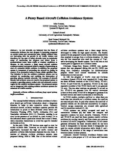
4.3 Formation Logic Formation logic determines if the ownship aircraft is in close fingertip formation flight with any detected threat aircraft and sets a bit to inhibit Auto ACAS activations while in formation flight. The formation strategy builds a region around the aircraft defined by range and closure rate to allow uninterrupted formation. The formation boundary conditions are defined in Figure 2. This strategy was developed based upon previous testing conducted by AFRL [4].
Fig. 2 Formation Boundary Diagram Threat aircraft are considered to be in formation when one of the following conditions is satisfied: 1) Range is inside the Formation Deactivation Zone (FDZ); or 2) Range and closure rate fall within the System Standby Region. A 20% buffer is added to the closure rate boundary and FDZ range boundary while the aircraft are in those regions to prevent formation exiting from small fluctuations near the formation boundary. Similarly, the maximum formation range is increased by 25ft when aircraft are in the System Standby Region. Aircraft remain in formation until their range or closure rate exceed these relaxed boundary conditions.
4.5 Maneuver Selection and Coordination Within the algorithms, each cooperating aircraft must generate up to three avoidance trajectories that may be performed. These three avoidance trajectories are chosen from a pool of nine available maneuvers representing three different maneuver types. The first maneuver type is called a roll-and-pull maneuver because Auto ACAS commands a bank angle for the aircraft while pulling a 5g maneuver. Seven of the available nine maneuvers are roll-and-pull maneuvers with the bank command chosen as an incremental change from the current aircraft bank angle at the discrete commands of -90 deg, -60 deg, -30 deg, 0 deg, 30 deg, 60 deg, and 90 deg. These relative bank commands are limited to the range of +/- 90 deg to minimize the amount of time the aircraft is rolling without
4.4 Trajectory Prediction The Trajectory Prediction Algorithm (TPA) estimates the future path of the aircraft over the next 4.5 seconds for an automated maneuver. This prediction is based on current aircraft states and the selected Auto ACAS maneuver. The TPA is called multiple times each frame in order to model different potential maneuvers. Section 4.5 defines the maneuvers the TPA provides. The requirement to model multiple trajectories at faster4 Copyright 2012 Lockheed Martin Corporation
2012 Asia-Pacific International Symposium on Aerospace Technology Nov. 13-15, Jeju, Korea
performing a maneuver. The second maneuver type is a bunt maneuver in which the bank angle is held constant while the flight controls perform a -0.5 g push on the aircraft. The third maneuver type is called a maintain maneuver because both the bank angle and g-loading are held constant while the aircraft continues the pilot maneuver performed at the moment of activation. Although nine maneuvers are available, at any instant of time the Auto ACAS algorithms only choose three maneuvers for consideration. The algorithms choose the best maneuver identified in previous processing frames as the first maneuver for the current maneuver selection. This best maneuver will continue to be the first choice until another maneuver is clearly identified as superior. The algorithms also choose two alternate maneuvers for consideration. Auto ACAS uses a pre-selection process to evaluate the nine available maneuvers to determine which maneuvers are appropriate given the current flight state and geometry of the engagement. Pre-selecting the maneuvers ensures that computational time is not used for maneuvers that can be eliminated through offline analysis, and the preselection logic is a key element in achieving pilot acceptance of the maneuvers. This pre-selection process incorporates rules of the road, pilot training and preferences, collision geometry, and maneuver effectiveness and energy considerations when determining which of the nine maneuvers are appropriate at the current instant of time. From this evaluation, the algorithms create a subset of the available maneuvers for further processing. For example, if the two aircraft are in a nearly head-on collision, the algorithms will eliminate the options for banking left and will retain only the maneuvers which include a bank to the right so that both aircraft will avoid with the other aircraft to the left. Therefore, only four maneuvers may be considered for this scenario with the algorithm sequencing between the four maneuvers systematically to choose only two alternate maneuvers at any instant of time. With the maneuver commands identified, the algorithms proceed to generate and share the trajectories. Like the primary trajectory, the algorithms generate trajectories for the alternate maneuvers using the TPA, as previously described. Because of bandwidth limitations, the datalink can not transmit every point in the trajectory. Consequently, the datalink broadcasts a total of four threedimensional positions from the trajectory along with initial and final velocities. Other aircraft receiving this data then reconstruct the trajectory using cubic spline interpolation. Once all of the aircraft trajectories have been shared among the participants, the algorithms must agree on which set of maneuvers provides the best solution. To accomplish this, the Auto ACAS algorithms utilize a cost function based on the predicted minimum avoidance distance (AD) between pairs of trajectories of the aircraft.
Uncertainty estimates are included when calculating the predicted avoidance distances. Mathematically, the cost function is shown in equation [2]. (2) The selection algorithm systematically generates a score of all possible maneuver combinations, compares each cost, and selects the first combination which provides the lowest cost. Figure 3 shows a graphical representation of this process for a scenario involving four aircraft. On the left side of this figure is one particular combination of maneuvers while on the right side is a second representation after a new maneuver for the third aircraft is considered. The algorithms repeat this process to evaluate all the combinations. For four aircraft, the algorithm may need to consider up to 81 combinations of maneuvers. It should be noted that each aircraft is independently scoring the maneuvers and selecting the best combination to be performed; therefore, the algorithms cross check the final solution to ensure no conflicts exist before an avoidance maneuver can be performed. Aircraft 4
Aircraft 3
Aircraft 3
Combination 1 (Aircraft 3 Maneuver 1)
Aircraft 1
Aircraft 2
Combination 2 (Aircraft 3 Maneuver 2)
Aircraft 1
Aircraft 2
Fig. 3 Maneuver Selection Scoring One of the technical challenges for Auto ACAS is achieving sufficient trajectory coordination between the cooperating aircraft. Because Auto ACAS is designed to operate in an air combat training environment that is highly dynamic, the algorithms need to choose candidate maneuvers, share the resulting trajectories, and determine if any new combination of maneuvers is better than the currently selected combination in a short amount of time. However, because a finite amount of time is required to share information between aircraft and because data dropouts are possible, the maneuvers will become uncoordinated if the algorithm attempts the process too rapidly. For instance, if the algorithm attempts to make a scoring comparison and decision every processing frame, the transmission delays in sharing the information will cause the system to get out of phase and possibly result in uncoordinated trajectories. To address this challenge, the algorithms purposefully introduce damping into the solution to achieve coordination. Rather than choosing new combinations of maneuvers for 5
Copyright 2012 Lockheed Martin Corporation
Aircraft 4
2012 Asia-Pacific International Symposium on Aerospace Technology Nov. 13-15, Jeju, Korea
each frame of operation, the algorithms only select maneuvers periodically. For the periodically selected frame, maneuvers are compared, and a new maneuver may be selected as the best maneuver. During the other frames that a selection is not made, the three maneuver commands do not change, but the maneuver trajectories are updated to account for changing flight states. These updated maneuvers are also broadcast via the datalink to share the latest information. However, the scoring and final decision for maneuver combinations occur in the periodically selected frame. Once the decision has occurred, new candidate maneuver trajectories are computed and shared so that the information is ready at the time of the next decision.
avoid if necessary. The algorithms then monitor the trajectories of the aircraft which caused the maneuver activation and ensure that they are sufficiently separating before maneuver deactivation can occur. The algorithms monitor the range rate only amongst the affected aircraft as part of this process. If the maneuver is still active after 4.5 seconds, the algorithm will timeout and deactivate the maneuver.
5. Testing Approach The current project plan is to conduct flight testing of the system in early 2014. Because of the hazardous nature of the testing and the difficulty of setting up highly dynamic ACM test scenarios in a safe manner, a build up approach to testing has been developed. The first phase of testing is to perform extensive evaluation of the Auto ACAS using high fidelity simulators. An Auto ACAS simulation facility has been designed that has six high fidelity aircraft simulators integrated with Auto ACAS. Two of the simulators have cockpits and wide field-of-view (FOV) dome simulators. Figure 5 illustrates one of these simulators. The other four simulators are workstations with joysticks, throttles and 6monitor displays. Any of the simulators can be run as either scripted simulations or as pilot-in-the-loop simulations. The wide field-of-view dome simulators were required to allow pilots to see the other aircraft while performing air combat maneuvering and formation flying. Scripting tools were developed that enable repeatable testing of highly dynamic flight conditions and collision geometries. The simulators are used to evaluate the Auto ACAS design over the aircraft flight envelope and at collision scenarios that are too dangerous to test in flight test.
4.6 Maneuver Activation and Control Throughout the engagement, the algorithms monitor the best avoidance trajectory from each aircraft to determine if an avoidance maneuver is required. Although maneuver coordination involves scoring of all combinations of trajectories, only the best avoidance trajectory is needed to determine if an avoidance maneuver should be activated or deactivated. Using the best trajectory for each aircraft and including uncertainties around that trajectory, a cone representing the volume of space the aircraft may fly through is determined. As the risk of collision becomes more likely, the cones of two aircraft will converge in time and space (i.e., four dimensions). At the moment that the two cones “touch” one another, the algorithm initiates the request to perform the identified avoidance maneuvers (see Figure 4).
Fig. 5 Auto ACAS Dome Simulator Flight testing will involve two methods of testing. The first method is to use an active Auto ACAS in a series of controlled, defined runs that will allow the Auto ACAS to perform automated avoidance maneuvers. This testing will be conducted in two configurations in which one aircraft flies against a virtual aircraft or in which two physical aircraft fly against each other. This testing will try to duplicate runs that have been performed in the simulators so that the results generated in the simulators can be validated to represent the actual aircraft performance. Once the simulator data is validated, then there is confidence that the simulators give an accurate
Fig. 4 Trajectory Cones Because the Auto ACAS on each aircraft independently chooses the best maneuver, the algorithms utilize a safety mechanism as a final check to ensure a bad combination of maneuvers is prohibited. This safety mechanism monitors the trajectory cones and determines if they are penetrating one another in time and space rather than simply touching. When penetrating, the algorithm will not request an avoidance maneuver. Once an activation occurs, the algorithms continue to transmit the avoidance trajectory so that other aircraft can 6 Copyright 2012 Lockheed Martin Corporation
2012 Asia-Pacific International Symposium on Aerospace Technology Nov. 13-15, Jeju, Korea
representation of how Auto ACAS performs in conditions that are harder to test safely in flight test. Additional flight test software features are being made available to allow nuisance evaluation of Auto ACAS during ACM training operations. This test software function, when activated, allows the Auto ACAS algorithms to continue to operate and generate output results, but prevents the digital flight controls from responding to a request for an automatic avoidance maneuver. This allows the pilot to fly normal ACM training profiles and collect data on whether the system would have triggered any inappropriate automated maneuvers that would interfere with the pilot performing his normal flying duties. This allows the collection of Auto ACAS performance data during highly dynamic maneuvering without the risk of initiating an automatic maneuver at an inappropriate time. This is critical when developing the flight test safety plan.
Acknowledgement None.
References [1] Jones, S., Panagos, J., Lehmann, R., Davis, H., et al., “F-16 Automatic Air Collision Avoidance System Final Report,” Lockheed Martin Aeronautics Company, 721PR403, 2003. [2] Skoog, M., Less, J., and Chen, J., “Automatic Air Collision Avoidance System (Auto ACAS) Initial Flight Test Evaluation Final Report,” AFFTC-TR-04-04, 2005. [3] Jones, S., Lehmann, R., Lewis III, C., Panagos, J., et al., “ACAS Algorithm Follow-On Study Report,” Lockheed Martin Aeronautics Company, 2004. [4] Baker, Michael, et al, “Nuisance Criteria Data Gathering For Automatic Air Collision Avoidance System and Testing of a Low Cost Aircraft Reporting System, Project “Have Grape,” AFFTC-TIM-02-04, Edwards AFB, CA, 2002
6. Conclusions The U.S. Department of Defense has identified midair mishaps as a leading cause of loss of life, lost combat capability, and financial cost in fighter/attack aircraft operations. Initial Auto ACAS development and flight demonstration in 2003 provided a ray of hope that the system could be an enabler for reducing mid-air mishaps. Further steps in the maturity of the algorithms in the current program have been taken to meet the expansion and more stringent requirements of non-interference to mission operations during highly dynamic ACM training operations. A heavy reliance on simulation testing is justified as building blocks for safely conducting flight test in the air combat environment. Initial testing of the algorithms described above have provided encouraging results that the Auto ACAS being developed can meet the requirements. However, the impacts of the datalink performance in a flight environment to Auto ACAS operation still needs to be evaluated before this system can be further matured and prepared for operational use. In addition, the Automatic Ground Collision Avoidance System (Auto GCAS) which has been previously developed by this group and is in the process of being transitioned to production fighter platforms must be integrated with Auto ACAS operation in the future. Once Auto ACAS operation can be realized in the current development and flight test demonstration, the further development of integrating the technology with Auto GCAS can proceed. Continued efforts with maturing this technology will hopefully result in the transitioning of Auto ACAS to the production fighter platforms and provide additional protection for fighter pilots and aircraft during training operations so that they can be better equipped and still available to defend the nation.
7 Copyright 2012 Lockheed Martin Corporation