ATL Fuel Level Gauge Installation and Calibration Procedure Sending Unit
Aero Tec Laboratories ATL USA: e-Mail:
[email protected] Web: www.atlinc.com Tel: (001) 201-825-1400 Fax: (001) 201-825-1962
Level Meter
ATL Europe: e-Mail:
[email protected] Web: www.atlltd.com Tel: +44 (0) 1908-351700 Fax: +44 (0) 1908-351750 ATL Level Gauge Kit includes:
This “Procedure” Covers:
1 1
Kits: KS-143 KS-144 KS-159 KS-160
1 5 5 5 5 1 1
Level Meter (Gauge) Sending Unit (Probe), Standard Range 240 to 33 ohms Sending Unit Gasket 10-32 x 1.5” or M5 x 38mm Screws 10-32 or M5 Elastic Stop Nuts #10 Seal-Washers #10 Lock-Washers Anti-Chafe Button Installation Procedure Bulletin #DS-448
Meter Only KS-116
Sending Unit Only: KS-146 KS-147 KS-157 KS-158 KS-170 KS-171 KS-172 KS-173
WARNING: Before you work on any fuel bladder, be sure that it has been completely drained of fuel and inerted by rinsing with water. Read ATL Product Safety Bulletin # DS-381 (see page 6). NOTE: ATL’s Level Gauge Kits and Sending Units (probes) are intended for use in ATL Safety Fuel Cells, however they can NOT be used in Racell-Red and Racell-Black fuel cells. Level Gauge installation on TF193, TF193A, and TF525 Fill Plates requires modification of the fill valve for clearance (see pg. 4). SENDING UNIT (PROBE) PREPARATION (See Figure 2 on Pg. 5): Bypass this section if the Sending Unit was installed in your ATL Fuel Cell by the factory. If you have not purchased your Level Gauge system with its Sending Unit installed in an ATL Fuel Cell, it will most likely be necessary to cut the Sending Unit tube to the proper length for your fuel bladder. Measure the depth of your fuel bladder from the outside of the top plate to the inside bottom of the bladder. The Sending Unit is comprised of an encapsulated circuit and two concentric tubes, a larger outer tube and a smaller inner tube. Small plastic insulators separate the two tubes forming a “capacitance probe”. Using a small tubing cutter, cut the outer tube approximately 1/2” to 1” shorter than the measured depth of the bladder. Be careful not to damage the inner tube. Slide at least one of the exposed insulators onto the inner tube until it is just inside the outer tube. Cut off the inner tube so it is flush with the outer tube; a pair of diagonal cutters will work well. After cutting, make sure that the two tubes are not touching. NOTE: The Level Meter will stay pegged above the full mark when power is applied if the two tubes are touching. Any water in the bladder contacting the ends of the Sending Unit probe can also result in a constant full reading. Snap on the anti-chafe button to the end of the Sending Unit probe (see Fig. 2) making sure the inner tube is not touching the anti-chafe button as this will cause a short. SENDING UNIT (PROBE) INSTALLATION (See Pg. 5): Bypass this section if the Sending Unit was installed and calibrated by the ATL factory. ATL’s fuel Sending Unit requires mounting on the fuel cell fill-plate (see Fig. 2 on pg. 5 and the examples on pg. 4). Remove the fill plate from your cell. A template (Fig.1) has been provided on pg. 5 to help in marking the plate for drilling. The 5-bolt pattern is not symmetrical; there is only one correct way to align the holes. After marking the plate for the 5 screw holes and the larger (1.312” dia.) center probe hole, drill the 5 bolt holes (0.2” dia.) as indicated in Fig. 1. 1 DS-448 9/04
Place the supplied gasket between the Sending Unit head and the fill plate (see Fig. 2). Insert the Sending Unit through the hole in the plate and align the bolt holes. NOTE: There is only one correct way to position the Sending Unit and gasket over the holes. Install the supplied bolts and fiber washers and fasten with the lock washers and lock nuts on the underside of the plate. Press the black anti-chafe button onto the end of the sending unit probe. The foam in your fuel cell must be cut away to clear the Sending Unit Probe. A minimum hole size of 1.5” diameter is recommended. Mark the foam with a 1.5” circle and then carefully remove all foam from the fuel cell. Cut the tubular hole with a serrated knife and reinstall the foam (see Fig. 2). Before reinstalling the fill plate, inspect the gasket and sealing washers. Replace any damaged parts. Retorque the fill plate bolts to 40 inch pounds (4.5 Newton-Meters). ELECTRICAL HOOKUP FOR 2-TERMINAL SENDING UNIT (see Figure 2 on pg. 5): WARNING: Always disconnect vehicle battery before attempting any wiring or electrical work. Step 1. Connect a 16 gauge wire from SEND terminal on Sending Unit (Probe) to “S” terminal on Level Meter (Gauge). Step 2. Connect a 16 gauge wire from NEG terminal on Sending Unit to “G” terminal on Level Meter. Then, connect a separate 16 gauge wire from “G” terminal on Level Meter to system “ground” in the electrical system (usually the chassis). Step 3. Connect a 16 gauge wire from “I” terminal on Level Meter to a positive 12 volt point in the electrical system that is switched by ignition switch. Step 4. Reconnect battery and turn on ignition switch. The Level Meter will go to “Full” mark, then drop back to correct fuel level indication. If adjustments on your Sending Unit were altered, or length of Sending Unit tube was shortened, then you must calibrate the system. See “Calibration” below. ELECTRICAL HOOKUP FOR 3-TERMINAL SENDING UNIT (see Figure 3 on pg. 5): WARNING: Always disconnect vehicle battery before attempting any wiring or electrical work. Step 1. Connect a 16 gauge wire from SEND terminal on Sending Unit (Probe) to “S” terminal on Level Meter (Gauge). Step 2. Connect a 16 gauge wire from POS terminal on Sending Unit to “I” terminal on Level Meter. Then, connect a separate 16 gauge wire from same “I” terminal on Level Meter to a positive 12 volt point in the electrical system that is switched by ignition switch. Step 3. Connect a 16 gauge wire from NEG terminal on Sending Unit to “G” terminal on Level Meter. Then, connect a separate 16 gauge wire from “G” terminal on Level Meter to system “ground” in the electrical system (usually the chassis). Step 4. Reconnect battery and turn on ignition switch. The Level Meter will go to “Full” mark, then drop back to correct fuel level indication. If adjustments on your Sending Unit were altered, or length of Sending Unit tube was shortened, then you must calibrate the system. See “Calibration” below. CALIBRATION: WARNING: Gasoline and Diesel are flammable and toxic; exercise extreme caution. In most cases, your Sending Unit and Level Meter will require calibration after installation in your vehicle. Sending Unit must be dry before attempting calibration. Residual liquid left in fuel bladder or tube will affect accuracy of calibration procedure. If the Sending Unit was immersed in fuel, allow it to dry for two hours before calibrating. FULL and EMPTY adjustment screws are located on top of the Sending Unit (diagram at right). A small Phillips screwdriver will be necessary to make adjustments. Make certain that wiring is connected (shown in Fig. 2 or Fig. 3) and fuel bladder is empty. Turn ignition switch on and let system warm up for at least 5 minutes before starting calibration procedure. continued on pg.3
2
Gently turn FULL and EMPTY adjustment screws to full clockwise position. CAUTION: Full travel on screws is only 3/4 turn; avoid excess force that can damage the unit.
With fuel bladder empty, slowly turn EMPTY screw CCW (counter clockwise) until needle on Level Meter just stops moving downward. Needle should be on or just below “Empty” mark.
Turn the same EMPTY screw CW (clockwise), making sure needle starts moving up; then, again turn CCW until needle just stops moving downward. You have now set the EMPTY reference point. Repeat step as many times as necessary, until you are confident the EMPTY reference point has been accurately set. NOTE: Calibrate EMPTY first!
Fill your fuel cell with fuel. Turn FULL screw CCW until needle indicates FULL. If you accidentally turn the screw too far, turn it back to full CW position, then CCW to indicate full bladder level. This completes the calibration procedure; no further adjustments are necessary.
USING STOCK FUEL LEVEL METER (GAUGE): For those wanting to retain the vehicle’s original (OEM) fuel gauge, an ATL Sending Unit can be ordered to match the resistance range. You must supply ATL with the resistance range (full and empty ohm readings) of your OEM gauge, i.e.: ATL = 240 to 33 Ohm, GM = 0 to 90 Ohm, VDO = 70 to 0 Ohm, Toyota/Nissan = 100 to 6 Ohm. TROUBLESHOOTING: The Fuel Level Meter does not move off EMPTY, • Check all wiring. • Check that the ignition is on and that a fuse is not blown. • Ensure there is fuel in the bladder. The Fuel Level Meter indicates FULL all of the time, • Check for water in the tank. • Ensure that the inner tube of the Sending Unit is not touching the outer tube. • Ensure that the Sending Unit is not bent.
3
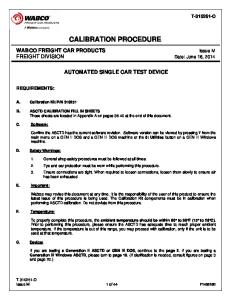
Anti-Chafe Button
Sending Unit (Probe) Level Meter (Gauge)
KS143 Typical Fuel Level Gauge Kit (2-Terminal Shown)
Part#
Length
Ohms MT Ohms Full
KS143
4”-12”
240
33
KS144
12”-24”
240
33
KS159
24”-36”
240
33
KS160
36”-48”
240
33
KS170
4”-12”
0
90
KS171
4”-12”
70
0
KS172
12”-24”
0
90
KS173
12”-24”
70
0
Fill-Plate: TF525 or TF193A -184A Flapper Valve (Trim TF183 or TF184A Valve for fit)
Fill-Plate: TF470 Paddle Valve
Fill-Plate: TF195 or TF600 Flap Valve
Fill-Plate: TF259-OS-TF184A
Typical Sending Unit Installations 4
Product Safety Bulletin IMPORTANT PRECAUTIONS IN USING ATL RACING EQUIPMENT: FUEL CELLS, CHECK VALVES, DUMP CANS, REFUELING RIGS, VENT VALVES, DRY-BREAK COUPLERS, FITTINGS, ETC. PLEASE READ THOROUGHLY AND REFER TO CURRENT ATL COMPETITION EQUIPMENT CATALOG 1. TEMPERATURE – Racing fuel cell bladders rely on deformability to ward off impact and puncture. Decreasing temperatures may limit pliability and could thereby reduce the cell’s effectiveness. Most ATL racing type fuel cells are designed for normal competition environments of 30ºF to 120ºF (0º to 50ºC). Use below -20ºF (-30ºC) may diminish performance. Maximum intermittent bladder exposure temperature is 160ºF(60ºC). 2. LIFE SPAN – Major sanctioning bodies such as FIA, NASCAR, ASA, SCCA, etc. have recognized that fuel cells and related equipment are slowly affected by ozone, ultraviolet, aging and the chemical action of gasoline and racing fuels. Hence, a Five-Year Legal Life Span has been set on all fuel cell bladders. The rubber bladder portion of your fuel cell system must be replaced within 5 years of its manufacture date. No repairs may be made to bladders after that 5-year period has elapsed. Upon factory re-inspection, a 2-year extension may be granted by FIA & SCCA. 3. WATER & MOISTURE – Water vapor and direct sunlight exposure may affect fuel cell bladders and foam baffling. Always install you fuel bladder within a metal or composite enclosure, and keep the system externally and internally free of water and water vapor. 4. DIFFUSION – Due to the polymeric nature of fuel cell bladders, molded tanks and hoses, a certain amount of fuel permeation or “diffusion” will occur through the walls. Always provide generous ventilation around the cell and vehicle so as to preclude the accumulation of hazardous fuel vapors. 5. STORAGE - When storing a fuel cell, drain the bladder completely, wash and dry the interior, close off all ports, and keep it in a dark, warm and dry area (see paragraph #18). 6. WEATHERING EFFECTS – Most racing equipment is affected by weathering; that is: sunlight, wind, freeze-thaw cycles, high and low temperatures, rain and airborne contaminants. Ozone, ultra-violet light, water and acids are especially detrimental to many plastic and rubber parts. Protect your fuel cell and refueling equipment from necessary weather exposure. 7. ABRASION – Many racing products, and especially rubberized fuel cell bladders, are susceptible to chafing or abrasion. Handle these items with care and install them gently without force or compaction. Keep free of pebbles, sand and other abrasives which can wear rubber and plastic materials. Be certain that the tank, container, nacell or cavity which holds a fuel cell bladder is thoroughly smooth and continuous on its interior. Do not put sharp, heavy or irregular loose items (i.e. metal pick-ups, baffles, swirl pots, etc.) inside a fuel cell bladder as they could chafe the rubber and create an eventual leak. 8. FUEL COMPATIBILITY – Most fuel system components are not resistant to all types of fuels. Therefore, it is essential to identify the intended fuel (i.e. gasoline, diesel, methanol, etc.) before purchasing equipment and putting it in service. For example, most fuel cell foam baffling material is adversely affected by alcohol as are certain fuel cell bladders. Other chemical fuels such as nitromethane, nitropropane, hydrazine, and additives such as aniline, toluedine and aromatics can deteriorate hoses, gaskets, valves, bladders and other fuel system parts. Double check compatibility and, when in doubt, contact the ATL factory for advice. Don’t take chances. 9. INSTALLATION – When installing any fuel cell, dry break valve, vent valve, fuel hoses or other ATL components be certain to follow the instructions strictly and carefully. Pay particular attention to location, bracketing, venting, grounding and isolation from the driver compartment. Since every vehicle is different, it is not realistic to prescribe a set method of installation for every ATL product. However, certain basic safety and function practices must be adhered to for all installations. Be certain your installation procedure complies with ATL’s general instructions as well as the specific requirements of your competition organization or sanctioner. When in doubt, consult a professional chassis builder, vehicle engineer or the ATL factory for installation assistance. 10. SAFETY FOAM BAFFLING – Fuel cell foam is a “reticulate” or open-cell sponge-like material. When used within a fuel cell bladder, foam helps suppress explosion, control fuel slosh and absorb some impact energy. Foam should never be handled when wet with fuel as surface fire could erupt. Flush the cell with water before removing foam. Also, SF103 and SF112 foams should be used with gasoline only and not with additives, alcohol or an excess of 40% aromatics. SF110 foam offers the best methanol resistance as well as static charge suppression. Copyright© 2004 Aero Tec Laboratories Inc
6
DS 381
3Q 04
11. INFLATION – ATL tanks and bladders are not to be inflated or pressurized. However, leak testing of these containers with less than 50 gallons capacity may be performed at 1/4 psi (6” water) maximum pressure. An accurate gauge and a redundant pressure regulator system are essential. Overpressurizing may elongate the tank or bladder and damage its seams without visual evidence. 12. CONTAINERS – All fuel cell bladders are to be installed inside a minimum 20 gauge steel or .062” aluminum enclosure (container). These are minimums and thicker walls are sometimes mandatory and always recommended. The container serves to support the bladder, deflect impacts and provide a flame shield. ATL offers ready-made containers as well as drawings and templates for the do-it-yourselfer. When sizing a bladder or container, be sure to leave a clearance for easy installation and removal. Containers for soft rubber bladders (rubberized fabric) should be 1% larger in length, width and height. Containers for molded hard rubber bladders must be 2% larger in each dimension to accommodate linear swell. 13. STATIC GROUNDING – Electrical charges may build up on components due to fuel agitation, high flow rates, and by induction from other sources. To alleviate sparking and possible fuel ignition, always electrically ground fuel handling equipment. Fuel cells, fill necks, dry-break valves, etc. should be installed with a bonding strap to the chassis for unimpeded electrical dissipation. Overhead fueling rigs, dump cans, hose connections, funnels, valves, filter presses, gasoline cans, etc. must be electrically “bonded” together with static straps and then connected to an earth ground before any fuel or vapors are transferred. Always wear full protective clothing when working with flammable fuels. Use 1/2” braided grounding cable for bonding and grounding straps. All terminals must make a clean full-circle connection to assure electrical conductivity. 14. MODIFICATION & ASSEMBLY – Alterations, modifications and repairs to ATL cells and equipment must only be performed by the manufacturer at its facilities. Disassembly for periodic inspection and cleaning purposes is highly recommended and should be performed only by a trained mechanical technician or fuel system engineer. Reassembly must conform to ATL design and a low pressure (1/4 psi) leak test must be applied to all joints, fittings and surfaces. Certain ATL products, notably Saver Cells, Sports Cells and Racells are not repairable if punctured. Patching may provide a seal, but it may not restore lost strength. Replace the bladder immediately. For other items requiring repair or service, contact these Repair Stations: Ramsey, NJ USA and Milton Keynes, England. See the last page for addresses and phone numbers. 15. LUBRICATION – Most ATL products do not require periodic lubrication. However, others, such as dry-break valves do need frequent disassembly for cleaning and lubing. Keep all your racing equipment free from dirt, sand and other contaminants and regularly lubricate moving parts with fuel resistant grease for smooth, safe operation. 16. VENTING – Proper fuel cell venting is essential to fuel system operation and fire safety. If your fuel cell is to be “quickfilled”, you will need a 1” or 1-1/2” diameter vent, ball check valve, vent hose and Discriminator Valve. Regular-fill fuel cells require a 3/8” vent, vent check valve (TF210 or TF350) and vent hose. Be certain the vent hose is firmly attached to the fuel cell and is routed upward and away from the cell, engine, exhaust and driver compartment. Always use top quality resistant hose, make air-tight joints and exit the vent rearward to a catch tank or into the free air stream and away from any potential ignition source. 17. ALTERNATIVE APPLICATIONS – ATL racing fuel cells and related fuel system equipment may qualify for use in commercial and military vehicles, road cars, off-road equipment and boats. However, be certain the entire installation complies with required agency regulations such as NHTSA, D.O.T., E.P.A., NMMA, Coast Guard, I.C.C. or applicable MilSpecs. Pay particular attention to safe location, secure mounting, appropriate venting, non-spill filling, static grounding, ventilation, firewalls and ground clearance. Contact ATL or the relevant Agency for assistance in compliance. 18. FOAM REMOVAL – CAUTION: All fuel tanks, fuel cells, and gasoline containers must be purged and inerted before inspection, disassembly or storage. Fuel cells are best treated by draining all fuel and then filling with water for 5 minutes and emptying. The internal foam baffling should be removed immediately thereafter and dried outdoors. After wiping the bladder dry, the foam may be cleaned and reinstalled or replaced with new. NEVER REMOVE OR INSTALL FOAM THAT IS WET WITH FUEL AS IT MAY SPRAY DROPLETS OR IGNITE FROM A STATIC CHARGE. ALWAYS WEAR FULL PROTECTIVE CLOTHING WHEN WORKING ON ANY FUEL CELL, FUEL CONTAINER OR ACCESSORY. 19. DATA BLOCK – All ATL fuel cells are individually manufactured, inspected and serial numbered. Information regarding your ATL fuel cell is located on the fuel bladder in the “data block”. This information includes the manufacture date, inspector, Model #, material of construction, capacity and serial number. Write down this information before contacting ATL with any questions. It will help immeasurably in speeding your inquiry.
7
20. SPILLAGE – Some accidents occur in the pits or even at home in the garage due to sloppy or leaky filling procedures. Fill your fuel cell slowly allowing time for vapors to discharge and avoiding “back-surge” or dripping. If your cell is designed for quick-filling, then be certain you have the appropriate dry break valve, roll-over valve, and proper vent. Use a Discriminator Valve, catch tank or overflow can to prevent or collect any liquid fuel discharge from the vent line. Also, check frequently that all fuel lines, pumps, level gauges, dipsticks and fuel return lines are drip free and air-tight. Your fuel cell is only as good as its peripheral equipment and accessories. Be sure your entire fuel system from dump-can to intake manifold is completely spill free and leak free well before the flag drops. 21. PERSONNEL PROTECTION – Pit crews, mechanics and all others involved with handling flammables must wear FULL protective clothing and equipment of an impervious, non-static and flame resistant type. Multi-layer suits of the duPont Kevlar or Nomex type are appropriate when used with a fire protective hood, underwear, socks, shoes and face shield. 22. LIMITS OF WARRANTY – ATL (AERO TEC LABORATORIES) WARRANTS ONLY THAT ITS PRODUCTS ARE CONSTRUCTED TO GENERAL INDUSTRY STANDARDS AND HAVE PASSED ATL’S OWN IN-PLANT INSPECTION. BECAUSE OF THE GRAVE AND UNAVOIDABLE DANGERS INVOLVED IN RACING AND ESPECIALLY IN THE USE OF FUEL HOLDING AND FUEL HANDLING DEVICES, ATL MAKES NO WARRANTY, EXPRESS OR IMPLIED OF ANY PRODUCTS’ SUITABILITY FOR USE. NOTWITHSTANDING ITS LONG HISTORY OF SUCCESSFUL PRODUCT USAGE, ATL AGAIN, MAKES NO WARRANTY WHATSOEVER REGARDING ITS PRODUCTS’ SAFETY OR APPLICABILITY FOR ALL OR ANY PURPOSES. FURTHER, ATL DISCLAIMS ANY LIABILITY IN TORT FOR DAMAGES, DIRECT OR CONSEQUENTIAL INCLUDING PERSONAL INJURIES RESULTING FROM A MALFUNCTION OR FROM A DEFECT IN DESIGN, MATERIAL, WORKMANSHIP OR MANUFACTURE WHETHER CAUSED BY NEGLIGENCE ON THE PART OF ATL OR OTHERWISE. BY USING ATL EQUIPMENT OR COMPONENTS, OR ALLOWING IT TO BE USED BY OTHERS, THE BUYER AND USER WAIVE ANY LIABILITY OF ATL FOR PERSONAL INJURIES OR OTHER DAMAGES ARISING FROM SUCH USE. THE ABOVE SHALL APPLY TO ALL PRODUCTS ATL FURNISHES WHETHER OR NOT DESIGNED, MANUFACTURED, IMPORTED, WAREHOUSED, DISTRIBUTED OR SOLD BY ATL. 23. FACTORY SAFETY SUPPORT – Gasoline and racing fuels are highly flammable and subject to sudden ignition and/or explosion. Before every competition event, be certain to carefully inspect all ATL equipment for proper installation, function and freedom from leaks. Should any questions arise, ATL is available to assist with technical advice, replacement parts or product service:
ATL FUEL CELLS - U.S.A. Aero Tec Laboratories Inc. Spear Road Industrial Park Ramsey, New Jersey 07446-1251 USA Tel: 201-825-1400 Fax: 201-825-1962 Country Code 1 e-Mail:
[email protected]
ATL FUEL CELLS - U.K. Aero Tec Laboratories Ltd. One Patriot Drive Rooksley Park, Milton Keynes MK13 8PU England Tel: +44 (0) 1908-351700 Fax: +44 (0) 1908-351750 Country Code 44 e-Mail:
[email protected]
atlfuelcells.com
RACING ®
FUEL CELLS RAMSEY, NEW JERSEY, USA
MILTON KEYNES, ENGLAND
PLAY IT SAFE! DON’T TAKE CHANCES WITH FLAMMABLE FUELS! 8