APRICUS SOLAR HOT WATER SYSTEM Owners Manual
1
Table of Contents: Cover
40-tube array
Page 3
Major components
Page 4
Function & Schematic
Page 5-6
Collectors
Page 7
Storage tank
Page 8
Mixing valve & Pump station
Page 9
Delta-T temperature differential sensor
Page 10
Glycol & Overheat protection
Page 11&12
Maintenance checklist
2
System Components: Collectors: Storage Tank: Pump Station: Heat Transfer Fluid:
Apricus evacuated tube array Caleffi Solar Stiebel-Eltron Flowstar w/ Delta-T controller 40% propylene Glycol
3
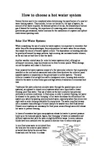
How it all works: Your solar hot water system is designed using evacuated tube solar collectors to harvest the sun‟s energy to heat water for domestic household use and/or radiant space heating. The major components of this system are Apricus collectors, insulated copper piping, propylene glycol (non-toxic antifreeze), a Caleffi Solar hot water tank and the Stiebel-Eltron pump station with differential temperature (Delta-T) controller. The schematic below illustrates an Apricus collector array with a Caleffi Solar tank integrated with electricity as the back up heat source.
ReVision Energy Domestic Solar Hot Water System Apricus 30-Tube Collector and 80-gallon Solar Storage Tank with integral electric backup Apricus 30
Household DHW
Evacuated Tube Collector
3
Stiebel Eltron Pump Station
Solar Hot Water Storage Tank with integral electric backup
Cold Water Feed
4
Basic system operation: This system is designed as a closed loop anti-freeze system, which means a fixed volume of heat transfer fluid is pumped in a continuous circuit between the solar collectors and the header located in the storage tank. When the differential temperature (Delta-T) sensor located on the rooftop solar collector senses that the temperature in the collector is greater than the temperature of the water stored at the bottom of the storage tank, the system pump will turn on and begin to circulate the heat transfer fluid. After being heated by the sun, this fluid is pumped through a header located in the bottom half of the storage tank. Heat is then transferred to the water stored in the tank, which supplies the domestic hot water lines for the house. The cooled anti-freeze fluid is then pumped back to the roof to be re-heated by the collector. When the Delta-T controller senses that the storage tank is hotter than the collector, the pump will turn off and the system will remain in standby mode until the collector is again hot enough.
The Collector: The Apricus AP is an evacuated tube collector, which consists of individual double walled glass tubes with an internal heat pipe. The air between the two glass walls is evacuated to act as an insulator to eliminate heat loss once the sunlight is captured by the collector.
The heat pipe (not shown) is located inside the glass tube and is used to absorb the heat energy that comes into the collector. The heat pipe consists of a thin hollow copper tube, which contains a water based fluid in a vacuum. Because this fluid is in a vacuum, it has a boiling point around 86 degrees F. As this fluid boils, steam rises up the heat pipe to the condenser located at the top of the heat pipe. 5
The heat pipe condenser plugs into a copper header located in the collector manifold. The systems heat transfer fluid is pumped through the manifold by which heat is then transferred from each evacuated tube and heat pipe.
6
The Tank: The Caleffi Solar storage tank works as an indirect fired hot water heater with one internal header coil.
The internal coil is used to get heat into the tank from the solar collectors on the roof. The coil is located at the bottom of the tank to allow for heating the entire water volume of the storage tank. The electrical element is located on the upper section of the storage tank providing back up heat if the solar panel is not providing enough heat to maintain the upper operating set point. An internal tank sensor will tell the back up electrical element to turn on when the tank is not to its desired temperature. The tank temperature is generally set to 120 degrees but can be adjusted if desired. The lower the temperature is set at the less fossil fuel you will consume.
Note: The electrical element may need to be reset if the tank reaches 180 degrees. To do so consult the tank manual. 7
The Anti-Scald Mixing Valve:
The cold water supply enters the bottom of the tank and the hot water supply is plumbed out of the top through a mixing valve. The mixing valve is used to ensure that the temperature of the hot water supplied at the tap is safe and desirable. A solar hot water storage tank has the potential to reach temperatures up to 180 degrees. When needed, the mixing valve allows cold water to mix with hot water from the storage tank to maintain a constant temperature. To ensure that the water at the faucets does not get dangerously hot, the mixing valve should be adjusted after the solar hot water system is installed. The best time to adjust the mixing valve is when the storage tank temperature is above 120 degrees. Note: The mixing valve does not make hot water. It simply adds varying amounts of cold water needed to maintain the temperature it is set for.
The Pump Station: The Stiebel-Eltron Flowstar pump station with Delta T controller provides the necessary valves, gauges, controls and pump for the solar hot water system to run and be monitored effectively.
8
The Delta-T Controller: The Stiebel-Eltron Delta-T controller uses external sensors in the solar collector and the storage tank to regulate the glycol pump. When the Delta-T controller senses that the collector is hotter than the storage tank (by a programmed value usually around 20 degrees) the glycol pump is turned on. When the collector temperature gets within a few degrees of the storage tank (again a programmed value usually around 7 degrees) the pump is switched off. The Delta-T controller has a display screen that gives the following information: collector temperature, storage tank temperature, optional third sensor temperature, pump speed “n %,” and hours of solar collection. The optional third sensor only functions to display the temperature at the top of the tank and serves as an indicator to the temperature of the water flowing into the mixing valve.
COL = Collector Temp TST = Tank Temp (bottom) S3 = Optional Sensor (top) HP = Hours of Operations
The use of the forward and backward buttons on the controller allows the operator to scroll through the various readouts on the display screen. For a more in-depth understanding of the Delta-T controller, consult controller manual. Unauthorized changing of controller settings voids warranty of installation!
The Glycol Antifreeze: The heat transfer fluid is used in a solar hot water system to absorb and transport heat from the solar collectors to the storage tank. All closed loop solar hot water systems require that the heat transfer fluid will not freeze in our climate, be able to withstand high temperatures, and to be non-toxic. To meet these requirements we install our solar hot water systems with a 40% mixture of propylene glycol. This glycol is able to withstand temperatures up to 350 degrees F, above which the glycol begins to degrade and become acidic. The normal lifespan of this type of glycol is between 5 to 10 years. Extended or multiple stagnation events will 9
shorten the life span of the glycol and will warrant a servicing of the glycol (see section on glycol maintenance).
Overheat Protection: Your solar hot water system is designed to protect itself from damaging overheat potential both in times of high sun and low demand, and in case of a power outage. If the tank temperature exceeds a preset maximum temperature, typically 180 degrees, the solar circulating pump will stop running. If the sun is still shining, the collectors will heat up rapidly once the flow has stopped and a small amount of heat transfer fluid in the collectors will begin to vaporize and push the rest of the fluid out of the collectors and into the solar expansion tank. In this „steam back‟ condition, you may notice system pressure increase above normal (as indicated by the system pressure gauge) and see collector temperatures above 300 or even 350 degrees. In addition, the „‟ indicator on the SOM6 controller will be illuminated. The red LED may also flash and the „!‟ indicator may be illuminated. This is normal, and the system will recover on its own once the collectors have cooled back down (i.e. overnight).
What you need to check and maintain: A periodic check of a few key components will ensure that your solar hot water system runs efficiently and effectively for many years to come. The pressure gauge located on the pump station is an important gauge that should be checked regularly. Refer to the record that was left by the installer of what your system pressure should be, this pressure will fluctuate with temperature variation. All readings should be in PSI. If system pressure drops below 10 PSI call ReVision Energy for service. The flow meter located inside the pump station (behind sliding insulation flap) can be checked by sliding down the insulation flap in front of it or by removing the cover of the pump station. When the pump is on at full speed, the float in the flow meter should indicate the presence of flow at some given flow rate in Gal/min (older models may be in L/min). Systems with a SOM plus controller have the option of variable speed refer to pump speed %. i.e. 100% equals full speed. The sensor reading on the Delta-T controller should be checked regularly. On a sunny day does the collector heat up, but not overheat? Does the storage tank heat up during the course of a sunny day (provided there is little to no demand for hot water). 10
The evacuated tubes in the collector should be checked periodically for loss of seal (fogging) or external damage.
N o rm a l T u b e
Fogged Tube
The Glycol antifreeze used in the system needs to be changed every 5-10 years. Inspect the color of the glycol through the flow meter. Green or Pink is good, brown is bad. If you suspect your glycol needs changing, call ReVision Energy for servicing. NEVER ADD OR REFILL THE SOLAR HOT WATER SYSTEM WITH ANYTHING BUT AN APPROVED PROPOLYENE GLYCOL PRODUCT! Our systems are filled with 40% propylene glycol.
Thank you for your business and your commitment to sustainability!
ReVision Energy www.revisionenergy.com 142 Presumpscot St. Portland, ME 04103
(207) 221-6342
91 W Main St, Liberty, ME 04949
(207) 589-4171
11
7 Commercial Drive, Exeter, NH 03833
(603) 501-1822