ANGULAR ACCELERATION AND MOMENT OF INERTIA Introduction Rotating an object requires that one overcomes that object’s rotational inertia, better known ...
ANGULAR ACCELERATION AND MOMENT OF INERTIA Introduction Rotating an object requires that one overcomes that object’s rotational inertia, better known as its moment of inertia. For highly symmetrical cases it is possible to develop formulas for calculating an object’s moment of inertia. The purpose of this lab is to compare two of these formulas with the moment of inertia measured experimentally for a disk and a ring. Equipment Computer with Logger Pro SW PASCO Rotational Apparatus + Ring Vernier Lab Pro Interface Smart Pulley + Photogate
Bubble Level Vernier Caliper Triple Beam Balance Rubber Band
String Mass Set
Note: If you are also going to determine the moment of inertia of the ring then you need to perform the first portion of this lab with only a single disk. If you use both disks you will not be able to invert them and add the ring to the system. The second disk does not have mounting holes for the ring. Only the disk with the step pulley has these positioning holes for the ring.
Theory If a force Ft is applied tangentially to the step pulley of radius r, mounted on top of the rotating disk, the disk will experience a torque τ
τ = Ft r = Iα
Equation 1.
where I is the moment of inertia for the disk and α is the angular acceleration of the disk. We will solve for the moment of inertia I by using Equation 1 and then compare it to the moment of inertia calculated from the following equation: Idisk = (1/2)MdR2 where R is the radius of the disk and Md is the mass of the disk. (Do not confuse R with r.) We can also place a ring on top of the disk and find its moment of inertia using Equation 1. We will first experimentally find the moment of inertia of both ring and disk together and subtract the moment of inertia of the disk from the total moment of inertia of
15d Moment of Inertia and Ang Accel - RGC
-1-
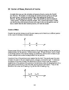
disk and ring together. Finally, we will compare this value for the moment of inertia of the disk to the following formula: Iring = (1/2) Mr (R02+Ri2 ) where Ro and Ri are the inner and outer radii of the ring respectively and Mr is the mass of the ring. Finding Ft , the Tangential force Ft = T
a
Weight = Mhg (Mh = hanging mass, g = 9.8 m/s2) Figure 1 A string will be attached to the small step pulley on top of the disk while the other end of the string will go over the smart pulley and then be attached to a hanging mass, Mh. The tangential force Ft on the disk is the tension T of the string. By studying Figure 1, Mhg - T = Mh a a is the acceleration of the hanging mass and a = αr where r is the radius of the step pulley used. Rearranging: T = Mh(g – a) = T = Mh(g –αr) The torque is just the Tension x Pulley Radius =>
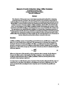
Figure 2
15d Moment of Inertia and Ang Accel - RGC
-2-
τ
= Tr = Iα,
Equipment Procedure NOTE: Rotating Apparatus Set Up: Setup the smart pulley and the mass pulley on opposite sides of the apparatus so that they don’t interfere with each other. You are measuring the diameters because they are easier to measure more accurately than a radius. However, the equations require the use of the radius. Record the diameter values but remember to divide by 2 to convert them to radii. You will be using just one disk in this experiment. That will be the one with the step pulley mounted on the top of it. If there are two disks on your apparatus lift them both off and removal the center axle that will probably come with them. Replace the axel in the platform and then replace the top disk. 1. Turn on the computer and load the smart pulley program from the Logger Pro folder. Open the LoggerPro application by double-clicking on its icon and then under the File menu click on the Open menu item. Under the Experiments folder, double click on the ‘Probes and Sensors’ folder and then double click on the ‘Photogates’ folder and then finally double click of the ‘Pulley’ file. Three graphs will be displayed: Distance, Velocity and Acceleration versus Time. You will be using the Velocity graph and doing a Linear fit to obtain “a” the Linear Acceleration of the rotating disk at its circumference. Then you will convert this into α, the Angular Acceleration, by dividing the Linear Acceleration by r, the radius of the Step Pulley. 2. Set Smart Pulley Diameter: Ensure that the pulley “length” is set to use the outside of the rim on the pulley and not the groove in the pulley. Under the Experiment menu click on Set Up Sensors. Select Show All Interfaces and then click on the photogate image. Select Set Distance or Length …, choose “Smart Pulley (10 Spoke) Outside Edge” (0.016m) 3. Set up the apparatus as shown in Figure 2. Level the disk. Measure and record the diameter d of the step pulley around which the string will be wound. Divide the diameter d by 2 to get the radius of the step pulley. Record the value in the Data Table. 4. Attach a string to the small step pulley on top of the disk. Pass the other end of the string over the mass pulley to a hanging mass, Mh. Rotate the disk to wind the string on the pulley in one smooth layer. Plug the smart pulley into the Logger Pro interface box connected to Digital input # 1. Note: The string from the step pulley to the mass pulley should be level.
15d Moment of Inertia and Ang Accel - RGC
-3-
Experimental Procedure 1. Click the Collect button at the top of the screen. After the button changes to Stop release the hanging mass and then click the Stop button before the weight hits the floor. Stop the disk before the string doesn’t completely unwinds. 2. The slope of the Linear Velocity vs Time graph will give the experimental value for the Linear Acceleration, a, for this combination of mass and pulley radius. Do a Linear fit to the velocity data to obtain “a” the Linear Acceleration at the edge of the rotating disk. Then convert this into α, the Angular Acceleration, by dividing the Linear Acceleration by R, the radius of the disk. Record the value of α in the Data Table. 3. Calculate and record the Torque
τ
= Mh(g –α r)r in your Data Table.
4. Repeat for four different masses. Do this for a total of five data sets. 5. Compare your experimental disk moment of inertia to the calculated value of the disk moment of inertia: Idisk = (1/2) MdR2 Using the Graphical Analysis program or Excel plot a graph with your five values of the Torque on the vertical axis and the corresponding Angular Acceleration values on the horizontal axis. Do a Linear Fit to your data points. Also determine the standard error in your slope using the LINEST function in EXCEL. The slope of this best fit line is the Best Fit experimental value of your moment of inertia. Record it on your Data Table. 6. Procedure for adding the ring to the disk. Remove the disk from the platform and turn it upside down and replace it on the platform. Place the ring on top of the inverted disk. 7. Repeat the above procedures that were used for the disk alone. In finding the moment of inertia of a ring, find the moment of inertia of both ring and disk together and then subtract the moment of inertia of the disk from the total moment of inertia. Do this with three different masses and pulley radii. Graph your Torque and Angular Acceleration values as before on a separate graph. The slope of the best fit line is the final experimental value of the total moment of inertia of the disk and ring combination.
Iring = ITotal - Idisk You should then compare this experimental value of Iring to the value calculated from the following equation: Iring = (1/2) Mr (R02+Ri2 )
15d Moment of Inertia and Ang Accel - RGC
-4-
where Ro and Ri are the inner and outer radius of the ring respectively and Mr is the mass of the ring. Lab Report Your report should follow the instructions in the document “Format for Formal Lab Reports.” Common Problems • Not measuring the step pulley diameter accurately. • Using diameters in the equations instead of radii. • Winding the string in more than one layer. • Winding the string on the wrong level of the step pulley. • Winding the string around the spindle instead of the step pulley.
15d Moment of Inertia and Ang Accel - RGC
-5-
DATA TABLE Step Pulley Diameter: ___________(m) Step Pulley Radius: r =___________(m) Disk: Md = _________(kg) R = __________(m) ICalc disk = (1/2)MdR2 = _________(kgm2 ) Ring: Mr = _________(kg) Ro = _________(m) Ri = ________(m) ICalc ring = (1/2) Mr (R02+Ri2 ) = __________(kg-m2) DISK (Assume the plastic weight hanger is 0.005 kg) Hanging Mass Mh (kg)
Hanging Weight Mhg (N)
Radius r Linear acc Ang acc α Torque τ of step a (m/s2) (rad/s2) (N-m) pulley From computer (Calculated) Mh(g –αr)r (m)
0.055 0.105 0.155 0.205 0.255
BEST FIT VALUE OF IDisk _______________ UNCERTAINTY ___________ % DIFFERENCE WITH ICalc disk _____________________________________ RING Hanging Hanging Radius r Mass Mh Weight of step (kg) Mhg pulley (N) (m)
Linear acc a (m/s2)
Ang Torque τ acc α (N-m) (rad/s2) Mh(g –αr)r
From computer
0.105
BEST FIT VALUE OF ITotal ______________ UNCERTAINTY ___________
0.205
BEST FIT VALUE OF Iring = ITotal - IDisk = __________