2004 IEEHPES Transmission 8 Distribution Conference 8 Exposition: Latin America 1
Ancillary Services - Reactive Power Support Optimization T. Sousa, Student Member, IEEE, J. A. Jardini, Fellow, IEEE, M. Masuda, and R. A. de Lima
Due to the importance of the reactive power supply to the Starting from the deregulated process of the system, several works have been published with the objective Electric Sector, there was the need to attribute responsibilities to of optimizing the supply of this service in order to comply several agents and to elaborate appropriate forms of with the restrictions imposed by the Electric Systems [ 11-[6]. remuneration of the services rendered by the same. A class of The current work proposes a methodology to optimize the services that has been receiving great emphasis after the reactive support service rendered by the generators agents and restructuring of the electric sector is the Reactive Support. With the objective of remunerating in an appropriate way the several identifying who offers and who uses this service. This agents involved in the supply and the use of this service, this methodology allows the agents to have conditions of work presents a methodology that seeks to optimize the reactive indicating the level of responsibility of each one, who may support rendered by the generating agents and to identify the eventually contribute to the necessity of rendering reactive level of responsibility of each agent that may use this service. The support service, proposed methodology uses a Linear Optimal Power Flaw, whose The proposed methodology uses a Linear Optimal Power objective function is to minimize the reactive power of the buses system. The problem complies with a group of restrictions. The Flow, whose objective function is to minimize the reactive proposed methodology was tested from a system of 8 buses and power of the buses system. The problem complies with a presented results that motivate the intensification of this research group of restrictions, like for instance, the levels of the system line. voltage, the reactive limits of the generators and the limits of reactive power of the loads. Keywords - Ancillary Services, Electric Power Systems, For verification of the proposed methodology, a system of Reactive Support. 8 buses was used and presented results that motivate the intensification of this research line. I. INTRODUCTION The work is organized as follows: Section I1 presents the In the last years, the electric sector has been undergoing a linear programming problem formulation used in this work. restructuring process, where the main changes are: the Section 111 presents the methodology used in the optimization deregulation of the activities that comprise the sector and the of the reactive support supplied by the generating agents. creation of a market responsible for the accomplished Section IV presents the tests and results obtained from the transactions. Along with the restructuring process, there proposed methodology and the final section presents the appeared the necessity of describing the different types of conclusions of this work. services with the objective of knowing them, organizing them by function and defining methodologies to identify who offers 11. PROBLEM FORMULATION OF LINEAR PROGRAMMING them and who uses these services. The formulations of the problems of Linear Programming A group of services that has received great attention in the (LP) used in this work will be presented as follows. The deregulation process of the electric sector is the group of services that contribute to the safety, the reliability and the problem of Linear Programming is used with the intention of quality to supply the electric power, the Ancillary Services. optimizing the reactive power of the system, minimizing the Among the several types of Ancillary Services, the reactive reactive support by the generators. For this purpose, it was power support is the service responsible for the supply or suggested the formulation of different problems of Linear absorption of reactive power destined to the voltage control of Programming, thus having different operation points. For the operation system, maintaining it within the established these different operation points, the system conditions were defined as follows: variation limits in the Electrical Power Systems. Abstrnd
-
"Base Solution"; "Sub Optimal Solution" and; "Super Optimal Solution."
This work was supported by the AES Tiet.5 S.A T. Sousa, J . A . Jardini and M. Masuda are with the Department of Electrical: Engineering, Sa0 Paulo University, Sa0 Paulo, BR (e-mail:
[email protected]). R. A. de Lima is with AES Tiete S. A., San Paulo, BR (e-mail:
[email protected]).
0-7803-8775-9/041$20.00 02004 IEEE
The "Base Solution" is the point of system operation, resulting from the problem of linear programming, which
75
2
considers that the reactive power values in the load buses of the system have a power factor smaller or equal to 0.95. The "Sub Optimal Solution" that is an optimized case in relation to the operation point denominated by "Base Solution". This is a feasible case of being accomplished in practice, but it has a solution not so optimized when compared with what was defined as "Super Optimal Solution". This solution is obtained starting from the problem of linear programming that considers that the reactive power values in the load buses of the system have a power factor smaller or equal to 0.98. And, finally, "Super Optimal Solution" is presented as the most optimized case of the system. This case presents the smallest reactive value supplied by the generators and it eventually may not be practiced since it demands, in some load buses, unitary power factor, however non capacitive. The formulations of the problems of linear programming that define the operations points described previousIy are presented as follows.
buses, respectively.
B. Formulation of the Linear Programming problem for 'Sub Optimnl Solution" The problem of Linear Programming for the "Sub Optimal Solution" can be represented mathematically through an optimization problem with restrictions Qf equality and inequality such as:
In the formulation presented for the solution denominated
as Sub Optimal, the last equation indicates that, for the load buses, the power factor can reach the value of 0.98 inductive. C. Formulation of the Linem Programmingproblem for 'Base Solution" The Linear Programming problem for "Base Solution" can be represented mathematically through an optimization problem with restrictions of equality and inequality such as:
A . Formulation of the Linear Programming problem for "Super OptimaI Solution"
The problem of Linear Programming for the "Super Optimal Solution" can be represented mathematically through an optimization problem with restrictions of equality and inequality such as:
Note that the algorithm of Linear Programming requires that all variables be positive. Equation (1) indicates the objective finction that is intended to minimize. For this, the objective function is represented by the sum of the final reactive power in the buses of the system. Equations (2) and (3) indicate that: the voltages of the all buses should be between the minimum and maximum limits, respectively; Equation (4) indicates that the generators are allowed to supply reactive in the limit of 0-5OOMVAr; Equation ( 5 ) limits the reactive power in the load buses (PQ) in the limit 0-SOOMVAr, thus allowing a unitary power factor; IS] is the matrix of voltage sensibility in relation to the determined reactive power variation starting from the matrix Jacobian resulting from the problem of load flow [7]; N is the total number of buses of the system; VOiis the value of the voltage magnitude of the initial operation point, Qfi and Qo, are the final and initial values of the reactive power in the
Note that far the equations presented for the solution denominated as Base, the last equation indicates that, for the load buses, the power factor can reach the value of 0.95 inductive. 111. PROPOSEDMETHODOLOGY
For the development o f the proposed methodology used to quantify the surplus reactive power supplied by the generator buses and to penalize the load buses proportionally to its influence in the surplus generation of reactive power, the following described process was used. As described in Section 11, three operational conditions for the system were defined. They are: condition whose presented solution is the "Base Solution", condition whose presented solution is the "Super Optimal Solution" and state whose presented solution is the "Sub Optimal Solution." Starting from the loading data and the physical configuration data of the system proposed for the tests, a program of systems analysis was used with the objective of simulating the load flow of this system. The solution resulting fiom the load flow Program is used in the formulation of the matrix sensibility used in the problem of linear programming. Once the matrix sensibility used as coefficients of the
76
~
3
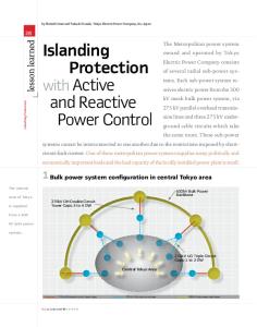
IV. TESTSAND RESULTS restrictions of inequality of the problem is determined, the next step is the formulation of the LP problem that represents With the objective of evaluating the proposed the operational condition that one wants to reach. methodology, some tests were accomplished beginning with a After the formulation of the LP problem, the next step is system of 8 buses. The tests accomplished from this system the execution of the same. In case the problem converges, the allowed a greater sensibility on the proposed methodology, results of the same should be adjusted in the data file of the thus allowing a greater domain on the variables of the load flow problem. Otherwise a new formulation for the LP problem. The system scheme used for the accomplishment of problem should be made. the tests is presented in Fig.2. After the data adjustment of the entrance problem of the load flow, the same is executed and in case it converges to a good solution, the problem is finalized. Otherwise, this new solution of the load flow problem will be a new data group for a new formulation of the PL problem. Then a new iteration i I begins. This iteration process occurs, because along with the load flow problem the non-linearity of the electric system is represented, which does not occur in LP. This deviation between the answer to the LP problem and the solution to the load flow problem is overcome after two or three iterations of the load flow problem [SI. Fig. 1 represents this iteration process. Fig 2. System of 8 b u s .
I
Sensibility Matrix Formulation
The generations and loads for the system of 8 buses are presented in Table I. In Table I the shunts (Qsh) least than zero in the buses means reactors and the load buses reactive power values greater than zero means inductive load.
I
TABLE I hlTIAL DATAOF WE SYSTEM OF
Ljrrear ProgrammingProblem
P(MW
Q
8 BUSES
PWIIW)
1
swing
Q
Qsb
(MVAr) (MVAr)
(MVAr) -
? Load Flow (U) -l Load 1 Load
Load
-
6
~~
Fig 1, Flowchart of the Optimization Problem of the Reactive Power Support.
Once the final solution of the defined operational conditions is obtained, an analysis in the reactive power generation is made and the reactive power economy attained from the optimization process is determined.
7
had
-
180.0
86.0
8
Load
-
290.0
48.0
-300.0
Table I1 presents the final condition of the system of 8 buses where the value of swing bus voltage is 1.05 PA.. The reactive power of generator and swing buses means that the generator provides power to inductive load, i.e., super excited generator. Starting from the data presented in Tables I and 11, the tests were camed out with the objective of determining the three operational conditions defined previously. For the first accomplished test, a problem of linear programming was formulated that could minimize the final
77
~
4
reactive power of the buses of the system subjected to the restrictions of voltage limits and the restrictions of reactive power limits. The reactive power of the load buses was limited to a power factor least than or equal to 0.95. Table Ill presents the results of the optimization process for the first accomplished test. The reactive indicated by PL in the load buses and the voltage of the generator and swing buses were be introduced in the load flow data. The system of equations of the problem of linear programming formulated for the first test is represented in Item 1I.C. For the solution presented in Table 111 the PL allocated the power factor load buses in 0.95.
final reactive power of the system buses subject to the restrictions of voltage limits and the restrictions of reactive power limits. The reactive power of the load buses were limited to a power factor less than or equal to 0.98. Table IV presents the optimization process results for the second test carried out. The system of equations of the problem of linear programming formulated for the second test is represented in Item 1I.B. The reactive indicated by PL in the load buses and the voltage of the generator and swing buses were be introduced in the load flow data. TABLEIV FMALCONDITION RESULTING FROM THE L a m FLOW OF THE TEST O W SOLUTION " FOR THE S Y S E M OF 8 BUSES
TABLEI1
SUB
FINAL CONDlTION RESULmG FROM THE LOAD FLOW FOR THE SYSTEM OF 8 BUSES
In Table IV the load buses power factor (cos$) remaining in 0.98. The reactive generated in Table 1V were least that the TABLEI11 last test due the load reactive were least. FINAL CONnlTION RESULTING FROM THE LOADFLOW OF THE The third test carried out deals with the operational point "BASESOLUTION '' TEST FOR THE SYSTEM OF 8 BUSES defined as "Super Optimal Solution ", For this test, a problem of linear programming was formulated that could minimize the final reactive power of the buses of the system subject to the restrictions of voltage limits and the restrictions of reactive power limits. The reactive power of the load buses was limited to a unitary power factor. Table V presents the results of the optimization process for the third test carried out. This test is defined as being the best solution as it provides freedom for the load buses to end up having unitary power factors. The system of equations of the linear programming problem formulated for the third test is represented in Item 1I.A. As already described previously, the result presented by Test 3 could not be applied in practice. This occurs because of the difficulty of demanding from the concessionaires that their Starting from the results presented by PL solution, it can be loads have a power factor close to the unitary value. The observed that the voltage values were not between the value reactive indicated by PL in the load buses and the voltage of limits that were 0.95p.u. for the inferior limit and I .05p.u. for the generator and swing buses were be introduced in the load the superior limit. With the objective of not to exceed the pre- flow data. established voltage buses the generator and swing voltage The results presented by Tests I and 2 are feasible and buses were adjusted to 1.05p.u., superior limit. show that according to the power factor presented by the Table 111 presents the result of the load flow after the loads, the generator buses need to generate a higher or lower adjustment of the voltage of the generator and swing buses reactive power. arbitrated in 1.05 P.u.. For this new solution, one can observe Starting from the obtained results, it is possible to make an that the voltage limits are being followed. analysis of the additional reactive power generated by the The second test accomplished deals with the operational generator buses. The presented results showed the necessity of point defined as "Sub Optimal Solution". For this test a linear a larger reactive power value generated to compensate the programming problem was formulated that could minimize the
78
5
K. Bhattacharya, and J. Zhong, "Reactive Power as an Ancillary
power factor of the load buses. This support of reactive power supplied by the generators with the objective of compensating the power factor of the load buses is dealt as a type of Ancillary Service. The power factor o f the 4,5,7 and 8 load buses presented in Table V were be fixed in 1.O.
Service," IEEE Trans. On Power System, vol. 16, No. 2, pp. 294-300, May2001. D. Pudjianto, S. Ahmed, and G. Strbac, "Allocation VAr Support Using LP and NLP based Optimal Power Flows," IEE P ~ Q c-. Gener. Transm. Di~trib.,vol. 149, NO. 4, pp. 377-383, Jul. 2002. Y. Dai, X. D. Liu, Y . X. Ni, F. S . Wen, Z. X. Han, C. M. Shen, and F. F. Wu, "A Cost Allocation Method for Reactive Power Service Based on Power Flow Tracing," Electric Power Systems Research, No. 64, pp. 59-
TABLEV m A L CONDlTIONRESUL'TLNG FROM THE LOAD FLOW OF THE TEST"SUPER OPTIMAL SOLUTION" FOR THE SYSTEM OF 8 BUSES
65,2003. H. Y. Yamind, "Review on Methods of Generation Scheduling in Electric Power System," Electric Power System Research, no. 69, pp. 227-248,2004. T. Sousa, V. A. S o w , and G. R. M. da Costa, " A Method for Determination of Candidates Buses to Reactive Allocation, " in X ERLAC, Puerto Igw4,2003. A. J. Wood, and B. F. Wollenberg, "Power Generation, Operation and Control", 1984.
V11. BIOGKAPH~ES Thales Sousa was born an June 23, 1978. He received his B.Sc. degree from the Sa0 Paulo Stste University (UNESP) in 2000. He obtained his M.Sc. degree at the University of Sao Paulo (USP) in 2003. Currently, he works as a researcher at GAGTD in the Polytechnic School at the University of Sa0
Paulo. He is working for his PhD. degree in the Department of Electrical Engineering of the latter institution. His research interests are power system operation and planning.
t
V. CONCLUSIONS The current work presented a methodology to determine in Josd Antonio Jardini, was born on March 27, 1941. He received his B.Sc. degree from the Polytechnic School at the University of Sa0 Paulo (USP) in an optimized way the support of reactive power supplied by 1963. Subsequently, he obtained his M.5c. and W.D. degrees in i970 and the generator buses, That objective was reached from an 1973, respectively, all from the Same institution. From 1964 to 1991 he optimization process, whose objective function is to minimize worked at Themag Eng. Ltd in the area of Power Systems & Automation and Transmission Lines projects. Currently, he i s a Professor in the Department of the final reactive power of the buses of the system. Engineering of Energy and Electric Automation at USP. He is a member of From the results attained, it is possible to note that CIGRE and was the Brazilian representative in the SC38 of CIGRE, Fellow according to the level of reactive power of the loads, the Member of IEEE and Distinguished Lecturer of IASIIEEE. Prof. Jardini's fields of interest are: Generation Automation, Transmission and Power generator buses should generate more or less reactive power Distribution. with the objective of compensating the power factor of the load buses. Mario Masuda, was born on June 25, 1948. He received his BSc. degree in The results presented showed that the electric systems can, Electrical Engineering from the Polytechnic School at the University of Sa0 in 1973. From 1973 to 1991, he was with Themag Eng. Ltda working most of the time, work in an operation point in order to Paulo, in the area of Power Systems & Automation and Transmission Lines projects. minimize the dependence of the load buses in relation to the From 1991 to 1997, he worked independently executing projects, supervising and teaching courses related to the installation of fiber optic cables in support of reactive power supplied by the generator buses. lines (OPGW). From 1997 to 2002, he worked at Furukawa and Ttie load buses operating in a point with greater transmission Constructions Ltd., with the lastly mentioned activities. Presently, he works as dependence in relation to the support of reactive power a researcher at GAGTD in the Polytechnic School at the University of Sao increase the necessity of generating reactive power from the Paulo. generator buses, thus having an increase in the active losses of the system. This surptus generation serves as parameter for the Rodrigo Alves de Lima was born on January 07, 1980. He received his B.Sc. degree in Electrical Engineering from the State University of Sao Paulo generator buses to demand through Ancillary Service (UNESP) with emphasis in power systems. Currently, he works at AES Tiet& contracts the supply of reactive power support. S A , in the field of regulation. Another form of compensating the additional reactive power requested by the load buses would be for them to allocate compensators in order to not require the reactive power support derived from the generator buses.
VI. REFERENCES J. W. Lamont, and J, Fu, "Cost Analysis of Reactive Power Support," IEEE Trans. On Power System, vol. 14, No. 3, pp. 890-898,Aug. 1999. [2] R. B. Gil, T. G. San Rondn, P. S. Martin, and J. J. Alba Rim, "Reactive Power Pricing: A Conceptual Framework for Remuneration and Charging Procedures," IEEE Trans. On Power System, vol. 15, No. 2, pp. 483-489, M a y 2000. [l]
79