IJRRAS 14 (3) ● March 2013
www.arpapress.com/Volumes/Vol14Issue3/IJRRAS_14_3_04.pdf
ANALYSIS OF AC CONTACTORS COMBINING ELECTRIC CIRCUITS, TIME-HARMONIC FINITE ELEMENT SIMULATIONS AND EXPERIMENTAL WORK Antônio Flavio Licarião Nogueira1 & Leonardo Jose Amador Salas Maldonado2 1,2 Universidade do Estado de Santa Catarina, Joinville, Santa Catarina, Brazil
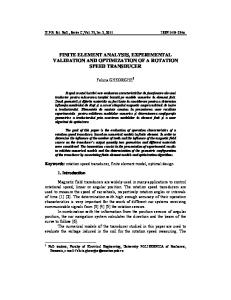
ABSTRACT The paper addresses complementary approaches to the calculation of electromagnetic parameters of an industrial alternating current (AC) contactor rated for 220 volts and 60 hertz. The methods of analysis include conventional electric circuits derived from measurements of terminal characteristics. The duality between interlinked electric and magnetic circuits is employed to calculate the contactor’s magnetizing reactance during a locked closing maneuver and during the closed-core configuration. The parameters obtained from the circuit analyses are compared to the more precise estimates of finite element analyses. Special attention is given to the subtle differences of circuit properties applied to the conductive regions containing driving currents as well as to regions where current is actually induced due to time variation of the magnetic flux. Attempt is made to facilitate the understanding of the physical phenomena related to the presence of eddy currents in the shading rings. Keywords: Contactor, Finite element analysis, Magnetic circuits, Magnetic forces, Shading ring. 1. INTRODUCTION The design and manufacture of electromechanical devices is a highly specialized process subject to many requirements due to the interconnected nature of the electrical, mechanical and thermal designs. Contactors are electromechanical switches employed in applications that require processes of electric circuit “making and breaking”, such as starter motors, electric vehicles, heaters, and lighting applications [1]. In the past, the design and development of electromechanical contactors has been based on extremely simple analytic models, supplemented by experience and intuition. By that time, any change in the device’s parameters would be time consuming and difficult to be accommodated by those traditional development methods. The decade of 1980 witnessed a shrinking number of experienced designers and, simultaneously, an increasing number of electric equipment manufacturers relying on computer-aided design (CAD) packages in their development processes. Major manufacturing companies and academic research groups have experienced that fast changing era in different ways, all depending on existing facilities and the nature of the equipment. Designers of electromechanical contactors and other type of forceproducing actuators, for example, were more likely to use finite element-based CAD systems than the designer of induction motors. The latter kind of electric equipment has always been more difficult to analyze using finite elements and has usually required a judicious balanced blend of classical and numerical methods. Some of the larger manufacturers have developed their own CAD facilities, locally or remotely, to assist them in their design tasks [2]. Alternatively, academic groups have developed their own CAD packages and worked together with manufacturing organizations to jointly perform a broad variety of experimental and simulated work [3]. The object of the present study is the characterization of an industrial alternating current (AC) contactor rated for 220 volts and 60 hertz. A photograph showing details of the double-E magnetic core at closed position, the location of air-gap regions and shading coils appears in figure 1.
513
IJRRAS 14 (3) ● March 2013
Nogueira & Maldonado ● AC Contactors Combining Electric Circuits
Figure 1. Photograph of the AC contactor, showing the double-E magnetic core, copper rings and air gaps.
The methods of analysis employed in the present study have been chosen considering that the laminated structures that form the contactors’ magnetic cores are usually designed and built using methods similar to those existent in the manufacturing processes of other electromagnetic devices such as transformers and industrial inductors [4]. The chosen analysis techniques are based on: (i) conventional equivalent electrical circuits; and (ii) duality between interlinked magnetic and electrical circuits. The conventional electrical circuits contain resistors and inductors that represent the physical phenomena in the device, like copper loss in the winding and stored energy in the magnetic core [5]. The electric circuits derived from magnetic circuits using the principle of duality are employed to estimate the magnetizing reactance of the contactor [6], [7], [8]. Values of the components that form the electrical circuits representing different operation stages of the contactor are compared with numeric estimates generated by the finite element analysis. 2. CONTACTORS AND FORCE PRODUCTION Electromechanical contactors contain three major components: the metallic contacts, the electromagnet, and the enclosure. The contacts are the current carrying part of the contactor, and are used to switch large amount of electric power, particularly the power consumption of electric motors. The electromagnet produces the magnetic force required to bring together the movable and fixed sections of the magnetic core. The enclosure is a frame made of insulating material that houses the electromagnet and the set of metallic contacts. The electromagnet usually contains a coil input which may be driven by either, an AC or DC supply. Over 80% of electromechanical contactors used in industries worldwide are equipped with AC powered coils. When industrial contactors are powered with DC supplies, the generated magnetic field H is constant with time, and so are the attractive forces between stator and armature. However, the alternating magnetic fields produced by AC powered coils generate alternating forces that drop to zero twice each cycle of the driving alternating current. This causes undesired mechanical vibration of the magnetized parts and metallic contacts. In a well-designed AC contactor, the magnetic force should never drop below the mechanical forces created by the restoring springs. In the illustration of figure 2, the dashed characteristic represents the time variation of per unit values of the AC driving current. It is assumed, for simplicity, an idealized purely sinusoidal time variation for the current. Per unit time variation of the magnetic force is represented by the solid characteristic. This force characteristic would represent the “odd” case where only the magnetic flux created by the driving coil circulates in the stator and armature of the AC contactor. To avoid the resulting undesired vibration or chatter, two conductive rings known as shading rings are placed at the external pole faces of the contactor’s stationary core. These shading rings play an important role in the overall performance of AC contactors. As a result of the time variation of the alternating magnetic flux crossing the region surrounded by the shading ring, eddy currents are induced in these conductive rings. The current flowing in the shading ring generates a magnetic flux out of phase with respect to the flux created by the driving coil current in a way that the net flux crossing the interfaces between the movable and fixed cores never drops to zero. This guarantees that, at the closed core configuration, the holding force does not drop to zero, thus eliminating the vibrations.
514
IJRRAS 14 (3) ● March 2013
Nogueira & Maldonado ● AC Contactors Combining Electric Circuits
Figure 2. The magnetic force drops to zero twice each cycle of the ac current.
Contactors are energy conversion devices wherein input electrical energy in the form of voltage and current is converted into magnetic energy. Before the closure process, the magnetic force necessary to produce mechanical motion is mainly provided by the useful or force-producing magnetic flux that crosses the air-gap regions that separate the movable and fixed sections of the core. Fringing flux around these gaps give a smaller but important contribution to the resulting magnetic force, and this effect must be included in any calculation procedure used to estimate the magnetic force with reasonable accuracy. For the configuration where the two sections of the magnetic core are separated, the evaluation of the contactor’s attractive force or drive force is easier because there is only interest in determining the global value of the force that appears at the air-lamination interfaces. In this case, traditional force calculation methods based on the virtual work principle or on the concept of Maxwell stress tensor may be employed [9], [10], [11]. The evaluation of the holding force, on the other hand, is far more complicated and force calculation methods intended to evaluate the generated forces between magnetized bodies in contact must be employed [12], [13], [14]. 3. LITERATURE REVIEW The literature documents extensive research in the analysis of the dynamic behavior of electromechanical contactors. The theoretical background of most research papers usually relies on the development of magnetic and electrical circuits that represent different operation stages of a given electromechanical contactor. Results obtained from the magnetic and/or electric circuit analyses provide the basic set of mathematical equations and boundary conditions required by the computational modeling tasks. Data required by computer programs are sometimes supported by experimental work. Measurement of electrical variables like terminal voltages, currents and power consumption are easily performed with the use of, e.g. a simple power quality analyzer. Measurement of mechanical variables like displacement and spring forces, on the other hand, are more difficult to perform and requires the use of specially constructed and instrumented sensors and test devices. Different numeric methods have been used to predict the dynamic response of AC contactors. Computer software based on the finite element method is the most common in the computational modeling of the dynamic characteristics of electromechanical contactors [15]. There are, on the other hand, university groups that have carried out their dynamic simulations and engineering education activities with the aid of Matlab-Simulink platforms [16], [17]. Many practical problems faced by industrial designers of electromechanical contactors are related to the mechanical displacement of the contactor’s components, and the resulting effects of the closure impact. The impact that occurs during the closure operation is the origin of contact bounce, i.e. a sequence of re-opening operations that generate electric arcs. Each bounce is in fact a very fast “break and make” operation, during which the electric arc is not usually extinguished. Electric arcs can cause severe erosion of the metallic contacts and, as a consequence, the lifespan and reliability of the contacts may be dramatically reduced. Since the early 1990s, several researchers have focused attention on the characterization of the phenomena that occur immediately before contacts closure or immediately after contacts separation [18], [19], [20]. By the same time, attempts to minimize the effects of contact 515
IJRRAS 14 (3) ● March 2013
Nogueira & Maldonado ● AC Contactors Combining Electric Circuits
bounce based on the reduction of the contactor’s kinetic energy at impact time have been made by major manufacturers of electric equipment [21]. In recent years, the merits of AC permanent-magnet contactors such as high reliability and low energy consumption when compared to the conventional electromagnetic contactors has motivated industrial designers to study the dynamic and motion characteristics of this new class of contactors [22], [23], [24]. Other relevant contributions to the art are the recent publications with emphasis on the use of electronic control units employed to achieve contactor’s multi-objective optimization targets [25], [26], [27], [28]. 4. PROBLEM DESCRIPTION The contactor’s electromagnet consists of a single coil wound around the central limb of the lower or stationary portion of the double-E laminated core. For the closed-core configuration, the size of each rectangular window is 3.2 cm by 1.05 cm. The driving coil contains 5,000 turns and its height is approximately 1.4 cm. The main geometrical dimensions are indicated in figure 3, and the depth of the device is 1.2 cm.
Figure 3. Sketch of the contactor’s electromagnet, dimensions in centimeter. Not to scale.
The contact between the two magnetized portions of the E-shaped magnetic cores is, in fact, restricted to small regions located at the side limbs. The innermost portions of the magnetized surfaces in contact are known as unshaded poles, whereas the regions surrounded by the shading rings are known as shaded poles. These geometrical features are illustrated in figure 4. The gap separating the two portions of the central limb is 8.0 mm when contactor is open and only 0.4 mm at the closed core configuration.
516
IJRRAS 14 (3) ● March 2013
Nogueira & Maldonado ● AC Contactors Combining Electric Circuits
Figure 4: Shaded and unshaded poles.
5. DERIVATION OF ELECTRICAL CIRCUITS 5.1. Conventional Equivalent Electrical Circuit AC contactors may be described by the conventional electric circuit shown in figure 5. The components of the circuit correspond to the physical phenomena in the device. The resistor Rw in the horizontal branch accounts for the ohmic loss in the winding of the exciting coil. The inductor L in the vertical branch accounts for the magnetic field energy storage in the magnetic cores and leakage fields in the windows and air gaps. The shunt resistor R in the vertical branch represents the active power loss in the magnetic cores.
Figure 5: Conventional equivalent electric circuit of the contactor.
To validate the proposed equivalent circuit, measurements of the various terminal electric variables have been carried out. The first set of measurements concern a closing maneuver, whereas the second one refers to the configuration where the movable and fixed cores are in contact, from now on referred to as the closed core configuration. Information related to the readings of power consumption is presented in figure 6. In the illustration, P denotes the active power, Q denotes the reactive power, and S is the complex power. In this illustration, both triangles are scaled to the same view size, and the subscripts “1” and “2” refer to the power consumption of the locked closing maneuver and closed core configuration, respectively. A careful observation of the illustration shows that: (i) the power consumptions associated the two operations differ significantly; (ii) the power required to overcome the mechanical force generated by the mechanical springs and bring together the movable and fixed magnetic cores is considerably higher; (iii) once the two magnetic cores are in contact, the power consumption is 517
IJRRAS 14 (3) ● March 2013
Nogueira & Maldonado ● AC Contactors Combining Electric Circuits
significantly reduced, particularly the consumption of the active power P that undergoes a fold reduction of approximately 15 times.
Figure 6: Contactor’s power consumption; (a) Locked closing maneuver; (b) Closed core configuration.
5.1.1. Contactor’s locked closing maneuver To facilitate the measurement of the terminal electric quantities related to the locked closing maneuver, the armature movement has been blocked by the presence of a non-magnetic rubber spacer 8 millimeter high inserted in the airgap regions that separate the fixed and movable cores. Measured values of root-mean-square (rms) applied voltage and current, together with the registered power consumption at a 60-hertz operation are summarized in table 1. The table also includes the values of cos(), the power factor, and the electric resistance Rw of the exciting coil. The power factor has been computed from the readings of active power P and apparent power S. Table 1: Measured 60 Hz input signals related to the locked closing maneuver.
Irms (mA) Vrms (V) P (W) Q (VAr) S (VA) cos() Rw (Ω)
268.00 218.00 48.30 33.10 58.60 0.82 534.00
The conventional equivalent electrical circuit related to the locked closing maneuver is presented in figure 7. The sequence of calculations relating the measured terminal characteristics and the circuit’s components is presented in the Appendix A.
Figure 7: Conventional equivalent electrical circuit for the locked closing maneuver.
5.1.2. Contactor’s closed core configuration The electrical characteristics of the conventional equivalent electrical circuit that represents the physical phenomena in the closed core configuration differ significantly from those that form the circuit for the locked closing maneuver. Measured values of the input signals for the closed core configuration are summarized in table 2. The conventional 518
IJRRAS 14 (3) ● March 2013
Nogueira & Maldonado ● AC Contactors Combining Electric Circuits
equivalent electrical circuit related to the latter state of operation is presented in figure 8, and the sequence of calculations is presented in the Appendix A. Table 2. Measured 60 Hz input signals related to the closed core configuration.
Irms (mA) Vrms (V) P (W) Q (VAr) S (VA) cos() Rw (Ω)
50.50 222.00 3.20 10.90 11.40 0.29 534.00
Figure 8: Conventional equivalent electrical circuit for the closed core configuration. 5.2. Duality between Magnetic and Electric Circuits In order to derive the equivalent electrical circuit of a given device employing the duality between interlinked electric and magnetic circuits, the starting point may be a draft of a magnetic structure containing the parts that directly affect the electromagnetic action of the device under analysis. This is followed by the creation of a magnetic circuit containing sources of magnetomotive forces and a number of interconnected lumped elements known as reluctors. These components represent the storage of magnetic energy in magnetic cores, air gaps, fringing flux around the gaps, and leakage fields. In the definition of the lumped elements, each region where the magnetic flux density B is more or less uniform is represented by an element of a given magnetic reluctance. The relationship between the variables is
F ,
(1)
where F is the magnetomotive force, is the magnetic reluctance, and is the magnetic flux. The theory related to the derivation of the dual equivalent electrical circuits is presented in references [6-8]. The estimates of the contactor’s magnetizing inductance obtained by the principle of duality for the two configurations are summarized in table 3. Table 3. Contactor’s magnetizing inductance obtained by the principle of duality.
Locked closing maneuver Closed core configuration
0.82 H 10.46 H
6. FINITE ELEMENT ANALYSIS Numerical field solutions have been obtained using the two-dimensional Cartesian magnetostatic processors and solver of the simulation software FEMM [29]. To permit two-dimensional analysis, all magnetic structures that represent the contactor are considered longitudinally uniform, and the depth of these planar structures is 1.2 cm. The solutions are obtained for the magnetic vector potential A, and first-order triangular finite elements are employed in all computations. All numerical models include an external circle concentric with respect to the centre of the magnetic structures. These circles are not shown in the illustration of figure 3. The radius of each circle is 10 cm, and represents about three times the length of the smallest circular boundary that completely encircles the rectangular geometry of the 519
IJRRAS 14 (3) ● March 2013
Nogueira & Maldonado ● AC Contactors Combining Electric Circuits
contactor. All problems’ boundary conditions are homogeneous Dirichlet, wherein the condition A=0 is prescribed on the external circular boundary [30]. All finite-element calculations are performed by specifying a 60-hertz frequency in the problem definition. The specification of a non-zero frequency automatically implies a time harmonic analysis, in which all field quantities oscillate at the prescribed frequency. To model the magnetic core in the finite element model, all regions containing the thin laminations are specified by the homogeneous composite material, commercially known as “Carpenter Silicon Core Iron A 1066C Anneal”. The specifications include lamination thickness of 0.5 mm and fill factor of 80%. 6.1. Regions with conductive materials The numeric calculation of eddy currents, i.e. currents that arise from time-varying magnetic fields present in conductive materials is a task of major interest in the analysis of AC contactors. Stranded coils that carry the excitation current are usually modeled by two non-contiguous regions, and the properties of these regions include the specification of the coil’s number of turns and the terminal current. In the finite-element program FEMM, each pair of regions representing a stranded coil must be defined as series-connected [29]. On the other hand, the constraints applied to the conductive regions where current arises from time-varying magnetic fields, i.e. regions where the eddy currents are actually induced, are quite different. Each pair of regions representing, e.g. the two sides of a shading coil must be defined as parallel-connected. By applying a parallel-connected circuit with zero net current to each side of a shading coil or any pair of physically connected solid conductors, one guarantees that the “computed” total current in one region will return through the other region intended to be in fact parallel-connected to the first one. The constraints applied to the regions that represent the contactor’s driving coil and one of the shading coils are summarized in table 4. It is worth noting that the number of turns assigned to a given region that represents the endside of a given coil can be either a positive or a negative number. The sign on the number of turns indicates the direction of current flow associated with a positive-valued circuit current. Table 4. Definition of properties for conductive regions
Driving coil (closed core) Shading coil
Number of turns Peak current (mA) Number of turns Peak current (mA)
Left-hand side region -5,000 71.41 -1 0
Right-hand side region +5,000 71.41 +1 0
Connection between the two regions Series Parallel
7. NUMERICAL RESULTS 7.1. Magnetizing inductances For the two operating conditions considered in the analysis, the magnetizing inductances of the contactor have been determined by three different methods, and the computed values are summarized in table 5. Per cent errors indicated in table 5 are computed taking the more precise finite element estimates as benchmarks. Table 5. Contactor’s magnetizing inductances obtained by three different methods. Values in henry.
Configuration Locked closing maneuver Closed core
Conventional electric circuit Inductance (H) Error 0.85 23.4% 10.43 3.9%
Dual electric circuit Inductance (H) Error 0.82 26.1% 10.46 4.4%
Finite elements Inductance (H) 1.11 10.02
The amount of reactive power consumption is frequency dependent and a direct consequence of the magnitude of the magnetizing reactance. Values of reactive power consumption obtained by both, measurements and finite element computations are compared in table 6. Finite element estimates are taken as benchmarks. Table 6. Contactor’s reactive power consumption obtained by measurements and finite element computations.
Configuration Locked closing maneuver Closed core
Measurements Reactive power (VAr) 33.10 10.90
520
Error 9.9% 4.0%
Finite elements Reactive power (VAr) 30.11 11.36
IJRRAS 14 (3) ● March 2013
Nogueira & Maldonado ● AC Contactors Combining Electric Circuits
7.2. Eddy currents in the shading rings The major effect of the shading rings is the creation of a magnetic flux out of phase with respect to the flux created by the driving coil. In this way, one guarantees that the net flux crossing the interfaces between the movable and fixed cores never drops to zero. This guarantees that the holding force, which varies with the magnitude of flux squared, does not drop to zero. A quantity of major interest in the time-harmonic finite element analysis is the magnitude of the currents induced in the shading rings. For the closed core configuration, the computed magnitude of the current induced in each ring is 47.159 A. The understanding of the physical phenomena is facilitated by observing the operation condition wherein all circulating flux arises from the eddy currents in the shading rings. To simulate this condition, the main coil is specified as a series-connected circuit with zero current, and a series-connected circuit with currents of +47.159 A and -47.159 A is applied to each side of the shading coils. Results of this simulation can be observed in figure 9.
Figure 9. Flux lines and density plot of the B-field when all flux arises from the eddy current in the shading rings.
Observation of the plot shows that, the circulating flux created by the eddy current is somewhat restricted to the regions around the shading rings. Most of the flux crosses the shading ring transversally in the vertical direction, and closes its path through the unshaded pole face. Only a small proportion of the total generated flux makes its return path through the central limb. At normal operation, the device’s flux distribution results from the combined effect of two sources of magnetic flux: (i) the flux due to the magnetomotive force of the main coil; and (ii) the flux due to the magnetomotive force of the shading rings. For the closed core configuration, the peak driving current is 71.41 mA, which corresponds to the measured rms current of 50.5 mA. The magnetomotive force due to the 5,000-turn coil is 357.09 A-turn, the magnetomotive force due to each single-turn shading ring is 47.159 A-turn. Results of this simulation can be observed in figure 10.
521
IJRRAS 14 (3) ● March 2013
Nogueira & Maldonado ● AC Contactors Combining Electric Circuits
Figure 10. Flux lines and density plot of the B-field showing the combined effect of the main coil and shading rings.
Observation of the plot shows that the combined effect of the magnetomotive forces of the main coil and shading rings leads to a decrease in the flux crossing the shading rings and, simultaneously, a substantial increase in the flux crossing the unshaded region. To make the matter concrete, a quantitative evaluation of the flux distribution along the interface of the two core portions has been carried out. The first operation condition concerns the flux distribution for the contactor operating without the shading rings, whereas the second one refers to the contactor operating normally with the shading rings. The problem that represents the contactor’s operation without shading rings is easily defined by means of the artifice of material re-identification. In this case, the two rectangular regions representing the end-sides of the shading rings should be specified as completed filled by air or any other nonmagnetic and non-conductive material. The inspection of the B-field is made along the interface of the fixed and movable cores. In the two-dimensional view of figure 10, the interface is represented by the straight line segment that bisects the drawing. Results of this inspection are presented in figure 11. In this graph, the added arrows help to spot the variations of magnitude of the B-field related to the operating condition with shading rings across the central limb and unshaded poles.
Figure 11. Magnitude of the B-field along the interface of the fixed and movable cores; (a) The solid characteristic represents the operation without shading rings; (b) The characteristic with circles represents the operation with shading rings.
522
IJRRAS 14 (3) ● March 2013
Nogueira & Maldonado ● AC Contactors Combining Electric Circuits
Observation of the graph presented in figure 11 helps to understand the physical phenomena related to the presence of eddy currents in the shading rings. It is worth noting that the generation of flux by the eddy currents is, in fact, a reaction of the electromagnetic system to change in its circulating flux. In other words, the flux of the shading rings bucks or opposes any change or variation in the circulating flux. One of the effects is the reduction of the flux crossing the central limb, and this is easily observed in the central portion of the graph. Along the central limb, the average magnitude of flux density undergoes a fold reduction of 12%. Simultaneously, it is possible to spot a substantial increase of 36.6% in the flux density crossing each unshaded pole. 8. CONCLUSIONS Three different analysis techniques have been employed in the analysis and characterization of an industrial AC contactor rated for 220 volts, 60 hertz. Two operating conditions are considered: a locked closing maneuver and the configuration where the movable and fixed cores are in contact. Conventional electric circuits containing elements that represent physical phenomena like ohmic loss and energy storage have been derived from measurement of terminal characteristics like voltage, current and power consumption for the two operating conditions. Dual electric circuits have been derived to obtain estimates of the contactor’s magnetizing inductance at the two operating conditions. The main contribution of the work is related to the numeric calculation of eddy currents. The discussion places emphasis to the numerical constraints applied, in different ways, to the conductive regions where current arises from time-varying magnetic fields and regions containing stranded coils that carry the driving currents, respectively. Two variations of the contactor’s closed-core configuration have been considered in order to illustrate the effect of the shading coils. 9. APPENDIX A: DERIVATION OF CONVENTIONAL ELECTRICAL CIRCUITS 9.1. Contactor’s locked closing maneuver The relationship between the electric quantities and the parameters of the conventional equivalent circuit related to the locked closing maneuver are discussed in the following. For an applied rms voltage of 218.0 V, the measured rms source current is I=268 mA. The computed voltage drop V1 across the resistor Rw that represents the DC winding resistance is V1 IRw (268 103 )(534) 143.11 V. The voltage across the parallel impedance RL is V2 V V1 218.00 143.11 74.89 V. The computed mean active power Pw that represents the losses due to the winding resistance is Pw Rw ( I ) 2 35.34 W. The mean active power P that represents losses due to the magnetic core can be calculated as the difference P Ps Pw 48.30 38.35 9.95 W. where Ps represents the measured active power supplied by the AC source. The value of the resistor R that represents the magnetic core losses may be computed by 2 2 R (V2 ) (74.89) 563.67 . P (9.95) The current Ir in the resistive branch is then I r V2 74.89 132.86 mA. R 563.67 The current Ix in the inductive branch is I x (I )2 (I r )2 I x (268 10 3 ) 2 (132.86 10 3 ) 2 232.75 mA.
The value of the inductive reactance XL is frequency dependent and, for a 60-hertz power supply, can be calculated from the lagging current Ix, X L L V2 74.89 321.76 m. Ix 232.75 where ω=2πf is the angular frequency of the power supply. The inductor shown in the vertical leg of the circuit accounts for the energy stored in the leakage fields, including fringing. The circuit is fed by a 60-hertz power supply and the value of the inductor L is given by 523
IJRRAS 14 (3) ● March 2013
L XL
321.76 10
3
120
Nogueira & Maldonado ● AC Contactors Combining Electric Circuits
0.854 H.
9.2. Contactor’s closed core configuration The relationship between the electric quantities and the parameters of the conventional equivalent circuit related to the contactor’s closed configuration are discussed in the following. For an applied rms voltage of 222.0 V, the measured rms source current is I=50.50 mA. The computed voltage drop V1 across the resistor Rw that represents the DC winding resistance is V1 IRw (50.5 10 3 )(534) 26.97 V. The voltage across the parallel impedance RL is V2 V V1 222.00 26.97 195.03 V. The computed mean active power Pw that represents the losses due to the winding resistance is Pw Rw ( I ) 2 534.00(50.50 103 ) 2 1.36 W. The mean active power P that represents losses due to the magnetic core can be calculated as the difference P Ps Pw 3.20 1.36 1.84 W. where Ps represents the measured active power supplied by the AC source. The value of the resistor R that represents the magnetic core losses is 2 2 R (V2 ) (195.03) 20.672 k. P (1.84) The current Ir in the resistive branch is then I r V2 195.03 9.43 mA. R (20.672 103 ) The current Ix in the inductive branch is I x (I )2 (I r )2 I x (50.50 10 3 ) 2 (9.43 10 3 ) 2 49.61 mA.
The value of the inductive reactance XL is frequency dependent and, for a 60-hertz power supply, can be calculated from the lagging current Ix, X L L V2 195.03 3931.26 . Ix 49.61 103 where ω=2πf is the angular frequency of the power supply. The inductor shown in the vertical leg of the circuit accounts mainly for the energy stored in the magnetic core. The circuit is fed by a 60-hertz power supply and the value of the inductor L is given by L X L 3931.26 10.43 H. 120 10. ACKNOWLEDGEMENT The authors are grateful to David Meeker (
[email protected]) for the use of the finite element CAD system FEMM. The authors give thanks to the Brazilian Federal Agency for Postgraduate Studies (CAPES) for the sponsored access to several scientific web sites. 11. REFERENCES [1] J.-R. R. Ruiz, A. Garcia, J. Cusidó, M. Delgado, “Dynamic model for AC and DC contactors – simulation and experimental validation”, Simulation Modeling Practice and Theory, vol. 19, pp. 1918-1932, 2011. [2] A. de Beer, S.J. Polak, A.J.H. Wachters, J.S. van Welij, “The use of PADDY for the solution of 3-D magnetostatic problems”, IEEE Trans. on Magnetics, MAG-18, pp. 617-619, 1982. [3] N. Sadowski, J.P.A. Bastos, A.B. Albuquerque, A.C. Pinho, P. Kuo-Peng, “A voltage fed AC contactor modeling using 3D edge elements”, IEEE Trans. on Magnetics, vol. 34, no. 5, pp. 3170-3173, 1988.
524
IJRRAS 14 (3) ● March 2013
Nogueira & Maldonado ● AC Contactors Combining Electric Circuits
[4] C. Álvarez-Mariño, F. de Leon, X. M. López-Fernández, “Equivalent circuit for the leakage inductance of multiwinding transformers: unification of terminal and duality models”, IEEE Trans. on Power Delivery, vol. 27, no. 1, 2012. [5] D.A. Lowther and P.P. Silvester, Computer-aided design in magnetics, Springer-Verlag, New York, 1986, pp. 176. [6] E. Colin Cherry, “The duality between interlinked electric and magnetic circuits and the formation of transformer equivalent circuits”, Proc. Physical Society, vol. 62B, pp. 101-111, 1949. [7] L. Dixon, “Deriving the equivalent electrical circuit from the magnetic device physical properties”, Magnetics Design Handbook (Ed. Texas Instruments Incorporated, USA, 2001). [8] N. Chiesa, Power transformer modelling advanced core model, MSc thesis, Politecnico di Milano, Italy, 2005, pp. 29-39. [9] A.F. Licarião-Nogueira, D.C.B Pereira Junior, “Surface integration and energy-based approaches to calculate global forces in magnetic actuators”, in Proc. of the 7th Brazilian Congress of Electromagnetism (MOMAG), Belo Horizonte, Brazil, 2006. [10] A.F. Licarião Nogueira, “Performance analysis of the method of mean and difference potentials for magnetic force calculation: a technique that combines the principles of virtual work and superposition”, International Journal of Research and Reviews in Applied Sciences, vol. 11, no. 2, pp. 202-213, May 2012. Available: http://www.arpapress.com/Volumes/Vol11Issue2/IJRRAS_11_2_04.pdf [11] A.F. Licarião Nogueira, “Computation of magnetic forces in moving coil drivers using mean and difference potentials”, International Journal of Research and Reviews in Applied Sciences, vol.13 , no. 2 , pp. 398-405, November 2012. Available: http://www.arpapress.com/Volumes/Vol13Issue2/IJRRAS_13_2_04.pdf [12] J.P.A. Bastos, N. Sadowski, Electromagnetic modeling by finite element methods, New York: Marcel Dekker, 2003, pp. 367-418. [13] H.S. Choi, I.H. Park, S.H. Lee, “Generalized equivalent magnetizing current method for total force calculation of magnetized bodies in contact”, IEEE Trans. on Magnetics, vol. 42, no. 4, pp. 531-534, 2006. [14] D.-H. Kim, D.A. Lowther, J.K. Sykulski, “Efficient force calculations based on continuum sensitivity analysis”, IEEE Trans. on Magnetics, vol. 41, no. 5, pp. 1404-1407, 2005. [15] R. Gollee, G. Gerlach, “A FEM-based method for analysis of the dynamic behavior of AC contactors”, IEEE Trans. on Magnetics, vol. 36, no. 4, pp. 1337-1340, 2000. [16] J.-R. R. Ruiz, A.G. Espinosa, “A novel parametric model for ac contactors”, IEEE Trans. on Magnetics, vol. 44, no. 9, pp. 2215-2218, 2008. [17] J.-R. R. Ruiz, A.G. Espinosa, L. Romeral, “A computer model for teaching the dynamic behavior of AC contactors, IEEE Trans. on Education, vol. 53, no. 2, pp.248 -256, 2010. [18] J.W. McBride, “An experimental investigation of contact bounce in medium duty contacts”, IEEE Transactions on Components, Hybrids, and Manufacturing Technology, vol. 14, no. 2, pp. 319-326, 1991. [19] W.F. Rieder, “Low current arc modes of short length and time: a review”, IEEE Transactions on Components and Packaging Technologies, vol. 23, no. 2, pp. 286-292, 2000. [20] M.P. Paisios, C.G. Karagiannopoulos, P.D. Bourkas, “Model for temperature estimation of dc-contactors with double-break main contacts”, Simulation Modelling Practice and Theory, vol. 15, pp. 503-512, 2007. [21] U.S. Patent 5 128 825, Property of Westinghouse, July 7, 1992. [22] S. Fang, H. Lin, S.L. Ho, “Magnetic field analysis and dynamic characteristic prediction of AC permanent-magnet contactor”, IEEE Trans. on Magnetics, vol. 45, no. 7, pp. 2990-2995, 2009. [23] X. Wang, H. Lin, S.L. Ho, S. Fang, P. Jin, “Analysis of dynamic characteristics of permanent magnet contactor with sensorless displacement profile control”, IEEE Trans. on Magnetics, vol. 46, no. 6, pp. 1633-1636, 2010. [24] S. Fang, H.Y. Lin, S.L. Ho, X.B. Wang, P. Jin, “Characteristic investigation of permanent magnet actuator for vacuum contactors operating with an intrinsically safe low voltage”, Science China Technological Sciences, vol. 55, no. 6, pp. 16881694, 2012. [25] W. Tarczynski, T. Hejman, D. Smugala, “Computer-controlled testing system for investigating the dynamic characteristics of contactors with a.c. eletromagnet drives”, Measurement, vol. 33, pp. 313-323, 2003. [26] H.S. Yoon, Y.H. Eum, Y. Zhang, C.S. Koh, “Multi-objective optimal design of a single phase AC solenoid actuator used for maximum holding force and minimum eddy current loss”, Journal of Electrical Engineering & Technology, vol. 3, no. 2, pp. 218-223, 2008. [27] P.M. dos Santos Dias de Moraes, A.J. Perin, “An electronic control unit for reducing contact bounce in electromagnetic contactors”, IEEE Transactions on Industrial Electronics, vol. 55, no. 2, pp. 861-870, 2008. [28] Chieh-Tsung Chi, Chien-Chi Chao, “Development of a new IC-controlled interchangeable AC and DC contactor, Analog Integr Circ Process, vol. 63, pp. 245-253, 2010. [29] D. Meeker, Finite element method magnetics, user’s manual. Available: http://www.femm.info/Archives/doc/manual42.pdf [30] A.F. Licarião Nogueira, “A case study on open boundary techniques for electromagnetic field problems with translational symmetry”, Journal of Microwaves, Optoelectronics and Electromagnetic Applications, vol. 9, no. 1, pp. 20-33, 2010. Available: http://www.jmoe.org/site-number?id=7
525