Air Pollution Scenarios towards 2030 in China: Emissions and Air Quality Prof. Kebin HE Department of Environmental Science and Engineering, Tsinghua University, Beijing 100084, China
Workshop on Hemispheric Transport of Air Pollution: Emission Inventories and Future projections Beijing, China October 18th - 20th, 2006
Outlines
Background Working framework Scenario development Modeling methodology Modeling results Discussion
Outlines
Background Working framework Scenario development Modeling methodology Modeling results Discussion
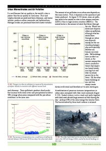
Historical emissions Activities
Energy Consumption
100000
5000
St eel Cement Chemi cal Fer t i l i zer
80000 70000
4500 4000 3500 3000
2500
50000
2500
Hydr o NG 1000 oi l 500 coal
40000
2000
2000
30000
1980 82
84
86
88
90
92
94
96
MTCE
0
2500
1500
20000 10000
3000
1500
2000
Tg
104 tons
60000
104 tons fertilizer
90000
0
98 2000 2002 2004
1500
1000
3000
1000
2500
500
2000
0
1500
1978 80
1000 500 0 1980 82
84
86
88
90
92
94
96
SO2 PM
500
Vehi cl e Popul at i on
4
10 vehi cl es
Emissions
98 2000 2002 2004
82
84
86
88
90
92
94
0 96 98 2000 1997 1998
02
04
1999
2000
2001
2002
2003
2004
2005
Why emission projection is needed
Rapid development in “10th five years”, but Only Environment target is not met 25490Gg
¾ SO2:
19950Gg
(Emitted in 2005)
(2000)
18000Gg (Target in 2005)
Aggressive environment target for “11th five years” Projection of emissions is needed to support policy making
Outlines
Background Working framework Scenario development Modeling methodology Modeling results Discussion
Work Scope
Purpose: To simulate energy consumption and emission of air pollutants up to 2030
Spatial Scope: China National Level
Time Step: 2000 (Base Year), 2005, 2010, 2020 and 2030
EI sectoral scope: power, industry, domestic, transportation and biomass burning
Pollutants: SO2, NOx, CO, VOC, BC and OC
Framework Energy
Environmental
Technology
Technology
Options
Options
Activities/Energy Use
Emissions
Air Quality
Tool: LEAP model
Tool: Updated Trace-P EI
Tool: Models-3/CMAQ
Energy
Environmental
Policy
Policy
Options
Options
Tech based EI methodology Energy consumption
Environmental Key of emission From LEAP projection Policies / tech
Tech character Tech split Activities
Fuel Quality
Unabated Emission Factor Abatement Efficiency Implementation Rate Emission Factor
Emissions
Outlines
Background Working framework Scenario development Modeling methodology Modeling results Discussion
Scenario Definition BAU ¾ “Sustainable Energy Scenarios towards 2020” developed by ERI ¾ Long term environmental program by government ¾ Policies and regulations to ensure sustainable development
Scenario Definition EP Policies Households energy saving
Industry energy saving
Building energy saving
Vehicle energy efficiency improvement
Indicators
Indicators in BAU
Energy saving lamp increases to 45% in 2010, and 70% in 2030 in urban households. 24% in 2010, and 53% in 2030 in rural households.
Urban: 34% in 2010, and 45% in 2030. Rural: 20% in 2010 and 40% in 2030
Energy intensity decreases: Iron and steel: 1.72% per year, Nonmetal minerals: 3.2% per year, Chemical products: 3.5% per year, Manufacturing and processing: 3.5% per year, etc.
Iron and steel: 1.62% per year, Nonmetal minerals: 2.9% per year, Chemical products: 3.25% per year, Manufacturing and processing: 2.5% per year, etc.
Public building: Terminal heating loading (W/m2) decreases to 54.4% of current value in 2010, and 32.8% in 2030. Residential building: Terminal heating loading (W/m2) decreases to 55.5% of current value in 2010, and 36.1% in 2030.
Public building: 68.4% in 2010 and 51.8% in 2030. Residential building: 70.6% in 2010 and 54.0% in 2030.
Energy efficiency of light buses and cars increase 87% before 2030
Energy efficiency increase 46% before 2030
Scenario Definition PCP Policies Improvement of rural cooking condition
Indicators
Indicators in BAU
Biomass consumption in cooking decreases to 50% in 2010 and 19% in 2030
53% in 2010 and 26% in 2030.
Urban: 24% of heating boilers uses natural gas in 2010, and 50% in 2030. Rural: Biomass stoves contribute 50% in 2010, and 10% in 2030
Urban: 20% in 2010, and 45% in 2030. Rural: Biomass stoves contribute 45% in 2010, and 5% in 2030
Implement EURO IV in 2010, and EURO V in 2015
EURO IV in 2012, and EURO V in 2018
Two control zone policy
New power plants install FGD (flue gas desulfurization), and eliminate power plants over 30 years old. New power plants install SCR (Selective Catalytic Reduction) from 2012.
New power plants install FGD. New power plants install SCR (Selective Catalytic Reduction) from 2015.
PM control in industry
Bag house installed with 20% of CFB (Circulating Fluidized Bed) boiler in 2010, and 75% in 2030; with 2% of grate furnace in 2010, and 30% in 2030
With CFB: 15% in 2010 and 60% in 2030; with grate furnace: 1% in 2010, and 20% in 2030
Switching heating boilers and stoves Vehicle emission standard
Scenario Design
Scenario Definition ¾ Business As Usual (BAU) ¾ Scenario I (BAU+EP) ¾ Scenario II (BAU+EP+PCP)
Outlines
Background Working framework Scenario development Modeling methodology Modeling results Discussion
Development of EI
Tech/Fuel options in energy consumption ¾ Power:
Pulverized coal
¾ Industry:
Coal/kiln, Coal/boiler (CFB, auto grate furnace, handfed grate furnace), coke, heavy oil, diesel
¾ Transportation: LDGV, LDDV, LDGT1, LDGT2, LDDT, HDGV, HDDV, MC ¾ Residential: Coal (Raw coal, briquette), biomass, LPG, NG
Options of abatement tech ¾ Power: FGD, SCR ¾ Industry boiler: Fabric, ESP, wet scrubber, cyclone, none ¾ Transportation: EURO-I ~ EURO-V
9 8 7 6
700000 600000
BAU Scenar i o I Scenar i o I I
5 4 3 2
700000
Coal - f i r ed pl ant s
500000
FGD i n BAU and Scenar i o I
600000
FGD i n Scenar i o I I
500000
Capaci t y( MW)
10
Capaci t y( MW)
El ect r i ci t y by coal - f i r ed pl ant s ( Bi l l i on gi gaj oul e)
Example of Emission projection: SO2 and NOx from electricity
400000 300000 200000 100000
1 0 2005
2010
2020
2030
2000 2001
2005
SO2 By Power
13000
2010
12000
Gg 12000
11000
11000
10000
10000
9000 8000 7000 6000
SCR i n Scenar i o I I
400000 300000 200000
2020
2030
0
2000 2001
2005
2010
Nox by Power BAU S- I S- I I
9000
BAU S- I S- I I
8000 7000 6000
5000 4000 2000
SCR i n BAU and Scenar i o I
100000
0
2000 2001
Coal - f i r ed pl ant s
5000 2005
2010
2015
2020
2025
2030
2000
2005
2010
2015
2020
2025
2030
2020
2030
Emission process strategy
Location of Large Point sources
Regional Inventory
Urban & rural population
Top-down method Province-based
Road network
Gridding based on GIS
… ...
Spatial distribution
High resolution gridded inventory
Chemical speciation
Temporal allocation
Air quality model
Gridding
Landcover
Urban Pop. by Regions Rural Pop. by Regions
Road Network
Landcover by Regions
Shiplanes
Road by Regions
Population
Region bndries
LPSs
Shiplane by Types LPSs by Regions
Emis. Estimate Region
Sector
Chem. Species
Area Emis. by Fine Grid Road Emis. by Fine Grid Ship Emis. by Fine Grid LPSs Emis.
Volcano
Volcano by Locations
Vocanic Emis.
GIS Info.
Alloc. Factor
Emissions Figure from J.Woo
Chemical speciation VOC Source profile: ¾ Based on EPA-SPECIATE & Trace-P database ¾ Searching for local data
PM ¾
Local source profile except BC & OC
¾
BC & OC: Trace-P inventory
¾
BC & OC emission from combustion: an
ongoing project in our group
Temporal allocation
¾ Local temporal profile were used whenever possible
Routinization of emission inventory process ¾ Finished the routine: from gridding results to model acceptable ASCII file
¾ Change from manual work in Excel to module & standard program
CMAQ Model ready emissions Showing differences in release height (SO2) Upper-layer sources (power plants)
Middle-layer sources (industry)
Lower-layer sources (residential and transportation
Models-3/CMAQ System Framework Meteorology Processor Emission Processor
Gridding Process
Emission Inventory
Air Quality Model
PAVE
Domain: 36km (164*97)
Outlines
Background Working framework Scenario development Modeling methodology Modeling results Discussion
Sectoral Distribution of 2001 EI 100% others
80%
Agriculture Biomass Burning
60%
Power Generation 40%
Transport Domestic
20%
Industry
N H 3
H4 C
M VO C
O
N
C
O C
BC
ox N
SO 2
0%
The distribution characteristics varies a lot among the different type of primary air pollutants.
Spatial Distribution of 2001 EI
SO2
NOx
VOC
CO 0.3°×0.3°,t/(km2•year)
Emission Trend: SO2 By Power
13000 12000 11000
SO2 Emi ssi
10000 9000 8000 7000 6000 5000 4000 2000
BAU 28000 S- I S- I I26000
24000 2005
2010
22000
2015
20000
By I ndust r y
13000
18000
12000
BAU16000 S- I S- I I14000
11000 10000
2000
9000
2020
2025
2030
2005
2010
2015
By Domest i c
BAU S- I S- I I 2005
2010
BAU S- I S- I I 2005
2020
2025
2015
2020
2025
2030
15% less electricity demand (2030) leads to less emission
2010
8000 7000 2000
3500 3300 3100 on2900 2700 2500 2300 2100 1900 1700 1500 2000
2030
30% more FGD 2015 2020 leads 2025 installation to less emission
2030
Ignore SO2 Emission from transport sector
Emission Trend: NOx by Power
Gg 12000
BAU S- I S- I I
11000 10000 9000 8000
1700 1600
NOx Emi ssi 1500 on
Gg 24000 22000
7000 6000
20000
5000 2000
2005
2010 2015 18000
2020
BAU S- I S- I I 2025
1400 1300 1200
2030
by Domest i c
Gg
BAU S- I S- I I
1100 1000 900 2000
2005
2010
2015
2020
2025
2030
2025
2030
16000 7000
by I ndust r y
14000
Gg
BAU S- I S- I I
6500 6000 5500
2500
12000 10000
2000
2000
2005
2010
5000
by Tr anspor t
Gg
2015
1500
BAU S- I S- I I
2020
2025
2030
4500 4000 2000
2005
2010
2015
2020
2025
2030
1000
2000
2005
2010
2015
2020
Emission Trend: CO and VOC CO Emi ssi on
Gg 170000 160000 150000 140000 130000 120000 110000 100000 2000
BAU S- I S- I I
2005
2010
2015
2020
2025
2030
VOC Emi ssi on
Gg 20000 19000 18000 17000 16000 15000 14000 13000 12000 11000 10000
BAU S- I S- I I 2000
2005
2010
2015
2020
2025
2030
Emission Trend: BC and OC BC Emi ssi on
Gg 1200 1000 800 600
BAU S- I S- I I
400 200 0 2000
2005
2010
2015
2020
2025
2030
OC Emi ssi on
Gg 4000 3500 3000 2500 2000 1500
BAU S- I S- I I
1000 500 0
2000
2005
2010
2015
2020
2025
2030
Sectoral distribution 30000
25000
5000 0
SO2
2030 BAU S1 S2
2030 BAU S1 S2
2020 BAU S1 S2
2010 BAU S1 S2
2005 BAU S1 S2
0
2001
5000
10000
2020 BAU S1 S2
10000
15000
2010 BAU S1 S2
15000
Bi omass Bur ni ng Tr anspor t Domest i c Fossi l Fuel s Domest i c Bi of uel s I ndust r y Power
2005 BAU S1 S2
kt
20000
20000
2001
Ot her s Bi omass Bur ni ng Tr anspor t Domest i c Fossi l Fuel s Domest i c Bi of uel s I ndust r y Power
kt
25000
NOx
2030 BAU S1 S2
2020 BAU S1 S2
2010 BAU S1 S2
CO
Bi omass Bur ni ng Tr anspor t Domest i c I ndust r y Power
2005 BAU S1 S2
2030 BAU S1 S2
2020 BAU S1 S2
2010 BAU S1 S2
40000 20000 0
2005 BAU S1 S2
120000 100000 80000 60000
20000 18000 16000 14000 12000 10000 8000 6000 4000 2000 0
2001
Ot her s Bi omass Bur ni ng Tr anspor t Domest i c Fossi l Fuel s Domest i c Bi of uel s I ndust r y Power 2001
kt
180000 160000 140000
kt
Largest emission reduction
VOC
Sectoral distribution 4000
1200
3500
1000
400 200
Bi omass Bur ni ng Tr anspor t Domest i c I ndust r y Power Gener at i on
2500 2000 1500 1000
BC
2030 BAU S1 S2
2020 BAU S1 S2
2010 BAU S1 S2
2005 BAU S1 S2
2001
0
2030 BAU S1 S2
2020 BAU S1 S2
2010 BAU S1 S2
500
2005 BAU S1 S2
0
2001
kt
600
3000 kt
Bi omass Bur ni ng Tr anspor t Domest i c I ndust r y Power
800
OC
Largest emission reduction
Most effective abatement technology/policy: ¾ SO2: FGD ¾ NOx: SCR ¾ CO, BC & OC: advanced stoves or gasification (especially, in rural)
Emission Summary
Emissions in 2001 SO2 (kt)
NOx (kt)
BC (kt)
OC (kt)
CO (kt)
NMVOC (kt)
20385
11347
1049
3385
155566
17441
Emissions Trends: SO2
NOx
BC
OC
CO
NMVOC
BAU/2001
1.13
1.23
0.94
0.85
1.01
1.08
S 1/2001
1.06
1.18
0.82
0.76
0.96
1.04
S 2/2001
1.03
1.15
0.78
0.73
0.93
0.98
BAU/2001
1.38
1.54
0.66
0.47
0.83
0.97
S 1/2001
1.15
1.33
0.49
0.38
0.75
0.87
S 2/2001
0.79
1.11
0.40
0.34
0.72
0.72
2010
2030
CMAQ result: SO2 2001
2010BAU
2010S1
2010S2
2030BAU
2030S1
2030S2
CMAQ result: NO2 2001
2010BAU
2010S1
2010S2
2030BAU
2030S1
2030S2
CMAQ result PM2.5 2001
2010BAU
2010S1
2010S2
2030BAU
2030S1
2030S2
Outlines
Background Working framework Scenario development Modeling methodology Modeling results Discussion
Discussion
¾ Technology based EI ¾ Evaluation of enforcement ¾ Regional differences of technologies
Acknowledgement
U.S.EPA for founding support (ICAP, IES)
ERI’s 2020 China Sustainable Energy Scenario program for energy data
U.S.DOE’s Dr. David Streets for TRACE-P Emission Inventory
U.S.EPA’s Dr. Carey Jang for technical support on Medels-3/CMAQ
Thanks
Approaches to Emission Factors
Chemical balance
¾ Raw gas factors (SO2, Primary PM)
Technical reports and papers
¾ Fuel characteristics, Operating practice, Control equipments
Field measurement
¾ Final emission factors, Removal efficiency
International EF database
¾ When lack of local measurement data (BC/OC, VOC)
Technical Split for Coal Combustion Devices
Good Efficiency Lime
Moderate Efficiency Poor Efficiency