1203galo2290.qxd
10/17/2003
12:25 PM
Page 42
Adcom’s GFP-565 Preamplifier, Part 2
Part 1 connected a new, high-current external power transformer to the GFP-565 preamplifier. This installment completes the power-supply modifications, including replacing the Adcom supply regulators with the Jung Improved Regulators. By Gary Galo NEW RECTIFIERS We begin Part 2 by replacing the rectifier diodes and snubbers and adding a DC common-mode choke to the raw DC supply (Fig. 2, Part 1, and Photo 12). • Remove the four rectifier diodes D907−D910 (save the diodesyou’ll need two of them later). • Remove the four rectifier snubber capacitors C901−C904. These are in parallel with the rectifier diodes. In some versions of the 565 preamp these four caps were not used. Instead, there is one R/C snubber across the rectifier bridge, labeled R901 and C901. Remove R901 and C901 if your preamp has them. • Replace D907−D910 with International Rectifier HFA08TB60 ultra-fast, soft-recovery HexFred diodes. Carefully observe polarity! Pin 1the “h”shaped leadis the cathode. Put ³⁄₈″ heat-shrink tubing on D907 and D909 (Photo 12). You do not need to heat the tubingit should be a tight enough fit without heating to keep it from slipping off the diodes. • Replace the snubbers with four series R/C snubbers (Fig. 2−47.5Ω, 1/2W in series with 0.47µF, 100V). If you use the Vishay-Dale non-magnetic resistors, the Xicon capacitors listed in the parts list complement them nicely. These metallized box-type capacitors are non-inductive, and have tinplated copper leads. The new capacitors and resistors are designated C901−C904 and R901−R904. The new R/C snubbers will fit the existing C901−C904 footprint if you stand the
42 audioXpress 12/03
components on end (Photo 12). To the best of my knowledge, all versions of the Adcom PC board have locations for C901−C904, even if this snubber arrangement was not used. Note that the series order of the resistor and capacitor in each R/C snubber does not matter. As Fig. 2 shows, the modified power supply contains a Panasonic V-Series Line Filter common-mode choke between the rectifier bridge and the raw DC filter capacitors. • Mount the 56mH Panasonic V-series Line Filter on a piece of Circuit Spe-
cialists Prototyping board (Photo 9, Part 1). The board should be 1¹⁄₈ by 3³⁄₈″. Attach 14AWG, stranded leads as shown in Photo 9these will be attached to the main PC board shortly. • Make a pair of “L”-shaped mounting brackets out of 0.064 × ¹⁄₂″ brass stock, available from most hardware stores and hobby shops. Photo 13 shows the dimensions of the brackets and approximate locations of the various mounting holes. • Photo 13 shows an extra pair of holes in the brackets, tapped for 4-40 machine screws. These are optional, and allow you to bolt the bottom plate to the bracket to secure the bracket assembly. You’ll need to drill a pair of holes in the bottom plate to line up with the tapped holes in the brackets. This is necessary only if you intend to ship the preamp. In most cases, you can leave them out. Normally, the GFP-565 preamps were shipped with aluminum bottom plates. How-
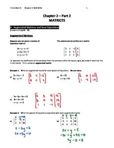
PHOTO 12: New HexFred rectifier diodes and R/C snubbers are installed in the existing Adcom footprints. This photo also shows the pre-regulators mounted on new heatsinks, along with three of the divider resistors. www.audioXpress.com
1203galo2290.qxd
10/17/2003
12:26 PM
ever, Victor Campos tells me that steel bottom plates were offered to customers who experienced hum problems in the phono preamp due to fact that aluminum does not provide sufficient shielding. See Photo 10, Part 1. • Fasten the filter-board assembly to the brackets with 4-40 hardware, and
Page 43
bolt the bracket/filter assembly to the side of the chassis using the hardware and mounting holes previously used to mount the original power transformer. The “L”-shaped mounting bracket fits right into the “L”shaped corner of the chassis. Route the leads under the main PC board. If you space everything as shown in Photo 10, the old transformer mounting holes will line up in the
PHOTO 13: Mounting brackets for the DC common-mode choke assembly, with long and short dimensions. The brackets are fabricated from 0.064 × ¹⁄₂″ brass stock.
center of the mounting bracket stock. When you are finished, there should be at least ¹⁄₈″ clearance between the filter choke and the main PC board. • You must interrupt the PC traces between the + and − rectifier outputs and the C905/C906 raw-DC filter capacitors by cutting two traces on the main PC board. The locations of the cut traces are shown in Photo 14. Make the cuts a good ¹⁄₄″ wide, and be sure that you remove all copper material. • Solder the leads from the filter choke to the PC board as shown in Photo 14 , trimming the leads to the required length. Here, and during the regulator installation later, you will need to scrape enough enamel off the PC trace to provide a good soldering surface. After scraping the enamel, be sure that the exposed copper is clean, and tin the surface with solder. Then, solder the lead to the prepared surface. • Photo 10 shows an insulator made with ¹⁄₁₆″, rubber-gasket material between the fuse-holder and the filterchoke assembly. There should be plenty of clearance between the
the authority on hi-fi DIY
Subscribe to eConnexion, a monthly email newsletter featuring the latest happenings at pcX - including great specials, clearance items & new product introductions. Also our online catalog is expanding quickly.
1-866-681-9602 www.partsconneXion.com Tel: 905-681-9602 Fax: 905-631-5777
[email protected] Visa, MasterCard, American Express (+2%), Paypal (+2%), BidPay, Money Order/Bank Draft/Cashier’s Check, Personal Check (after clearance) 2885 Sherwood Heights Drive, Unit #72, Oakville, Ontario, CANADA L6J 7H1 IMPORTANT NOTE: No “on-site/walk-in” business at this time... however, pick-up orders can be arranged by appointment only. Call for details.
audioXpress December 2003 43
1203galo2290.qxd
10/17/2003
12:26 PM
choke assembly and the fuse holder, but I suggest adding the insulator as a safety precaution. You can fasten the insulator to the bottom of the fuse holder with a nylon cable tie (Photo 10). The insulator should be long enough to overhang the fuse holder by about ³⁄₄″. The muting circuit does not have symmetrical current drain from the power supply. The current drains from the raw supply rails feeding the 78M15 and 79M15 regulators (IC901 and IC902) are 21mA from the positive rail and 18mA from the negative. This is only a difference of 3mA, but the choke won’t function as a true common-mode device if the currents through the two coils are mismatched. There’s enough of a difference in voltage drops across the two coils in the common-mode choke to produce a raw supply difference of about 1V between the positive and negative supplies. The easy solution is to pull another 3mA of current from the raw negative supply by adding to a shunt resistor:
Page 44
of most of these electrolytics. One of the goals of this project was to eliminate steel leads on passive components wherever possible, especially post-regulator. This is not possible to do with the improved regulator due to limitations in the PC board layout, but in the post-regulator it is quite feasible. The Nichicon and Mallory caps used to replace the Panasonic originals for local-supply bypassing have copper leads. These Nichicon electrolytics have also been designed specifically for audio applications, and perform extremely well. Walt Jung and I found that higher DC voltage ratings on electrolytic power-supply capacitors are sonically beneficial, so I have used what I believe is a good balance between adequate voltage and capacitance values, without exceeding the
available physical space. Some readers may wonder why I have not used the Black Gate caps, considered by many to be the best electrolytics available. The reason is that they are extremely expensive, and they will be a tight fit in the physical spaces available on the Adcom PC board. See Fig. 4. • Replace C905 and C906 with 4700µF, 80V DC Nichicon KG-Gold electrolytic capacitors. Observe polarity! • Replace C917, C918, C121, C122, C121B, C122B, C401, and C403 with 1000µF, 50V Nichicon KZ electrolytic capacitors. Observe polarity! • Replace C119, C120, C121A, C122A, C402, C404, C907, and C908 with 1.0µF, 50V Mallory 168-series film capacitors.
• Solder an 8.25k ½W resistor from the raw negative supply to ground. This is R905 in Fig. 2. This resistor was added after I took the photos. Solder it across C905 on the bottom of the PC board.
44 audioXpress 12/03
T7 Sense Screen T10 Sense GND Q902* LT1085CT
+26VDC
IN
3
OUT
T9 Sense
+20VDC
T2 Reg Out T6 T3 T20 GND
R9101** 1.0k
COM
+14VDC
C905* 4700uF
C907* 1uF
1 (ADJ) 2
-
-26VDC
IN
OUT
Q901* LT1033CT
3.65k
R9104**
3.65k
C918* 1000uF
T11 T13 T19 GND T14 Reg Out
3 -20VDC
T17 Sense
Rs+** 10
D911** 1N4003 Rs-** 10
-14VDC
Cs-** 0.01uF
T12 Unreg In
T18 Sense GND
Q901/Q902 Pin-Out O
* = New Value ** = New Part
T15 Sense Screen
Jung Improved Regulator (-)**
1 2 3
C121A* 1uF
+
C402* 1uF
C122A* 1uF
+
C120* 1uF
+
C119* 1uF
C121* 1000uF
+
+14V
C404* 1uF
C121B* 1000uF
C401* 1000uF
PC GND C122* 1000uF
-14V
D912** 1N4003
C917* 1000uF
R9103** 1.0k
COM
From Rectifier Neg Out
R9102**
-14VDC
PC Board GND
C908* 1uF
+
C906* 4700uF
+
+
1 (ADJ)
Cs+** 0.01uF
T5 Unreg In
2
PC GND +14VDC
From Rectifier Pos Out +
+
Before removing and replacing the Adcom power-supply regulators, replace all of the power-supply electrolytic capacitors and local film bypassing that affect the audio circuitry. Adcom used Panasonic TSNH-series electrolytic caps for raw-DC filtering (C905 and C906), and Panasonic HF-series electrolytics for local bypassing (C917, C918, C121, C122, C121B, C122B, C401 and C403). Panasonic film capacitors were used for high-frequency bypassing
Jung Improved Regulator (+)**
+
NEW ELECTROLYTICS
PHOTO 14: Two traces must be cut on the main PC board to insert the DC common-mode choke between the rectifiers and the raw-DC filter capacitors. The photo shows the locations of the cut traces, and the connections to the choke.
+
At this point, power up the preamp and check the raw- and regulated-supply voltages. The raw DC voltages at C905 and C906 will be around ±26V DC, and the regulated voltages still should be at ±17.5V DC. Put the covers on and listen to the preamp, if you like. Everything done so far should yield a noticeable sonic improvement.
C122B* 1000uF
C403* 1000uF
Chassis GND PHONO
LINE STAGE
LOCAL SUPPLY BYPASSING
www.audioXpress.com
TAPE OUT BUFFERS
FIGURE 4: Interconnection diagram for the pre-regulators and the main Jung Improved Regulators. New filter capacitors and local bypassing are also shown. A-2290-1
1203galo2290.qxd
10/17/2003
12:26 PM
Page 45
Power up the preamp and re-check the raw- and regulated-supply voltages. The Nichicon KG-Gold capacitors are the same height as the Panasonic TSNH caps, which means that they can actually touch the inside of the preamp’s metal cover. Although the tops of the original Panasonic capacitors were completely insulated, I found that repeated removal and replacement of the cover
began to wear through the plastic insulation on the capacitors. The Nichicon caps have exposed metal in the center, so it is imperative that the metal cover be insulated from these capacitors. I contact-cemented a 6″ square piece of ¹⁄₁₆″ gasket material, available at any hardware store, to the inside of the cover. Position the gasket material so that it is 1½″ from the rear edge of the cover, and 3⁷⁄₈″ from the left edge. An alternative to the gasket material is the tray from a CD jewel case, with the edges cut off with a band saw. This insulator is not an option! It is mandatory for safe and proper operation of the preamplifier!
PRE-REGULATOR INSTALLATION PHOTO 15: Three traces must be cut near the Q901 and Q902 footprints to facilitate installation of the pre-regulators. This photo was taken before the removal of the old Adcom regulator components.
Now you’re ready to remove the original Adcom power-supply regulators and install
the Jung Improved Regulators, complete with the floating pre-regulators shown in Fig. 4 of Walt’s 4/00 article. Fortunately, the Adcom PC layout allows the installation of the pre-regulators in the original regulator footprint by cutting three PC traces and adding one jumper. Note that you will replace only the main positive and negative regulators. The ±15V regulators that power the muting relaysIC901 and IC902 and associated componentsare retained. These regulators have no effect on the sound, so there’s no need to replace them (they were also used to power the headphone amplifier, now removed). Begin by removing all of the Adcom regulator components and cutting the traces: • Remove Q901, Q902, Q903, and Q904. Save the four mounting screws used for the Q901 and Q902 heatsinks. • Remove D903, D913, D914, and D915. • Remove R908, R909, R910, R911, and R912. • Remove C914. See Photo 15.
LANGREX SUPPLIES LTD
DISTRIBUTORS OF ELECTRONIC VALVES, TUBES & SEMICONDUCTORS AND I.C.S. 1 MAYO ROAD, CROYDON, SURREY, ENGLAND CR0 2QP FAX PHONE 24 HOUR EXPRESS MAIL ORDER SERVICE ON STOCK ITEMS 44-208-684-3056 44-208-684-1166 E-MAIL:
[email protected]
A SELECTION OF OUR STOCKS OF NEW ORIGINAL VALVES/TUBES MANY OTHER BRANDS AVAILABLE STANDARD TYPES ECC81 ECC82 ECC83 ECC83 ECC85 ECC88 ECC88 ECL82 ECL86 EF86 EF86 EL34 EL37 EL84 EL509 EL519 EZ80 EZ81 GZ32 GZ33/37 PL509 UCH81 UCL82
RFT RFT RFT EI RFT BRIMAR MULLARD MULLARD TUNGSRAM USSR MULLARD EI MULLARD USSR MULLARD EI MULLARD MULLARD MULLARD MULLARD MULLARD MULLARD MULLARD
AMERICAN TYPES 3.00 6.00 8.00 4.00 5.00 6.00 10.00 5.00 10.00 5.00 15.00 6.00 30.00 3.00 10.00 7.50 5.00 10.00 25.00 20.00 10.00 3.00 2.00
5R4GY 5U4GB 5Y3WGT 6BX7GT 6FQ7 6L6GC 6L6WGB 6SL7GT 6SN7GT 6V6GT 12AX7WA 12BH7 12BY7A 211/VT4C 807 5687WB 6072A 6080 6146B 6922 6973 7308 SV6550C
RCA SYLVANIA SYLVANIA GE EI SYLVANIA SYLVANIA USA USA BRIMAR SYLVANIA BRIMAR G.E. G.E. HYTRON ECG G.E. RCA G.E. E.C.G. RCA SYLVANIA SVETLANA
SPECIAL QUALITY TYPES 7.50 15.00 5.00 7.50 5.00 20.00 15.00 7.50 7.50 7.50 7.50 12.00 7.00 85.00 7.50 6.00 10.00 10.00 15.00 6.00 15.00 5.00 20.00
A2900/CV6091 E82CC E83CC E88CC G. PIN E188CC ECC81/6201 ECC81/CV4024 ECC81/M8162 ECC81/6201 G. PIN ECC82/CV4003 ECC82/M8136 ECC83/CV4004
G.E.C. SIEMENS TESLA TESLA MULLARD G.E. MULLARD MULLARD MULLARD MULLARD MULLARD MULLARD
17.50 7.50 7.50 8.50 20.00 5.00 6.00 7.50 10.00 15.00 17.50 40.00
SOCKETS B7G B9A OCTAL OCTAL LOCTAL
CHASSIS CHASSIS CHASSIS MAZDA B8G CHASSIS
0.60 1.00 1.00 2.00 2.50
SCREENING CANS ALL SIZES
1.00
MANY OTHER BRANDS AVAILABLE These are a selection from our stock of over 6,000 types. Please call or FAX for an immediate quotation on any types not listed. We are one of the largest distributors of valves in the UK. Same day dispatch. Visa/Mastercard acceptable. Air Post/ Packing (Please Enquire). Obsolete types are our specialty.
audioXpress December 2003 45
1203galo2290.qxd
10/17/2003
12:26 PM
Page 46
• Cut the three PC traces as shown in Photo 15. Be sure that you remove all copper material and that the PC board is completely clean when you are finished. (Note that Photo 15 was taken before the removal of the Adcom supply components).
Figure 4 shows the power-supply preregulator and main-regulator connections. I have set the pre-regulators at ±6V, which puts the input to the main regulators (the Jung Improved Regulators) at ±20V, half-way between the raw DC voltages of ±26V and the main-regulator outputs of ±14V. This ensures more-or-less equal heat dissipation by the pre-regulators and the pass transistors of the main regulators. With this scheme, the pre-regulators drop out of regulation with a line voltage of about 105V AC; the dropout point for the main regulators is considerably lower. Now you can install the pre-regulator components. I originally used the 1″ Adcom heatsinks for the pre-regulators, but they ran a bit warmer than I liked so I decided to replace them with 1½″ Wakefield 634-15ABP types (or Aavid 581102B00000). I admit that I am being conservative herethe original Adcom heatsinks are probably adequate, but I did not wish to take any chances on long-term reliability. You can use National’s LM317T and LM337T devices recommended by Walt Jung for the preregulators, but I prefer the Linear Technology LT1085CT and LT1033CT types for their lower dropout characteristics and higher dynamic current capability. Linear Technology’s website notes that the LT1033CT is not recommended for new designs, so they may be planning to discontinue this item. As long as it remains available from Digi-Key, I see no reason not to use it. If it does become unavailable, I suggest the LM317T/337T pair, or Linear Technology’s LT1086AT/LT337AT combo. I don’t recommend a “mix and match” approach to picking the + and − pre-regulators; always use a complementary pairLM317T/337T, LT1086AT/337AT, or LT1085CT/1033CT. See Photo 12. • If the heatsinks you purchased have mounting pins, remove them. This
46 audioXpress 12/03
PHOTO 16: Close-up of the pre-regulators, bottom view, showing the locations of R9104 and the jumper.
may take a bit of effort, because the pins are usually very tight. I suggest clamping the pin in a vise and twisting the heatsink back and forth until it comes loose. The Aavid type should not have pins. • Mount the Linear Technology LT1085CT and LT1033CT regulators on the new Wakefield heatsinks with ¹⁄₄″, 6-32 machine screws. You can use the original Adcom sil- PHOTO 17: The regulator-board bracket with its long and icone insulating pads short dimensions. The bracket is fabricated from a piece of to facilitate heat trans- 0.064 × ³⁄₄″ brass stock. fer, or use white thermal compound (my preference). tor assembly in the Q902 footprint. Don’t use clear silicone grease; real Use the old Adcom mounting screws thermal compound contains metal to secure the heatsinks to the PC oxide, necessary for efficient heat board, then solder the three regulator transfer. Although the Adcom pads leads to the board. are an electrical insulator, this is unnecessary since the heatsinks don’t You can mount three of the voltagemake electrical contact with any- divider resistors for the pre-regulators thing. Since the Aavid and Wakefield in existing PC holes on the component heatsinks are tapped for a 6-32 ma- side of the Adcom board. See Fig. 4 and chine screw, you can’t use insulating Photo 12. washers with the TO220 regulators • Install R9103 (1.0k) in the rear-most anyway. holes previously occupied by D913 • Install the LT1033CT negative-regulaand R910. This resistor will stand on tor assembly in the Q901 footprint. enduse sleeving on the longer lead. Use the old Adcom mounting screws to secure the heatsinks to the PC • Install R9101 (1.0k) in the holes previously occupied by D914. This resistor board, then solder the three regulator will stand on enduse sleeving on leads to the board. the longer lead. • Install the LT1085CT positive-regulawww.audioXpress.com
1203galo2290.qxd
10/17/2003
12:26 PM
• Install R9102 (3.65k) between the holes previously occupied by the collector (center pin) of Q904 and the forward-most hole previously occupied by R908. You should mount the remaining resistor, plus a jumper, on the bottom of the PC board (Photo 16).
Page 47
• Install R9104 (3.65k) between the pad occupied by J66 and the hole previously occupied by the center pin (collector) of Q903. J66 is not removed the resistor shares this PC pad with this jumper. Use clear sleeving over this resistor. • Install an insulated 16AWG jumper between the +26V raw supply trace scraping enough enamel off the PC trace to allow a good connection and the rearmost hole previously occupied by R912. This connects the raw-DC supply to the LT1085CT input (pin 3).
MAIN REGULATOR MOUNTING
PHOTO 18: Top view of the Jung Improved Regulators installed in the preamp. The mounting bracket sits tight against the brass support for the main PC board.
At this point you should assemble and test the Jung Improved Regulators. Follow the instructions in AE 4/00, plus the testing procedure in TAA 4/95, with a few clarifications. The heatsinks for each pass transistor should include a Digi-Key HA113-ND 2W extender along with the recommended HA112-ND. Use the AD825AR opamp for X1 and X2. I strongly recommend using a good SOIC-to-DIP adapter for mounting the AD825 on the 8-pin DIP footprint of the Didden PC boards,
The British specialists in tube amplifiers and pre-amplifier kits, loudspeaker kits and related publications Visit our informative website: www.worldaudiodesign.co.uk Enter our HD83 competition on-line
KiT88 integrated amplifier kit
300b PSE monobloc kit
Kel84 integrated amplifier kit
Series II modular pre-amplifier kit
World Audio Publishing Ltd. 12a Spring Gardens. Newport Pagnell. Milton Keynes. MK16 0EE. England
PHOTO 19: Bottom view of the Jung Improved Regulators. All connections are made to the bottom of the regulator PC boards.
tel/fax: 00 44 1908 218836 e-mail:
[email protected]
audioXpress December 2003 47
1203galo2290.qxd
10/17/2003
12:26 PM
rather than attempting to solder the AD825 to a header. The Aries adapter listed in the Jung parts list is fine, as is the Accutek Microcircuit #AK08D-NSO mentioned in the parts list for this article. Many aX readers may not be familiar with Accutek Microcircuit; they manufacture a sizable assortment of adapters for IC mounting. I haven’t found any need to implement the stability/RFI option described in Walt’s side-
Page 48
bar (AE 4/00, p. 16). Walt has found that the electrolytic capacitors in the regulators also benefit from higher voltage ratings, and the Panasonic HFQ series he originally recommended has been discontinued. At his suggestion, all of the 120µF/25V Panasonic HFQ electrolytic capacitors are replaced with 47µF/63V Nichicon UVR series. I suggest cleaning the Jung regulator boards with Caig CaiKleen
PHOTO 20: Large view of the main PC board showing connections to the Jung Improved Regulators.
48 audioXpress 12/03
www.audioXpress.com
TRP DG7S-6 spray when you are finished with the assembly and testing to remove all excess flux. CaiKleen TRP is a low-residue, citrus-based degreaser and flux remover, and my personal favorite for PC board cleaning. The Roederstein/Resista MK3 resistors have also been discontinued, though some dealers still have ample stocks. In the interest of eliminating magnetic materials wherever possible, Walt suggested replacing these with Vishay-Dale CMF Type RN60D, which is a military type. All Vishay-Dale RN60D resistors have solder-coated copper leads, and all of the ones I’ve received from Mouser have non-ferrous end caps. However, Vishay does not guarantee that these resistors will be entirely non-ferrous, and I have heard reports of some parts coming through with steel end caps. The “D” in the RN60 designator refers to the temperature coefficent, which is a mil spec of +200/−500ppm. But, Vishay claims that they supply ±100ppm parts for characteristic “D.” Since we are using 1/2W resistors where, for the most part, 1/4W types would be adequate, a temperature coefficient of ±100ppm shouldn’t be a problem. Mouser lists the RN60D resistors as 1/4W, but that is the military rating. For non-military applications, these are 1/2W resistors. Holsworthy Electronics, makers of the highly regarded Holco non-ferrous resistors, merged with Meggitt Electronics a while back, and Tyco has subsequently taken over Meggitt/Holsworthy. The Holco resistors have been made with steel end caps since the merger with Meggitt. You can easily identify the new resistors, since they are completely cylindrical in shape, in contrast to the “dog-bone” style of the old all-copper Holcos. Holcos are no longer the perfectionist audio resistor that they once were. Once you have built the Improved Regulators, it is imperative that you test them as I outlined in TAA 4/95. You need to be absolutely sure that the regulators are working properly before installing them in the preamp. Use the remote sense de-coupling that I described in Part 4 of the 1995 regulator series. The 0.01µF capacitors, Cs+ and Cs−, are soldered to the bottom
1203galo2290.qxd
10/17/2003
12:26 PM
side of the regulator boards. These should be Mallory 168-series, as shown in the parts list. Installation of the 10Ω resistors, Rs+ and Rs−, will be described later. Mount the regulator boards on a bracket made from 0.064 × ³⁄₄″ brass stock. Photo 17 shows the bracket dimensions and locations of the mounting holes. You must drill four holes to accommodate the Jung regulator boards. Note that these four mounting holes are not centered on the regulator bracket, but rather are offset so the positive regulator mounting holes are close to the edge of the bracket. This is necessary in order to make connections to the bottom side (underside) of the positive regulator board. Photo 18 is the top view of the assembled regulator boards, mounted on the brass bracket. Use ⁵⁄₈″ 4−40 machine screws, ¹⁄₄″ nylon spacers, lock washers, and nuts to mount the regulator boards on the brackets. The bracket sits against the main brass chassis support (Photo 18). A single ¹⁄₂″ 6-32 machine screw, lock washer, and nut holds the bracket in place, using an existing hole in the preamp chassis side rail. When installed, the right-angle bend in the brass regulator board bracket will be flush with the top edge of the chassis side rail, and the cover will fit on the preamp with at least ¹⁄₂″ clearance between the pass transistor heatsinks and the preamp’s metal cover.
WIRING THE REGULATOR The reverse-polarity protection diodes D911 and D912 in Fig. 4 are also shown in the Adcom schematic and PC board layout. However, I have never actually seen these diodes in a GFP-565 preamp, and none of the production Adcom PC boards I’ve seen have a footprint for them. I’ve designated these as new parts in Fig. 4. I suggest putting them in if your preamp does not have them. • Install D911 and D912 as shown in Fig. 4. Use two of the 1N4003 diodes removed when you replaced the rectifier bridge. You can solder these anywhere along the main power-supply bususe the pads where the brass rails are soldered in place. Carefully observe diode polarity.
Page 49
Accuracy, Stability, Repeatability Will your microphones be accurate tomorrow?
Next Week? Next Year? After baking them in the car???
ACO Pacific Microphones will! Manufacturered to meet IEC, ANSI and ASA standards. Stainless and Titanium Diaphragms, Quartz insulators Aged at 150°°C. Try that with a “calibrated”consumer electret mic!
ACO Pacific, Inc.
2604 Read Ave., Belmont, CA 94002 Tel: (650) 595-8588 FAX: (650) 591-2891 e-mail
[email protected]
ACOustics Begins With ACO™
AUDIO TRANSFORMERS AMERICA’S PREMIER COIL WINDER Engineering • Rewinding • Prototypes
McINTOSH - MARANTZ - HARMAN-KARDON WESTERN ELECTRIC - TRIAD - ACROSOUND FISHER - CHICAGO - STANCOR - DYNACO LANGEVIN - PEERLESS - FENDER - MARSHALL ELECTROSTATIC SPEAKER TRANSFORMERS Williamson Amplifier Transformer Specialist WE DESIGN AND BUILD TRANSFORMERS FOR ANY POWER AMPLIFIER TUBE PHONE: [414] 774-6625
FAX: [414] 774-4425
AUDIO TRANSFORMERS 185 NORTH 85th STREET WAUWATOSA, WI 53226-4601
E-mail:
[email protected] NO CATALOG CUSTOM WORK audioXpress December 2003 49
1203galo2290.qxd
10/17/2003
12:26 PM
Make all connections to the Jung/Didden regulator boards to the pads on the bottom side of the board (Photo 19). I used 14AWG, stranded wire for the connections from the preregulators to the main-regulator inputs, and double-runs of 16AWG insulated solid bus wire for the main-regulator output and ground connections. To make the connections to the main PC board, prepare soldering surfaces on the PC traces as necessary. See Photos 19 and 20, and Fig. 4. • Solder 14AWG, stranded wires between the pre-regulator outputs on the main PC board and the input pads on the main-regulator boards. The output terminal on the positive LT1085CT pre-regulator is pin 2. The output terminal on the negative LT1033CT pre-regulator is pin 3. • Connect the ground pads of both regulators to the ground bus on the main PC board. Use double-runs of 16AWG insulated, solid bus-wire for each regulator. As Photo 20 shows, there is a large ground area on the Adcom PC board which will provide
Page 50
plenty of space for soldering the four solid wires (two in parallel for each regulator). • Connect the negative output of the main regulator to the negative bus on the Adcom PC board. Use a doublerun of 16AWG insulated, solid buswire. • Similarly, connect the positive output of the main regulator to the positive bus on the Adcom PC board. All that remains is to connect the remote sense lines for the main regula-
tors (Fig. 4 and Photos 19, 20, and 21). The remote sense lines require a twoconductor shielded cable, allowing a ground connection on both ends, with a floating shield at the sense point. I suggest D.H. Labs Silver Sonic BL-1 interconnect cable for these connections. The remote sense will give best performance if the sense point is close to the load. Since the phono preamp and line stage are physically separated, I decided to make the sense point roughly equidistant from the two circuits, just
PARTS LIST Rectifiers and Filter Caps: (4) International Rectifier HFA08TB60 HexFred Diodes, Digi-Key HFA08TB60-ND (D907-D910) (4) 47.5Ω, 1/2W resistor, Vishay-Dale CMF Type RN60, Mouser 71-RN60D-F 47.5; or Roederstein Resista MK3 (R901-R904) (4) 0.47µF, 100VDC capacitor, Xicon MEB, Mouser 1430-1474; or Panasonic V-series, Digi-Key P4733-ND (C901C904) Panasonic V-series Line Filter, 56mH, 1.1A, Digi-Key PLK1017-(L001) (1) 8.25k, 1/2W resistor, Vishay-Dale CMF Type RN60, Mouser 71-RN60D-F-8.25k or Roederstein Resista MK3 (R905) (2) 4700µF, 80VDC Nichicon KG-Gold, Michael Percy Audio (C905, C906) (8) 1000µF, 50VDC Nichicon KZ, Michael Percy Audio (C917, C918, C121, C122, C121B, C122B, C401, C403) (8) 1.0µF, 50VDC Mallory 168-series, Newark 89F1692 (C119, C120, C121A, C122A, C402, C404, C907, C908) (2) 1N4003 Diodes (use discarded Adcom rectifiers) (D911, D912) Miscellaneous ³⁄₈″ heat-shrink tubing for rectifiers (Radio Shack) Prototyping Board, Circuit Specialists IF-RFB 0.064 x ¹⁄₂″ brass stock (local hardware or hobby store) ¹⁄₁₆″ rubber gasket material (local hardware store) Power Supply Regulators: Linear Technology LT1085CT 3A, 3-terminal positive regulator, Digi-Key LT1085CT-ND (Q902) Linear Technology LT1033CT 3A, 3-terminal negative regulator, Digi-Key LT1033CT-ND (Q901) Wakefield 634-15ABP 1¹⁄₂″ Heat Sink, Newark 91F3674 or Aavid 581102B00000, Digi-Key HS303-ND (2) 1.0k, 1/2W 1% Metal-Film Resistor (R9101, R9103)* (2) 3.65k, 1/2W 1% Metal-Film Resistor (R9102, R9104)* (2) 10Ω, 1/2W 1% Metal-Film Resistor (Rs+, Rs−)* *Suitable resistors include Vishay-Dale CMF Type RN60, Mouser 71-RN60D F-Value; or Roederstein Resista MK-3 (Discontinued, but many values still available from Michael Percy Audio). (2) 0.01µF, 100VDC Mallory 168-series, Newark 46F3689 (Cs+, Cs−) (1 ±Pair) Jung Improved Positive/Negative Regulators built on Didden PC Board. All parts are as per Walt Jung’s 4/2002 Audio Electronics article, P.11, with the following changes/clarifications: All 120µF, 25V Panasonic HFQ capacitors are changed to Nichicon UVR-series, 47µF, 63V, Mouser 647UVR1J470MEA All resistors may be changed to Vishay-Dale CMF Type RN60D, Mouser 71-RN60D-F-Value Use Digi-Key HS113-ND 2W Heat Sink Extenders along with the recommended HS112-ND Use the AD825AR Op-Amp for X1 and X2, Analog Devices AD825AR, Newark 83F3403 Use Aries 8-pin SOIC/DIP Adapters for the AD825AR Op-Amp, Digi-Key A724-ND, or Accutek Microcircuit AK08D300-NSO Miscellaneous Chemtronics Heat Sink Grease, Digi-Key CT40-5-ND 0.064 × ³⁄₄″ brass stock (local hardware or hobby store) ¹⁄₄″ nylon spacers for #4 machine screw, Digi-Key 876K-ND D.H. Labs BL-1 Cable 16 AWG insulated solid bus wire, Digi-Key A3057B-100-ND 14AWG insulated stranded wire Caig CiaKleen TRP DG7S-6 Cleaner, MCM Electronics 200-095 or Caig Laboratories DG7S-6 Nylon Cable Ties (Radio Shack)
50 audioXpress 12/03
www.audioXpress.com
1203galo2290.qxd
10/17/2003
12:26 PM
Page 51
PHOTO 21: Close-up of the remote sense connections to the main power-supply buses, through the 10Ω de-coupling resistors. The 16AWG replacement jumpers for the supply bus are on the left.
ahead of where the main-supply buses branch off to the line stage. This is also right next to the 16AWG, solid jumper wires installed in Part 1. Photo 21 shows this location. • Install a remote sense cable for the negative supply using D.H. Labs BL-1 cable. Solder the shield drain wire to the T15 sense screen pad on the Jung regulator board. Use sleeving on the drain wire. Solder the black ground wire to the T18 sense GND pad. Both wires should go through to the top side of the board where they are also soldered to the regulator-board ground plane. These are the only wires that also require soldering to the component side of the regulator board. Solder the red wire to the T17 sense pad. • Photo 21 shows a close-up of the remote sense connections to the mainsupply bus, through the 10Ω decoupling resistors. The drain wire of the BL-1 cable is not connected on this end, so the shield floats. Solder the black wire to the ground bus on the Adcom PC board. You can solder the red wire to the 10Ω resistor by bending a hook in the wire and the resistor lead, crimping them together, and then soldering. Use plenty of clear sleeving over everything. Solder the resistor to one of the pads supporting the brass supply-bus rails. • Install a remote sense cable for the positive supply using D.H. Labs BL-1 cable. Solder the shield drain-wire to the T7 sense screen pad on the Jung regulator board. Use sleeving on the drain wire. Solder the black ground wire to the T10 sense GND pad. Both wires should go through to the top side of the board where they are also soldered to the regulator board
ground plane. These are the only wires that also require soldering to the component side of the regulator board. Solder the red wire to the T9 sense pad. • Connect the BL-1 positive remote sense cable and 10Ω decoupling resistor following the procedure outlined previously for the negative supply. • Use some small nylon cable ties to bundle the wiring neatly (Photos 19, 20 and 21). Check all wiring very carefully against the Fig. 4 schematic diagram and the photographs. When you are absolutely sure that all wiring is correct, connect the outboard transformer to the preamp and turn the power on. Use a variable AC transformer if you have onemonitor the main supply rails and make sure that the positive and negative supplies are headed in the right direction as you raise the line voltage from zero to 117V AC. Check all supply voltages shown in Fig. 4. The raw-DC voltages should be ±26V DC. There should be ±20V DC at the input terminals to the main Jung regulator boards (T5+ and T12−). There should also be ±14V at the main-regulator outputs and on the main-supply buses (or the brass supply-bus rails) on the Adcom PC board. You should also use an oscilloscope to check for oscillations on the pre-regulator outputs and the main-supply rails. I have built three of these preamps and have not experienced even a hint of supply instability. Clean the entire Adcom PC board with Caig CaiKleen TRP to remove all excess flux. Part 3 will describe an entirely new line stage. In the meantime, enjoy the sonic benefits of the improved power supply in your GFP-565 preamplifier. ❖
Thousands of electronic parts available online
www.allelectronics.com Ultra-Small 12 Vdc Latching Relay Aromat # TW2E-L-12V. Miniature single coil latching relay. 12 Vdc, 1440 ohm polarized coil. DPDT contacts rated 2 Amps. Body size: 0.58” x 0.28” x 0.427” high. PC pins. UL, CSA. CAT# RLY-87 10 for $1.10 each 100 for 85¢ each each
1
$ 25
Red-Green-Blue Flasher Standard clear T-1 3/4, 5mm package. This tri-color LED sequentially flashes each color quickly for about 5 seconds, then slowly fades the colors in and out over the next 60 seconds. Other colors are created by the mixing of the three main colors. 3.5 Vdc @ 40mA. CAT # LED-95
3
$ 75 each
10 for $3.50 each 100 for $3.00 each
256 X 64 Graphic LCD Panel Epson # EG2404Y-AR Module size: 7” x 2.74” x 0.4”. Viewing area: 5.47” x 1.5”. Includes hook-up diagram.
CAT # LCD-92
12 00
$
each
5” X 1” Electroluminescent Strip Ivory in off-state. Glows green when energized by 120 Vac or inverter. For backlighting control panels, special-effects lighting, models etc. Solderable pins extend 0.2" beyond end of panel. CAT# EL-5
3
$ 50 each
20 for $3.25 each 100 for $2.50 each
ORDER TOLL FREE
1-800-826-5432 CHARGE ORDERS to Visa, Mastercard, American Express or Discover TERMS: NO MINIMUM ORDER. Shipping and handling for the 48 continental U.S.A. $6.00 per order. All others including AK, HI, PR or Canada must pay full shipping. All orders delivered in CALIFORNIA must include local state sales tax. Quantities Limited. NO COD. Prices subject to change without notice. WRITE
CALL, FAX or E-MAIL for our FREE
96 Page CATALOGA.
Outside the U.S. send $3.00 postage.
MAIL ORDERS TO:
ALL ELECTRONICS CORPORATION P.O. Box 567 Van Nuys, CA 91408 FAX (818)781-2653
e-mail
[email protected]
audioXpress December 2003 51