AC-XX-DH Downhole Accelerometer Installation Instructions
Company:
GeoSIG Ltd
Author:
Serge Rudaz
Checked:
Christoph Kündig
Approved:
Johannes Grob
Level:
Customer
Distribution:
GeoSIG Ltd., Customers
GS_AC-xx-DH_Installation_Instructions_V04.doc/06.06.2014 AC-xx-DH Downhole Accelerometer
Document Revision Version
Description
0
Initial document
1
Revised according to new housing
2
Revised as a generic document for AC-23-DH and AC-63-DH sensors
3
Revised as a generic document for AC-xx-DH sensors
4
Revised with new logo and address
Page 2 / 17
GS_AC-xx-DH_Installation_Instructions_V04.doc/06.06.2014 AC-xx-DH Downhole Accelerometer
Page 3 / 17
TABLE OF CONTENTS 1.
INTRODUCTION .................................................................................................................................... 4
2.
INSTALLATION PROCESS................................................................................................................... 4 2.1.
PREPARATION ...................................................................................................................................... 4
2.2.
SENSOR INSTALLATION ......................................................................................................................... 5
3.
CONFIGURATION INSIDE THE DRILLED HOLE: ............................................................................... 7 3.1.
CASING INSTALLATION (PVC OR STEEL)................................................................................................. 7
3.2.
INCLINOMETER TUBE INSERTION ............................................................................................................. 8
3.3.
INSERTION OF THE SENSOR .................................................................................................................... 9
4.
HOLE SPECIFICATIONS .................................................................................................................... 10
5.
INCLINOMETER TUBE SPECIFICATION........................................................................................... 10
6.
TUBE ASSEMBLY, DETAILED PROCEDURE ................................................................................... 11 6.1.
ACCESSORIES .................................................................................................................................... 11
6.2.
CASING ASSEMBLY ............................................................................................................................. 12
6.2.1.
Requested material ....................................................................................................................... 13
6.2.2.
Preliminary .................................................................................................................................... 14
6.2.3.
Tubes-coupling assembling........................................................................................................... 15
6.3. 6.3.1.
INCLINOMETER CASING INSTALLATION .................................................................................................. 16 Borehole installation ...................................................................................................................... 16
6.4.
GROUTING .......................................................................................................................................... 17
6.5.
QUANTITIES ........................................................................................................................................ 17
GS_AC-xx-DH_Installation_Instructions_V04.doc/06.06.2014 AC-xx-DH Downhole Accelerometer
Page 4 / 17
1. Introduction This document describes the various steps needed for the installation of any of the GeoSIG AC-xx-DH series downhole accelerometers, including the installation of the inclinometer tubes and gives some guideline for the hole drilling. Such installation procedure / instructions need always to be reviewed according to local situation and must be used only as guidelines.
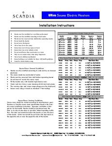
2. Installation process The basic installation principle looks like: Surface Borehole with or without casing
Soft material
Sand Sand CABLE Inclinometer tube
SENSOR Hard rock
Concrete Concrete Sand
GUIDE
Sand
Figure 1, Installation overview Please refer to the specific sensor manual for details about the sensor itself. Typical installation flow process is the following:
2.1. Preparation •
Access formality to the site (if required)
•
Drawing of site implementation, including cable length.
•
Preparation of the location of any surface sensors.
•
Installation of recording system (without routing cables going to down-hole sensor).
•
Hole drilling and tubing of hole.
•
Verification of hole deviation. The maximum deviation for sensor operation must remain within ±9°. Preferably, it should be ±3°.
GS_AC-xx-DH_Installation_Instructions_V04.doc/06.06.2014 AC-xx-DH Downhole Accelerometer
•
Page 5 / 17
Trench for down-hole sensor cables. Under-ground routing is preferred. Steel tubes could be directly installed under ground and the cable later routed. Ideally a steel wire should be inserted the whole tubes to simplify later the cable routing.
If the hole is equipped with cemented tubing, one week delay should be inserted here. If not, the next step should be executed as soon as possible to avoid any stone or other material to fall into the hole. It is highly important that the cementation at the bottom of hole is as good as possible to insure a good coupling near the level of the sensor. So injection should be performed first from the bottom. An injection plastic tube should be routed along the casing when it is inserted in the hole. If the injection cannot be fully performed from the bottom, the rest of injection should be done from the top. If possible, the cementation should be verified in the next 24 hours using ultrasonic measurement equipment or measuring the temperature profile in the hole. For both methods, water must be present in the hole. •
On site assembly of the inclinometer tube sections and insertion in the hole.
•
The first section must have a bottom cap (see drawing on next pages).
•
Each section must have a watertight assembly to the next section using silicon and adhesive tape. Watertight is important to avoid sediments coming into the tube.
•
The inclinometer tube must be filled with water to have positive pressure inside the inclinometer and reduce amount of incoming sediment in the tube. The water level must be higher than the level of water in the hole.
•
Cementation of the inclinometer tubes in the hole.
•
Verification of the cementation and wait at least one week before installing the sensor.
It is highly important that the cementation at the bottom of hole is as good as possible to insure a good coupling near the level of the sensor. So injection should be performed first from the bottom. An injection plastic tube should be routed along the casing when it is inserted in the hole. If the injection cannot be fully performed from the bottom, the rest of injection should be done from the top. If possible, the cementation should be verified in the next 24 hours using ultrasonic measurement equipment or measuring the temperature profile in the hole. For both methods, water must be present in the hole.
2.2. Sensor installation •
Sensor assembly (torpedo and guiding wheels).
•
Orientation of the sensor torpedo, the guiding wheels and the inclinometer tube.
•
Sensor insertion in the tube. If needed (depending on the level of water in the tube), additional weight must be fixed bellow the sensor. This will be noticed as a must if the cable becomes too “soft”.
•
Fixation of the sensor junction box at top of hole or nearby.
•
Electrical connection of the cable coming from the hole to any junction box.
It is not recommended to perform the cementation of the sensor at this moment. The whole installation must be finished and the system must run for some weeks and show correct operation before the final cementation of the sensor inside the hole is performed.
GS_AC-xx-DH_Installation_Instructions_V04.doc/06.06.2014 AC-xx-DH Downhole Accelerometer
Page 6 / 17
•
Routing of cables from recording system to the sensor junction boxes.
•
Connection of the cables to sensor junction boxes.
•
Sensor test using the recording system.
•
Whole system test.
•
Test period for the system. A continuous monitoring of the system must be implemented and all recorders must be verified. Especially, periodically some noise and sensor test measurements must be performed and verified. Of coarse as the sensors are not cemented, there could some records generated by movement of the cables along in the hole.
•
Final cementation of the sensors in the inclinometer tube.
Note: On site, a temporary AC power source must be present for the installation duration (if no permanent AC power is present). Please refer to the next sections to have more details about inclinometer installation and cementation (grouting).
GS_AC-xx-DH_Installation_Instructions_V04.doc/06.06.2014 AC-xx-DH Downhole Accelerometer
Page 7 / 17
3. Configuration inside the drilled hole: 3.1. Casing installation (PVC or steel) Note: Don’t scale the drawing. 12 cm Surface level
Drilling depth
Casing
Internal free diameter at least 12 cm
Tubing cementation
Cap
GS_AC-xx-DH_Installation_Instructions_V04.doc/06.06.2014 AC-xx-DH Downhole Accelerometer
Page 8 / 17
3.2. Inclinometer tube insertion Note: The drawing has no scale and the number of sections is only an example.
3 meters
Inclinometer tube section, 3 meters length
30 cm
Cementation
Coupling element Watertight by using adhesive tape and silicon. Fixation using "pop" rivet.
Bottom cap
GS_AC-xx-DH_Installation_Instructions_V04.doc/06.06.2014 AC-xx-DH Downhole Accelerometer
Page 9 / 17
3.3. Insertion of the sensor Note: The drawing has no scale and the number of sections is only an example.
About 50 cm
Water level above the sensor, maximum 50 meters.
About 70 cm + 100 cm for add. weight
About 300 cm
50 m maximum
Cable
Cementation of sensor. At least 1 meter above the sensor.
AC-xx-DH sensor torpedo, diameter 5 cm.
Guiding system
Sand (50 cm)
Note: It is recommended that at installation, the water level above the sensor is no more than 50 meters to insure that during the operation life of the installation the real water level will not exceed the 100 meters limit allowed for the sensor.
GS_AC-xx-DH_Installation_Instructions_V04.doc/06.06.2014 AC-xx-DH Downhole Accelerometer
Page 10 / 17
4. Hole specifications The hole must either have casing (steel or PVC) or insurance given that no ground material will fall in the hole before the inclinometer and that the inclinometer tube can be later inserted. If tubing is of PVC type, some water must be in the hole to sustain water pressure at bottom. Otherwise, there is the risk that the case breaks. For drilling depth of more than 30 meters, the drill diameter must be at least 12 cm to allow the inclinometer tube to enter the hole even if the hole has some deviation. Bellow 30 meters, 10 cm is sufficient. In case of use of the bottom valve the minimum diameter has to be 10 cm. In case of external grouting it has to be considered the dimension of the grouting tubes. The deviation of the hole must remain within the following specifications: •
The deviation drift must remain bellow ±1° / 3 meters
•
The deviation at sensor location should be within ±3°, the maximum operation position for the sensor is ±9° from vertical.
5. Inclinometer tube specification The dimensions of the inclinometer tubes are:
INCLINOMETRIC CASING (3 m section) A Inner diameter 76.1 mm
COUPLING ELEMENT A Inner diameter
81.0 mm
B
Groove outer diameter
86.4 mm
B
Outer diameter
92.0 mm
C
Thickness
2.2 ±0.1 mm
C
Thickness
2.2 mm
D
Groove inner diameter
82.0 mm
D
Groove inner diameter
87.6 mm
Length
3 meters
Length
300 mm
Weight
1.4 Kg/m
Weight
0.5 kg
Borehole diameter
> 100 mm
GS_AC-xx-DH_Installation_Instructions_V04.doc/06.06.2014 AC-xx-DH Downhole Accelerometer
Page 11 / 17
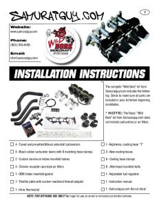
6. Tube assembly, detailed procedure 6.1. Accessories The following accessories can be extra ordered, they are not part of standard delivery.
Figure 2, Accessories Follows the complete list of inclinometer casing accessories (see Figure 2): •
Lockable top cap: a lockable protective cap, equipped with reference mark for topographical surveying. In case of in place inclinometer it is used to suspend the instrument. As an alternative, a simple cap can be supplied.
•
Pulley and cable stop: the pulley and cable stop is a device for easier handling of cable and probe during measurement. It is equipped with a connecting system designed to be compatible with lockable top cap.
•
Casing clamp: the casing clamp is a device used during the installation of the casing in vertical borehole. The main purpose of the casing clamp is to hold the casing string during the tube assembling.
•
Bottom grout valve: the grout valve is a standard accessory installed at the bottom of the casing and used during grouting procedure. It consists of a male quick joint coupling connected to a perforated tube jacketed by an expandable rubber membrane. The membrane acts as an unidirectional valve that, under injection pressure, permits to the grouting mix to flow outside.
•
Removable injection valve: the removable injection valve is the mating valve of the bottom one. It is mounted on a string of pipes or on the drilling rods, lowered inside the tube until it is connected with the mating bottom grout valve. At the end of the grouting operations the injection valve is removed from the grouting valve simply pulling up.
•
Bottom cap: as an alternative to the bottom grout valve. It prevents inflow of material inside the casing (not shown on figure).
GS_AC-xx-DH_Installation_Instructions_V04.doc/06.06.2014 AC-xx-DH Downhole Accelerometer
•
Page 12 / 17
Casing assembly kit: it includes the requested material to assemble 100 meters of casing (see Figure 3): o
Pop rivets and tool.
o
Sealing and adhesive tape
o
Adhesive compound.
o
Drilling tool.
Figure 3, Mounting kit
6.2. Casing assembly The procedure to obtain a satisfactory installation is explained in the following. Expert users can behave in different ways if they prefer. Anyway the main points have to be respected: •
A well done borehole (particularly regards of the verticality);
•
A correct sealing on the couplings;
•
Twist of the casing has to be avoided;
•
A well done grouting to ensure that the tube follows the deformation of the adjacent soil or structure.
The inclinometer casing can be entirely assembled and mounted on site at the time of insertion in the borehole. The minimum hole diameter (inside diameter of temporary lining) is function of the type of tube used specially the diameter at connection couplings and type of grouting method used (with or without bottom injection valve). To obtain meaningful/ results it is requested that the bottom of the column is placed inside the bedrock for some meters.
GS_AC-xx-DH_Installation_Instructions_V04.doc/06.06.2014 AC-xx-DH Downhole Accelerometer
6.2.1. Requested material The following tools and materials are needed: •
Hand drill or battery drill
•
Pop rivet gun
•
Rivets
•
Sealing tape or compound
•
Adhesive tape
•
Broad knife
•
Deepmeter
•
Clamps for tube locking
•
Hacksaw
•
Pieces of rebar as ballast
Page 13 / 17
GS_AC-xx-DH_Installation_Instructions_V04.doc/06.06.2014 AC-xx-DH Downhole Accelerometer
Page 14 / 17
6.2.2. Preliminary Mounting grouting bottom valve or cap onto inclinometer casing.
The steps for fixing the bottom cap are: 1. Put some sealant on the cap. 2. Fit the cap to the casing until ends are butted. 3. Drill four through-holes at 90 degrees intervals, away from ribs and rivet them. 4. Seal the cap to the crop-end section by sealant tape. If a bottom valve has to be used, the assembling procedure shall be exactly the same as the one described here (see Figure 4): •
Put adhesive and sealing compound on top of the grouting bottom valve.
•
Insert the grouting bottom valve into the casing.
•
Drill two holes through casing wall and grouting bottom valve.
•
Rivet the two holes.
Figure 4, Optional injection valve mounting
GS_AC-xx-DH_Installation_Instructions_V04.doc/06.06.2014 AC-xx-DH Downhole Accelerometer
Page 15 / 17
6.2.3. Tubes-coupling assembling Assembly is done at field before installation, for saving working time, however it is suggested to preassemble one section to its coupling, or even two sections to one interposed coupling and one coupling.
or
Follow the listed steps for connecting the ribbed tube section to the coupling as shown in Figure 5: 1. Put some sealant on one section end for a length corresponding to half the coupling. 2. Insert the coupling by half its length on the prepared tube crop end. 3. Couplings have no holes, so casing and coupling have to be drilled together in position. 4. Wrap the riveted coupling and the crop end section by adhesive sealant tape. For mounting a second tube section to the coupling follow the same sequence just described. By first, sealant must be spread on the end to be inserted into the coupling, then slip in the section until it matches to the previously assembled one. To mount the coupling on the flush tube, follow the instructions above. Take care during the insertion of the coupling that internal male reference element fit with the corresponding female reference located on the top of the casing section. Avoid dirtying inside surface by sealant. Allow the compound to harden for a few minutes before dipping the joint into the borehole water, for a good hardening of sealant. We suggest to use supplied sealing tape because after it has been wrapped on the joint coupling casing (pressing and shaping it for obtaining a good adherence) it provide an immediate perfect sealing of the casing string.
Figure 5, Coupling fixation
GS_AC-xx-DH_Installation_Instructions_V04.doc/06.06.2014 AC-xx-DH Downhole Accelerometer
Page 16 / 17
6.3. Inclinometer casing installation
(1) Insert first element with cap or valve (2) Clamp the section
(3) Insert next section
(5) Lift down the tube in the hole
(4) Seal and rivet the section
Repeat steps (2) – (5) until all sections are inserted. If the drilled hole is longer than the tube, be sure to have prepared a solution for the fixation of the tube at the top.
6.3.1. Borehole installation If temporary drilling casings are used, proceed as follows once the boring is completed, and after inclinometer tube length has been determined: 1. Check if drilling casings are not blocked into borehole by lifting and re-lowering them. 2. Check if borehole is clean down to the depth required for installation, including the ballast chamber, and eventual check the borehole bottom stability by means of the depth-meter. 3. Insert the first inclinometer section with cap or bottom valve, and with eventual ballast hanging beneath. If the bottom cap is used, grouting shall be injected by a separate flexible hose. At the contrary, if bottom valve is used, grouting shall be accomplished from inside the tubing by a quick joint mounted on rods. It is important to keep the same arrangement of grooves throughout all installation of the casing in order to avoid torsional stresses. Clamp shall be used to avoid damage of casing, by dents or inks. 4. Connect the first coupling (if not already pre-assembled) following the procedure described above. 5. Assemble the second section (if not already preassembled) and held it by a second clamp. 6. Remove the first clamp and lower the second crop-end until the second clamp is resting on the drilling casing top. If there is water in the hole, fill the crop-ends with water as they are inserted, in order to balance buoyancy in the case the first tube section was not ballasted. 7. Continue adding tube sections and couplings until the string has been completed.
GS_AC-xx-DH_Installation_Instructions_V04.doc/06.06.2014 AC-xx-DH Downhole Accelerometer
Page 17 / 17
6.4. Grouting When the whole casing has been mounted, and all the string rest at borehole, the cavity between borehole and the inclinometer casing can be grouted. The grouting procedure using the bottom valve is specified here under: 1. Insert into the casing the string of injecting tubes equipped with a quick joint valve (that shall be recovered) to connect to the bottom valve. 2. Check the connection. 3. Inject a grouting mix 100 liters of water, 50 kg of cement, 10 kg of bentonite. The bentonite percentage may be increased or reduced according to the consistency of the examined soil). Use low pressure and low flow until the undiluted mix flows back to ground surface. 4. Snap off the grouting line connection and recover the valve. 5. Pump through the injection rods string (having the bottom rod 0,5 m from the hole bottom), clean water up to when the return water is clean to flush away the grouting mix that was left inside the injection tube. In this way it is supposed that the tube and the grooves specifically are clean. In case the drill string cannot be left down for the soil friction, these operations can be done after the drill string has been recovered. 6. Recovery the string of the rods. 7. Keep the level of the grouting mix at the field level. 8. Cut at 30 cm from the ground level the inclinometer casing in excess. The cut has to be plain and well done. This operation, if can help the works, can be made before point 7. 9. By measuring the cut length, determine the length of the string. 10. Complete the installation by mounting on the top a plastic cap or if required the lockable top cap. 11. Mark the four grooves according to numbers 1-2-3-4 clockwise. The numbers are of basic importance for the readings to be done and have to remain the same for all the life of the tube. Generally we suggest having groove n° 1 in the direction of the foreseen mass movement. 12. Take with a compass the bearing of groove n. 1 referred to Nord and keep it on the reports. 13. Wait at least 1 week before sensor installation in the inclinometer tube.
6.5. Quantities External hole or casing diameter
Volume between hole and tube
cm
dm / meter
10
4
12
7.5
15
14
3
Volume inside tube 3
dm / meter
5
It is always needed to have extra reserve for cementation of the tube inside the drilled hole as there could be some cavities that could required some extra meter cubic !!! Note : The water level inside the tube should not be more than 50 meters at installation. This should insure a security margin in case of change in the ground water level of heavy rains.