Proceedings of the 28th Annual Hawaii International Conference on System Sciences - 1995
A Simulation-Based Comparison of Two Reflective Memory Approaches Milan JovanoviC
Milo Tom&viC*
Departmentof Computer Engineering School of Electrical Engineering University of Belgrade POB 816 11000Belgrade Yugoslavia
Veljko MilutinoviC (*)Department of ComputerEngineering Institute Mihajlo Pupin University of Belgrade POB 15 11000 Belgrade Yugoslavia
Abstract
Hardware implementations are also more f%equentlyfound in the commercial systems. These techniques are founded on the well-studied principles of coherence maintenance of private caches in shared-memory multiprocessor systems [Tom94a,Tom94b]. A prominent example of the hardware-implemented DSM mechsnismsis the reflective memory concept [Ger93, MapBO].It is an anticipatory approach for preserving the coherence of shared regions of distributed memory, where the write to one copy of shareddata is forwarded to all other sites with the copies of the same data, in order to keep them updated. In this way, low-latency local access to coherent shared data is provided. This mechanism is quite similar to the principles of snoopy write-update cache coherenceprotocols [Tom93]. This method is applied in the Encore line of highperformance computers, known as the RM systems. A typical RM system consists of a number of processing nodes with local memories connectedby means of the non-multiplexed EM bus, which is used to propagate the updates of shared regions. The RM bus traffic consists of distributed write transferson the word basis (address+ value of data word item). Further evolution of this approach has augmented the RM concept with the MC (Memory Channel) capability, in order to improve the efficiency for transfers of blocks of data, frequently demanded by transaction-oriented processing applications. Besides single word transfers on the shared bus, block transfers are also allowed in an RMiMC system. This type of transfer exploits the fact that the initial address of the entire block and word count can be sent in the first cycle, and, alter that, both address and data lines of the EM/MC bus are used for sending data. This is a way to nearly double the nominal bus bandwidth.
The Reflective Memory/Memory Channel @h&UC) system represents a modular bus-based system architecture that belongs to the class of distrtbuted shared memory systems. The RWMC system is characterized by an update consistenqv mechanism for shared data and egicient block transfers over the bus. This worh has tnw main goals. First, an extensive simulation anat’ysis using the firnch’onal Ru/MC simulator based on a very convenient and flexible synthetic worhload model was car&d out in order to evaluate the d@erent design and implementation decisions and variants of the RiwMC concepts for a wide van’ety of the values of the relevant application-. architecture-, and technology-related pammeters. In this way, an optimal set of values of relevant pammeters was found. Second, this paper presents one improvement to the basic concept intiuced to enhance the real-time response of the system. The proposed idea combines the compile- and run-time actions intended to reduce the latency of short messages. A set of experiments is per$ormed to evaluate the eficiencv of the proposed enhancement. The most important results are presented and discussed here.
1. Introduction Distributed shared memory systems(DSM) are one of the most promising types of parallel systems,since they represent a successfulhybrid of two important classesof computer systems: shared memory multiprocessors and distributed computer systems[pro95]. They provide the shared memory abstraction on physically distributed memories of independentprocessornodes. Consequently,they combine the advantagesof both worlds: the simple and generalsharedmemorypro&g paradigmand good portability of shared memory multiprocessors, as well as the scalability and cost-effectiveness of distributed systems. DSM systems vary greatly in regard to their architectures, algorithms, and approaches for implementation of DSM mechanism. Among others, hardware implementation of DSM mechanism is the most attractive, becauseof its transparencyto the sofhvare layers and the best inherent performance [Gru94].
2. Problem statement The major problems solved by this researchare as follows. First, the goal was to develop a solution (referred to here as the RMiMC+k) which represents an improvement in comparison with the existing solution (referred to here as the EM/MC!*). Both the existing solution EM/MC* and the proposed improvement RIvVMC* will be elaborated in detail later. Second, the goal was to demonstrate tbat the proposed solution exhibits a better performance, for a slightly increa& complexity. This was to be achievedusing an appropriate simulation methodology.
This research was partially supported by the FNRS (email:
[email protected]) Proceedings of the Twenty-eighth IEEE/ACM Hawaii International Conference on System Sciences, Maui, Hawaii. U.S.A., January3-6, 1995.
140 1060-3425/95
$4.00 0 1995 IEEE
Proceedings of the 28th Hawaii International Conference on System Sciences (HICSS'95) 1060-3425/95 $10.00 © 1995 IEEE
Proceedings of the 28th Annual Hawaii International Conjkrence on System Sciences -
Both problems detined above are important, for the following reasons.First, the RM/MC* approach is in its basic concept similar to the RM/MC approach of Encore Computer Systema [Ger93], and lhe developers of the Rnco&s future RM/MC systems may bend hm the proposed improvement. Second, the existing R&i/MC approach is in wide use, and the usersoftheexistingRM/MC~hwillgetabettar@oth qualitative and quantitative) indication of the potentials of the RM/Mc concept.
difkencea are betwxn the proposed l&i/MC* approach and the existing RMMC* approach. The transmit FIFO but&r and the receive FIPO buffer are essential parts of the interface to the RMlMC bus. For synchtonizationpurposes,parts of the transmit FIFO buffer and the receive FIFO but&r are located on two differentboards:eTMIboardwhichispl~attheinterface totheRM/MCbus,andtheHmboardwhichisplacedatthe interface to the locd bus and the host bus (also shown in Figure
2).
The essenceof the above described structure is as follows. The short (single transfer) RM messages and the long (block transfer) MC messagesshare the same FIFO, and do not interact with each other. Therefore, the RM/MC* approach can be treated as a straightforward additive combination of the well-known RM and MC approaches. Still, this approach is highly beneficial, because the sequences of data from consecutivememory addressescan share the address generation overhead and can be sent over both address and data lines. However, if the RM and MC messageswere able to interact in the appropriate way, the performance of the 0vemlI system will improve, and that is the direction of our researchto be presented
3. Existing solution and its criticism The concept which is here described as the RM/MC* will now be elaborated in details of interest for the discussion to follow. We will first give a general overview, and will cover the details only in the area in which the RM/MC* and the RMMC!+k diffkr fi-om each other. Basic architecture of RM/MC* systems is given in Figure 1, and the internal organizationof one RhUMC+ node is given in Figure 2, together with the related explanations. For more details, the interested reader is referred to the original Encore Computer Systemsliterature. We will now elaborate the transmit FIPO and the receive FIFO parts of the RM/MC*, because that is where the major
_-_-----
._...-______-__---.---------
node
1995
iIlthiSplpX.
It is clear, our criticism of the existing RM/MC+ is oriented to the fact that the potentials of the interaction of short and long
L _ _
1
_
_ -
_ _
_ _
_ _
__
_ _
_
_
node
0
I Figure 1: The RM/MC* system t ZPIJ - Cenlral ProcessorUnit
_ _
-
_
_
_
_
_
_
_
_
-
-
-
-
_.
N
HP1 board - Host Port Interface board TMI board - Transition Module Interlace board I IMA - Direct Memoxy Access unit 1kscription: The system consistsof a variable (up to 9) number of identical nodes connectedvia the RMhK bus. Each node consists Cif a processor-memory pair. Processor (responsible for single transfers) is connected to the RMiMC* node via the local I xxessor/memory bus or the host system bus. The DMA unit (responsible for block transfers) is attached to the node via the host ssystembus. Memory can be con6gured as private memory and reflective memory. Private memory is exclusively accessedby each I rarticular node. Reflective memory is accessibleto all nodes connectedto the RM/MC bus and consists of transmit regions and receive I egions. The on-board memory lily supports the protocol for the coherencemaintenance of private caches in the host system. A sleparatemodule - bus arbiter - is responsible for granting the accessto the RMMC bus for the requesting nodes. The arbitration I nodule incorporates a modified round robin synchronous arbitration algorithm. The incorporated modification provides that a I xogrammable number of requestsfrom one node can be granted one after another in some specific situations. 1Explanation: All writes to shared memory (both single and block) are written into the local RM memory, and into the transmit FlFO 1nnTer (and later onto the RI&MC bus) if the transmit window for that particular write is open (i.e., mapped as a sharedregion). Other 1des acceptthe transfer and, if the receive window of some particular node is open a write into the local RM memory of that node will t ake place. 1[mplication: The RIM/MC bus is used for hardware maintenanceof coherencebetween local copies of the shared memory. In other 7words,the system does not wait for a node to request a shared data item for read before sending the most up-to-date copy to that I xuticular node, instead, remote copies of data are updated on each write. Consequently,reads of shared data are always satisfied from t he local RM memory, which drastically decreasesthe latency of sharedreads.
141
Proceedings of the 28th Hawaii International Conference on System Sciences (HICSS'95) 1060-3425/95 $10.00 © 1995 IEEE
Proceedings of the 28th Annual Hawaii International Conference on System Sciences -
1995
RM/MC bus inter&e
host bus locai bus 1Figure 2: The RM/MC+ node 1WI board - Host Port Interface board TMI board - Transition Module Interface board 1TX window RAM - transmit window translation RAM RX window RAM - receive window translation RAM 1TX buffer - transmit ITO buffer RX buffer - receive FIFO buffer 1)escription: The teqhzment for system modularity was fulfilled in the way that two boards are needed to implement a single I tM/MC* node: the HP1 board and the TMI board. The HP1 board provides the interface to the host systembus (and to the local bus, il I:present:),while the TMl board implements the interface to the RM/MC bus. The central element on the HP1 board is the on-board nemory (256 or 512 MB memory). The HP1 board also includes the TX window translation RAM and the RX window translation f L4M. Their role is to perform the addressmapping and to select the transfers being sent to or received from the RIM/MC bus. The H.P] t md is connectedto the TMI board through the HPIKMI bus. The HPIKMI bus consistsof two 32-bit unidirectional data links (plus t he related control links). To make the communicationprotocol between two boards easier, two FIFO buffers (transmit and receive) are I jrovided on the HP1 board. The TMI provides the standardinterface to the RMRvK! bus through the bus transceiver circuitry. Just like t he HPI, the transmit FIFO buffer and the receive FlFO buffer are also available on the TMI board. An attempt was made to improve he node expansioncapability and to reduce the bulk of cabling in the hardware interface to the RMiMC bus. For that purpose, one TM] : md could interface multiple HP1 boards to the RMiMC bus. A connection schemefor the case with 2-way and 4-way multiporting t &wee11the HPVI’MI bus and the RM/MC bus has been proposed. 1Explanation: If the most significant N bits of the addressof a memory write from the host bus or the local bus fall within the open t ransmit address window (TX window) during address translation, the transfer will be reflected onto the KM/MC bus. The write I nessage(data and address)is first placed into the TX buffer on the HP1board. From there, via the HPIKMl bus, it moves into the TX Ibuffer on the TMI board, where a grant for accessonto the RI&MC! bus is waited for. After the bus access is granted, the nodr Ibroadcaststhe write messageon the RM/MC bus. All other RM/MC* nodesreceive the transfer from the RM/MC bus. If the addresso 1the received messagehits into an open RX window of some node, address translation takes place, and a write into the local I& Imemoryof that node will happen. Implication: When some new host systemhas to be connectedto the RM/MC bus, the design reuses the standard RMiMC interface I(TMI), and only the host interface (HPI) has to be redesigned.In this way, designprocessis faster, more effkient, and more reliable. B! virtue of multiporting the TMI board, the limitation to 9 physical nodes can be exceeded. The number of physical nodes can bc ,effectively expandedto either 16 or 32, by virtne of the multiported HPIfIMl bus interface. the improvement, and also to enable the two FIFOs to taIk together, which is the deep essence of the proposed improvements. In other words, the separation of the FIFO btiers enables the RM and MC streams to be controlled independently, while the incorporation of the interaction of the two FIFO buffers enables the two streams to interact in a more efficient synergisticway. With the above organizational philosophy in mind, the proposed solution for the RM/MC* is as follows. The RM FIFO buffer contains only the RM messages.The MC FIFO btier contains the MC and quasiRM messages.The quasiRM sequenceof messagescarries the relevant information about the data dependencein relation to the MC stream. This information is prepared at compile time, and is relatively easy to generate. This information is incorporated without any increase in the storagecapacity of the transmit FIFOs - by careful ordering of quasiRM and MC messagesin the MC FIFO. Mutual data
messageswere not taken into account. In other words, the systemwill perform better if the probability is minimized that a short message follows with a delay afkr a long one, in conditions when the two are of the same priority (from the application point of view) and data-independent (from the algorithm semantics point of view). Our proposed solution is basedon this criticism, and is aimed towards the elimination of the basic ground for this criticism.
4. The proposed solution and its essence The question is now what is the most efficient method of putting the RM and MC messagesto interact with each other, in order to achieve the above described goal. One solution, which is the subject of this paper, is to introduce two separateFIFO buffers on the transmit side (and consequentlyon the receive side, as well, for compatibility purposes),which is just a part of
142
Proceedings of the 28th Hawaii International Conference on System Sciences (HICSS'95) 1060-3425/95 $10.00 © 1995 IEEE
Proceedings of the 28th Annual Hawaii International Conference on System Sciences - 1995
dependencyis not an issue, since the two streams (RM and MC) are mutually in&pe&mt. However, the above described structure is not all. Some data dependenciescan not be accurately estimated at compile time. In such cases, the compiler is forced to follow the worst case scenario, aud some of the short (qua&M) message3will end up in the MC FIFO unnecessarily,which may (and typically will) slow down the application. This is where an appropriate level of interaction of the two F’IFOscan help. Iu other words, at run time, some of the qua&W messages, oncethenmtimedecisionisgeneratedthattheyarebetteroffin the RM FIFO (ticm the perfonnan~ point of view), in conditions when such a transfer is allowed @om the data dependencypoint of view), should be moved back into the RM FIFO. The question is how to generate (at run time) the knowledge of the fact that some potential data dependency (which was seen as possible at compile time, and resulted in the compile time insertion of some qua&M message) did not materializeatNntime(becauseofthewayinwhichthedata and instruction streams ended up flowing, which means that the inserted qua&M messagehas to be moved back into the RM FIFO). There is a simple solution, as indicated in Frame 1. When it is know in run time that the data and/or instrnction stream have flowed in the direction which implies no data depen&ncy (which was the cause of the insertion of the given short messageinto the MC FIFO), the infinmation of this “critical address” has to be kept somewhere until the corresponding qua&W comes. At that time, the qua&M messagecan be moved back into the RM FIFO. The question is
now, where to keep the critical address information, and at which point in the system to check that critical address, for possible sending of the qua&M message back into the RM FIFO. A small btier (qua&M but&r) can be added at the beginnings of the two FIFOs, to contain the critical address information supplied dynamically to trigger the move of a quasiRM messagefrom the MC FIFO into the RM FIFO. This position of the quasi RM buff&r is determined by the fact that RM messagesare more critical, and that it is important to avoid the llmlecessaly delay of the ‘%Tongly accwXV qua&M message in the slower MC FIFO. Therefore, the point in the system w-here the critical address checking and the qua&M messageredimction are to be done should be as early in the FIFO streamsas possible (at their beginnings). A solution which does the redirection of the qua&M messageat the exits from the transmit FIFO should bring virtually no perfbrmance benefits, since the qua&W messagewould be red&z&d after all the mmwaiting. Consequently, a link between the two FIFO buff&-s is needed only between the two outmost (begiming) entries. Regarding the obtaining of the RM/MC bus, the RM messages,being the shorter ones, are given higher priority with respectto the longer MC messages,however only up to the point which will not violate the possible hard deadlines of the application which is typically in the domain of the real-time distributed databases (this information is also extractable at compile time). This is controlled by the parameter which refers to the relative importance of the RM and MC streams. In other
. . IBe run-time actions The compile-time actions: 1. At the very beginning, TX and RX window translation I. Compiler analyses the data declared as shared, which is RAMS are loaded with the address mapping and open/close to be plafzedinto reflective memory regions. 2. Compiler prepares the mapping information for the WindowinIormation. loading of TX and RX window translation RAM (that can be 2. Execution of an embed instruction results in sending the appropriate!addressto the quasiRM buffer. snbseqnentlypmcessedby the linker/loader). 3. During the compile analysis, long write messages are 3.On~hwritetoanaddresswithinanopenwindow,RM tagged as MC, and data-independentshort messagesare tagged messagesare directed to the RM TX buffer and MC messages as RM. All other short messages (possibly and surely are inserted into the MC TX btier. If the message is of the quasiRM type, its address is compared to the contents of the datadependent) are taggedas quasiRM. 4. If the compiler realizes that some qua&W messagecan quasi RM buffer. If match is successful, the mesee is hecome data-iudependent of the MC stream during a certain forwarded to the RM TX buffer; otherwise, it is sent to the MC outcome of pmgram flow, a special embed instruction with the TX buffer. 4. Execution of a dmw-out instruction results in deleting the correspondingaddressis inserted in the code at this place. 5. When the compiler eventually later realizes that the entry with specified addressfrom the qua&M buffer. qua&M write can become again data-dependent,it issues an alternate dnaw-out instruction which will nullify the effect of the previous embedinstruction. Frame 1: Outline of the algorithm for migration of messagesbetween two transmit FIFO butlers Description: The algorithm is presented as a list of the actions that have to be taken, both in compile time and in run time. This makes it possible to cunvert the short qua&M messagesinto short RM messages. Explanation: Compiler analysis is conservative; i.e., only those short messages that are data-independent are tagged as RM messages,while all other short messagesare declared as qua&W. The RM messages,on the one side, and the MC and the quasiRM messagespass two separateways (exclwiing the RM/MC bus) through the system (the RM messagesthrough the RM FIFOs, and the MC and the quasiRM through the MC FIFOs). If the flow of program through specific paths can make some qua&M messagedata-indepen&mt,a special instruction is used to send its addressto the qua&M buffer. If it happens, this is supposedto precede the execution of the quasiRM messagesin question. Therefore, the address matching with the qua&M buffer can be petiormed before the messageenters one of the HF’I FIFOs. After a qua&M write to an open window, if correspondingaddresshits into the qua&M but&, this messagebecomesRM and it is redirected into the RM FIFO. Implication: Since the addressmatching in the qua&&M buffer is performed simultaneously with the address translation in the TX window RAM, no additional time penalty for handling qua&N messagesis incurred with this algorithm.
143
Proceedings of the 28th Hawaii International Conference on System Sciences (HICSS'95) 1060-3425/95 $10.00 © 1995 IEEE
Proceedings of the 28th Annual Hawaii International Conference on System Sciences -
words, if this parameter has a value of n (n=l, 2, 3, . ..). then one MC messagewill follow aI& every n RM messages.As will be seen later, this parameter is an important element of the analysis. Its value can be determmed (or statistically estimated) at compile time, and dialed into the EM/MC+ hat&are. It is worth to mention at this point, that the present description refers to one node, and that the nodes are connected using the round robin methodology,as describedearlier in this paper. Of course, if no MC messageis ready at the moment when the n-th Rh4 messageis out, there are at least three possibilities: (a)oneisthatanewstreamofnRMmessagesstartsandsoon, (b) the second is that the first MC message will preempt the ongoing RM stream, while (c) the third is that the counting of RM messageswill start after the first MC messageappears. In our analysis to follow, only the third option was analyzed, because it favors the RM messages,which is consistent with most applications of interest for EM/MC users. The amomt of quasiEM messages to be moved back (relocated) depends on the ability of the compiler to create efftcient critical addresses.The impact of the compiler quality with respect to this issue, can be judged through the incorporation (into the simulator to be described later) of a parameter which tells about the percentage of relocated quasiEM messages.The value of this parameter can be varied in the range of O?hto lOO?/o. In addition to the above mentioned parameters related to issuesthat make the major difference between the EM/MC* and the EM/MC++, there is a relatively long set of parameterswhich refer to the basic concept. These are relevant for both the RM/MC!* and the EM/MC!++, and will be defined later, in the section on the simulation.
1995
’The applications can support either only the RM type 0 transfers,oranlytheMCtypeoftransfers,orbothtypeso Itransfer together. lIThe compiler is supposed to provide the inthrmation about thesha&gstatuS~fthepot&iallyshareddatawithina giventask.Bef~eatankstartsrunningonap~r,this tiormation is written into the TX window RAM and the RX I window RAM.
iA system is consideredthat consists of a variable number of I&l/MC nodes and one bus arbitration unit. i The global on-board memory can be accessedfrom four ports: a) the local bus port, b) the host bus port, c) the receive RM FIFO but&r port (RMMC+t only), _. and I Id) the receive MC FIFO bufferport. AEvery single node is composed of one TMI (Transition Module It&face) board and up to four HP1 (Host Port Interface) boards, comxcted by the HPIKMI bus. 1Contention in accessingthe global memory is resolved using a prioritized arbitration scheme: a) the highest priority is assigned to the local bus (except when the shamd write (iub)block tmnsfer is going on the host bus, or the HP1 transmit butI& is full), b) the next priority is assignedto the RM receive but&r port (the RMiMCH- only), c) higher priority is given to the host port, compared to the MC receive buffer port, when the MC receive buffer is less than half 111; otherwise, the MC receive but&r will be given Iupper hand. jWith the EM/MC* svstem, the DMA blocks move around the system as indivisibleunits: It is possible that a block transfer is preempted by a higher priority access(read or write) to the local EM memory; however, at the entry into the transmit FIFO, the DMA block must exist in one piece. 1With the RM/IvIC+t system, the DMA blocks are divided into sub-blocks of fmed size. It is possible that a sub-block transfer is preempted by a higher priority access (read or write) to the local EM memory; however, at the entry into the transmit FIFO, the sub-block must exist in one piece. )When multiported to the TMI, all HP1 boards have equal priori@, and the round robin arbitration policy is applied. )The design is based on off-the-shelf memory, FIFO, and buffer chips, with the random logic incorporated into the lappropriatePLD chips. ‘IThe applied cabling technology implies the limitation of up I9 nodes on the EM/MC system. :able 1: Conditions of the analysis
5. Conditions and assumptions of the research In our research methodology, the term condition refers to the specification of the real environment. The term assumption refers to the simplifications which make the analysis either possible or easier, without any negative impact on the generality and representativenessof the results. Both the conditions and the assumptionswill be presented here, classified in the following categories: (a) application, (b) system software, (c) architecture, (d) organization, (e) design, and (I) technology. The two lists are given in the form of two tables, with explanations and justifications, where so required (Table 1 and Table 2).
6. Simulator structure and the simulator dial-in parameters Our simulator is based on the DARPA standard N.2 package,and its basic structure is determined by the underlying essence of the ISP’ (an efficient HDL) and the general N.2 simulation environment. However, our researchwas required to be based on the synthetic workload model of Archibald and Baer [Arc86], modified for the RM/MC! environment. Therefore, this choice of simulation methodology eliminates all but the major three N.2 system programs t%om our simulation environment. For more details about the N.2 package, ISP’, and their applications, the interested reader is referred to the following reference[TDT92],
kscription: The conditions of the analysis are presentedhere, lassitied into the following categories:(a) P-application, (b) System software, (c) A-architecture, (d) O-organization, (e) Design, and (f) T-technology. Irplanation: With the EM/MC* system, the global on-board ~ernoryis of the 3-port type. In the contention resolution for the lobal memory access,the receive buffer on the HP1 board (the nly one on the HP1 board) is treated as the MC receive but&r. mplicatlon: The EM&K++ system includes a more complex memoryaccesscontrol logic.
144 Proceedings of the 28th Hawaii International Conference on System Sciences (HICSS'95) 1060-3425/95 $10.00 © 1995 IEEE
Proceedings of the 28th Annual Hawaii International Conference on System Sciences -
1995
the workload model is recogni2ed as one of the most critical issues in any simulation methodology, because of the fact that the perfmce of the EM/MC system is greatly intluenced by the type and frequency of memory references.Although artificial in nature, a reliable and flexible synthetic workload model can be very useful. It represents the workload in a compact and efftcient manner. Moreover, careful varying of appropriate parametersthat characterizeapplications in a flexible synthetic model is a convenient way to evaluate the performance of simulated solutions over the broad range of various workloads and system configurations, which is exactly what was the major requirement of our research. We now list all major simulation parameters. The ~&errdu-e giyn in the form of the tables, with minimal, maxnnal values [Jov93]. The list of workload paran&ers is presentedin Table 3.1. The list of system-oriented and technology-orientedparametersis provided in Table 3.2. The simulator is realized with the possibility to collect the large amount of statistics. Counters for all relevant events which serve as direct or derived performance indicators are provided. Our basic performance measure is the processor utilization, since this figure directly expressesthe amount of work that can be done in specific period of time. Another important perfommce indicator, especially for real-time response, is the average latency of short write messagesfrom write to an open window of on-board memory until the shared copies in memories of other nodes are updated. This indicator is calculated as a weighed sum of averagethe latencies of the RM and qua&M messages(according to their relative percentage). Other relevant statistic includes: utilimtion of various buses (RMiMC, local, host), average waiting for memory access on different ports, averagewaiting for the EM/MC bus grant, etc.
IA synthetic worktoad model is used for the trace generation. IThe transfer time is measuredfrom the begimting of memory
messagesinto RM and qua&M. The RM messagesare data independent tiom the MC messages.The quasiEM messages submit addresses into the buffer so that the
neglected. D If arbitration is necessaryfor the HPILl’MI bus, the arbitration logic is placed on the TMI board. DThe local bus (and the host bus) to memory access synchronizationtime is neglected. QThe local bus write b&r is assumedto include two words l(data + address). dThe quasiEM buffer can be implemented as an associativeor a set-associativememorv. TlOn-chip cachehit is completedwithin one CPU cycle. I Tl’Ihe FIFO memory read and write times are neglected. Table 2: Assumptions of the analysis
7. Analysis All experiments (to be shown later) have been conducted under the above specified conditions and assumptions, and the results are presented next. Each experiment is dedicated a special figure with: (a) description of the relevant issues, (b) explanation for each issue, and (c) implications of each issue. The first group of experiments is related to the general RMIMC IXl’ vmnment (Figures 4 to 8). For the case of the RM/MC* solution, they show the impact of various system parameters. The rational behind these experiments was the selection of the right environment for the analysis of the EM/MC* solution. From Figure 4 it follows that the version with both the local bus and the host bus offers a better performance, because of shorter average latency of memory accessesfrom the processor via the higher priority local bus, From Figure 5 it follows that shareddata should be cached, from the reason of more efficient accessin spite of the fact that this requires the coherenceof private caches should be maintained for shared data. From Figure 6 it follows that the higher level of sharing degradesthe processor utilization because of increased contention for on-board memory. Figure 7 and Figure 8 demonstrate the impact of technology-oriented parameters. It was shown that the speed of the EM/MC bus is not the only factor that limits the system power and scalability (especially when this bus is not much utilized), and that the beneficial effects on the processor utilization can be achieved by simultaneous improvement of the R?&MC clock, the HPIKMI bus clock, and the memory accesstime.
Description: The assumptions of the analysis are presented Ihere,classified into the following categories:(a) P-application, (b) S-system soflwnre, (c) A-architecture, (d) O-organization, (e) D-design, and (f) T-technology. Explanation: An exhaustive simulator (to the smallest &tails) was impossible to realize because of the lack of information about the system details. Fortunately, it oczurred that this was ‘not needed,since the level of details of a functional simulator of the system was good enough to serve the intended purpose. Moreover, low level unnecessary details may decrease the efftciency of the simulation, without improving the quality of the results. Implication: A simulator with very convenient and flexible st~hastic workload model was built, to achieve the functional modeling of the EM/MC* and the EM/MC++ system behavior ‘inthetimedomain. Before we continue, a note is needed to explain our choice of the synthetic workload simulation methodology.The choice of
145
Proceedings of the 28th Hawaii International Conference on System Sciences (HICSS'95) 1060-3425/95 $10.00 © 1995 IEEE
Proceedings
of
the 28th Annual
Hawaii International Conference on System Sciences - 1995
Parameter memory references 0.5 Probability of referencingthe RM memory Probability of referencing an open transmit 0.2* 0.8 1.0’ window 0.2’ 0.4 Write probability Probabiity that a write from the RMMC bus 0.1 0.5 0.9
up
0.8 0.6 0.4 0.2 0
4
8
12
16
NP
Figure 4: CPU utilization for di&rent implementation strategies Up - processorutilization Np - number of processors H - dual-ported on-board memory (from the host bus and thr receivebuffer) LH - three-ported on-board memory (from the host bus, the receivebuffer, and the local bus) Description: The LH variant (with the local processor-memoq bus) has a better processorutilization than the H variant. Explanation: The main drawback of the H variant is ar increased contention on the host system bus, which inducez higher average waiting of the processor in accessingthe on. board memory. Implication: Since the variant with the local bus port appearstr have the best performance,only that variant will be considerec in the subseauentsimulation exneriments. Size of the receive FIFO buffer on the HP1 board [Kwardsl Size of the transmit FIFO buffer on the TMI
4
v
4
8’ up
0.8 0.6 0.4 0.2 0
4
8
12
16
NP
r
d Table 3.2: The list of system-orientedand technology-oriente~ parameters + refers to parametersused only in the RMA4C-H model. l refers to values consideredonly in the RM/MC* model, noIt presentedhere. Description: All major simulation parametersare listed here The parametersare given in the form of a table, with minimal typical, and maximal values. Explanation: Where the minimal and maximal values are missing, the typical value was used. Where the typical value i S missing, a randomly generatedvalue which is in the minimur n to maximum range is used (except for the number cIf procesmrs). Implication: The selection of parameters, as well as theiI ranges,is of a crucial importance for the representativenesscIf the generatedsimulation results.
Figure 5: CPU utilization for two different caching strategies Up - processorutilization Np - number of processors C - cachingfor sharedregions of on-boardmemory is allowed, NC - caching for shared regions of on-board memory is forbidden. Description: The figure shows processorutilization in the cache and no-cachevariants, for different numbersof processors. Explanation: The advantagesof caching the shared data are reflected in a better processorutilization for the cachevariant, as a consequenceof the lower latency cache access.In addition to that, the problem of contention of accessesto memory is mitigated, which gives positive effects on the utilizations of other two ports. Implication: The overall effect in the cachevariant is that more memory referencesare generatedin the sameperiod of time, and more work is done.
Proceedings of the 28th Hawaii International Conference on System Sciences (HICSS'95) 1060-3425/95 $10.00 © 1995 IEEE
Proceedings of the 28th Annual Hawaii International Conference on System Sciences - 1995
up
X:f
0
0.4 0.2
4
qaI6 n Fall
p?l-fOIltWl~.
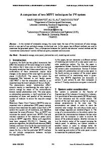
Up - processorutilization Np - number of processors B - systemwith default parametervalues Fall - system with the halved RMMC bus and HIVIMI bus clock cycles, and a faster memory (single memory cycle is 60ns, and the t&t page mode cycle is 2511s). Description: Figure clearly demonstrates improved processox utilization due to lower latency of memory accessesin the f&x variant. It also expressesmuch better scalability of the fate1 variant - a very desirable characteristic that denotesthe ability 01 the systemto deliver the performancedirectly proportional to the system cost (processorutilization is almost constant for different system sizes). Explanation: The above described effect is a result of the much lower waiting of processorto accessthe on-board memory Implication: It can be concluded that the system is expandable to larger node counts without significant processor degradation, and a higher overall system power can be attained even with the sameprocessorcycle time. The s’eumd group of experiments is related to the newly proposedRM/MC++ system (Figures 9 to 13). Again, the figure captions explain all major results and their implications. Figure 9 shows a slight positive impact of the finer sub-block sizes (all later expiments are based on the sub-block size equal to 16 words) on processor utilization. Figures 10 and 11 shed more light on the overall averagepropagation time of short messages and clearly demon&rate the expected effectiveness of the proposed solution. Introduction of separateRM and MC FlFOs evidently ‘decreasesthe turnaround time of short messages comparedto the casewith a single FIFO (which is equivalent to zero data-independence factor), and that was the primary intention of the proposed enhancement The effects are directly proportional for an increaseddata-independencefactor found in an application. The ability to remove the conservative detection of data dependenceduring compile time and to dynamically redirect some quasiRM messagesinto the RM FIFO further cuts the latency of short messagesin quite alike manner. Figure 12 gives the impact of the RM favorization factor (this figure is especially important, becauseit gives the information about the optimal systemdesign for a given application characterizedwith an apriori known value of th RM favotition factor). Finally, Figure 13 gives a quantitative indication of the impact of the chosenarbitration schemefor the accessto on-boardmemory.
0.8 0.6 0.4 0.2 0 8
16
Figure 8: Combined influence of a faster RM/MC! bus, the HPIlIuI bus, and the memory, on the overall system
Figure 6: CPU utilization for various levels of sharing Up - processorutilization Np - number of processors Prx - probability that a write from the RM/MC bus will hit intc an open receive window of the particular processor. Desctiptioa: General conclusion is that processor utilization decreaseswith the increase of the receive probability. Thir decline is more evident as the number of processors grows. Explanation: One of the vital elementsin the RIWhK! system iI the efficient access to the on-board reflective memory. Being three-ported, the RM memory is a potential source of serious contention. The degree of contention is highly dependenton the traffic from the receive buffer port, i.e. from the RMlMC bus. The amount of data being written to memory from this side is directly proportional to the level of sharing in the system.Loom sharing assumes a lower number of open windows - shared reflective memory regions, and tighter coupling of individual nodes results in a larger shared address space mapped into the open windows. Implication: Level of sharing in the system is one of the main characteristicsof the atxGcation be& executedin the svstem.
4
12 NP
NP
up
8
12
16
NP
Figure 7: The influence of a faster RMiMC bus on system pIfOllYUUl~.
Np - number of processors Up - processorutilization B - the RM/MC bus cycles has the default value equal to 75ns RC - RMIMC bus cycles is halved Description: The processorutilization is not affected for a 1owe1 number of processors when the bus bandwidth is not full) utilized. Explanation: Even in the system with 16 processors, the processorutilization is not significantly improved, which means that other system elements are also responsible for system saturation. Implication: This leads to the conclusion that the improving the bus bandwidth itself is not enough for a significantly bettel pI-fOllIl&Ul~.
147
Proceedings of the 28th Hawaii International Conference on System Sciences (HICSS'95) 1060-3425/95 $10.00 © 1995 IEEE
Proceedings of the 28th Annual Hawaii International Conference on System Sciences 0.8 :6’ 0.S
up 0.4
stub-0
0.3
0.1
0.1 0
4
s
12
l5sso mooo 16000 lWO0 5ooo 0
16
4
0
12
0 QO ESO.25 HO.5 n o.7s Ml
NP
NP
Figure 9: Intluence of various sub-block transfer sires on the processorutilization Up - processorutilization Np - number of processors B - there is no sub-blocks s64 - size of each sub-block transfer is 64 words + address S32 - size of each sub-block transfer is 32 words + address S16 - size of each sub-block transfer is 16 words + address Description: The processorutilization increases insigniticantly (only about 1%) with the decreasing of the sub-block transfer size. Exception to this rule is the system with 16 processors,in which the non-increasingtrend can not be noticed. Explanation: The local bus has a lower priority only when the sharedwrite block transfer goes on the host bus, and processoris in the wait state. At the end of the sub-block transfer, the processoris allowed to preempt memory. If the sub-blocks are shorter, the processor will preempt the memory earlier. The performance improvements are not great, because the shared write block transfer on the host bus is sparse. However, the trend is regular, except for the system with 16 processors, becauseof the RM/hK bus saturation effects. Implication: Only the systems with the sub-block transfer size of 16 words will be considered in the rest of this analysis, and will be presented in the subsequent simulation experiments (unless specified differently).
Figure 11: Intluence of the recovery factor (R) - probability thal a qua&M messagecan be moved back into the RM transmit FIFO - on the overall averagepropagation of short messages Sturu - overall averagepropagation time of short messages Np - number of processors Description: The graph is presented for the system with the data-independencefactor of short messagesequal to 0.25. The overall average propagation time of short messages decreases with the increaseof the probability that a quasiRM messagecan be moved back into the RM transmit FIFO. The intluence is higher with increasing number of processorsin the system. Explanation: When increasing the probability that a quasiRlvl messagecan be moved back into the RM trausmit FIFO due to nm time detection of data independence, the number of short independent messages(which run through system with higher priority) increases,so the averageturnaround time is decreased. Because of the saturation effects, the graph does not follow the pattern of Np = 4 all the way to Np=16. Still, the advances of our approach are clearly visible, but not presented because the effects show up for a longer execution time. Implication: The possibility of run-time detection of dataindependent quasiRM messagesenables their return back into the RM transmit FIFO buffer, which moans that the average messagepropagation time is (considerably) decreased. The above results demonstratethe superior performance of the proposed solution, in the applications characterized with a high value of the recovery factor (typical transactions processing applications). Fortunately, preliminary implementation analysis has pointed out that the complexity increaseis minimal. In short, the complexity increase of the RM/MC+I- over the RM/MC* is negligible.
0 00 90.25 n 0.5
80.75
ml
NP
1995
Figure 10: Influence of the data-independencefactor of shoti messages on the overall average propagation time of shoti messages Sturn - overall averagepropagationtime of short messages Np - number of processors Description: The overall averagepropagation of short messages decreaseswith increase of data-independencefactor of shoti messages.The intluence is higher with increasing the number 01 processorin the system. Explanation: With increasing of data-independencefactor of short messages,there is more short messageswhich run through systemwith higher priority, bypassingthe longer block transfers, and the probability is minimized that a short message follows with a delay at& a long one. Because of saturation effect, the graph does not follow the pattern of Np = 4 to 16. Still the advancesof our approach are clearly visible, but not presented becausethe effects ,areevident for a longer execution time. Implication: If there are more data-independentshort messages the overall averagepropagationof short messageswill decrease.
8. Conclusion This paper presents the extensive analysis of the RM/MC concept - a reflective memory approachwhich combines the nondemandedwrite-broadcast coherencemechanism for distributed shared memory on a snoopy bus with the ability to provide the efficient block transfer between different nodes. The work has two major purposes: a) to analyze the behavior of the existing RM/MC in respect to the conditions of typical end-user applications and to various design issues, and b) to introduce and elaborate an improvement which is intended to reduce the turnaround time of short, time-critical messages.The first set of simulation experiments was used to derive the optimal set of system parameters of the interest for the application and to propose the specific design decisions, having in mind cost/performancepoint of view. The second set of experiments starts from this set of optimal parameters and examines the performance of proposed enhancement,proving its effectiveness in specified conditions. Therefore, the results of this analysis are found to be relevant
148
Proceedings of the 28th Hawaii International Conference on System Sciences (HICSS'95) 1060-3425/95 $10.00 © 1995 IEEE
Proceedings of the 28th Annual Hawaii International Conference on System Sciences -
“(Z
36006 26ooo 2wcm 1-
1995
1101 El3
loooo !klwl 0
n 4
0
12
87 mm 16
NP
Figure 12: Influence of the RM favor&ion factor (F) - the maximal number of RM messages followed by one MC or quasiRM message (in each particular node) - on the overall averagepropagationtime of short messages Sturn - overall averagepropagationof ‘short messages Np - number of processors m - the case when a MC messageis sent fi-om the node which wasgrantedtousethebusonlyiftheRMtransmitFIFOonthe TMI hard of that node is empty (logically F tends to infinity) Description: The graph is presented for the system with the data-independencefactor of short messagesequal to 0.5. The fimctions fhm the bar-chart have a minimum (no matter what is the value of Np). This minimum is more obvious as the number of processorsin system increases. Explanation: It is important to give a higher priority to as many short messages as possible, because that makes the system faster. However, it is not recommendedto choose the maximal number of RM message followed by one MC or qua&M messageto be too high, becausethe saturation of the qua&M short messages(from the lower-priority FIFO buffer) makes the overall system slower. Becauseof the saturation effect, the graph does not follow the pattern of Np = 4 all the way to Np = 16. StiIl, the advantagesof our approach are clearly visible in the simulator, but not presentedin the bar-chart, becausethe effects can distort the picture. Implication: For the given value of Np, the best engineering solution is to choose the value for the F factor correspondingto the minimum of the Sturn function. For the case of this tiaure. ” ’ the optimal value of the F factor is equal to three.
NP
Figure 13: Impact of the arbitration scheme for memory access onto the overall averagepropagation time of short messages Stum - overall averagepropagationtime of short messages Np - number of processors X-thecasewhentheRMreceiveFIFObufferhasahigher priority comparedwith the host bus Y-thecarewhentheRMreceiveFIFOb~~hasa~~~ priority compared with the host bus, only when the RM receive FIFO buffer is over half full. Description: The overall average propagation time of short messagesdepends a lot on the utilized arbitration scheme for memory access. The used four-port memory enables a large variety of arbitration schemes to be used. This figure is essentially a comparisonof two d&rent arbitration schemes(X and Y). Explanation: Since the priority of the RM receive FIFO buffer is increased (containing the short data-independentmessages), the long messagesfrom the host bus wiIl not slow down the short messages from the RM receive FIFO but&r. The arbitration schemewhich provides a shorter overall propagation time does include some drawbacks, too. Its averagewaning time for the host bus is (somewhat) increased. tmplication: One has to be careful with the choice of the vbitration scheme, since this choice has an evident impact on lhe performanceof the system.
II
[Jov93]
Jovanovic, M., Tomakvic, M., Mihninovic, V., “A Simulation Study of the RMh4C Proposals,”Final ;F~I for the phase #3, IFACT, Budapest, Hungary,
[Map901 Maples, C., Wittie, L., “Merlin: A Superglue for Multicomputer Systems,” COMPCON ‘90, March 1990, pp. 73-81. [pro951 F’rotic, J., Tomakvit, M., Milutinovic, V., “Tutorial on Distributed Shared Memory: Concepts and ElpklllS,” IEEE Computer Society Press, Los Alamitos, California U.S.A., 1995. VT921 “N.2 Users Manual”, TD Technologies, Cleveland Heights, Ohio, U.S.A., 1992. [Tom931 Tomakvic, M., Milutinovit, V., “Tutorial on Cache Coherence Problem Shared-Memory Multiprocessors: Hard-em solutions ’ IEEE Computer Society Press, Los Alamitos, ‘California U.S.A., 1993. [Tom94a] Tomakvic, M., MiIutinoviC, V., “A Survey of Hardware Solutions for Maintenance of Cache Coherencein Shared Memory Multiprocessors: Part 1,” IEEE Micro, October 1994. [Tom94b] Tomakvic, M., Milutinovic, V., “A Survey of Hardware Solutions for Maintenance of Cache Coherencein Shared Memory Multiprocessors: Part 2,” IEEE Micro, December 1994.
both for application writers and system designersin their strive to obtain the better performanceof the RM/MC system
10. References [Arc861 Archibald J., Baer J.-L., “Cache Coherence Protocols: Evaluation Using a Multiprocessor Simulation Model,” ACM Transactionson Computer Systems, Vo1.4,No.4, November 1986, pp. 273-298. [Get931 Gertner, I., “The Reflective Memory / Memory Channel System Overview,” Encore Computer Systems,Fort Lauderdale,Florida, U.S.A., 1993. [Gru94] Grujic, A., TomaSeviC, M., Milutinovic, V., “A Simulation Analysis of Hardware-Oriented DSM Approaches,” Proceedings of the TENCON-94, Singapore,August, 1994.
149
Proceedings of the 28th Hawaii International Conference on System Sciences (HICSS'95) 1060-3425/95 $10.00 © 1995 IEEE