A Programming Example: Large FFT on the Cell Broadband Engine Alex Chunghen Chow IBM Corporation 11501 Burnet Road Austin, TX 78758
[email protected]
Gordon C. Fossum IBM Corporation 11501 Burnet Road Austin, TX 78758
[email protected]
Daniel A. Brokenshire IBM Corporation 11501 Burnet Road Austin, TX 78758
[email protected]
Abstract The Cell Broadband Engine (CBE, shortname “Cell”) is a nine-core implementation of the Cell Broadband Engine Architecture (CBEA), including a 64-bit Power Processor Element (PPE) and eight Synergistic Processor Elements (SPEs). We apply this processor’s computational power to the calculation of a large FFT, comprising 16 million (224) single-precision complex samples. We present an overview of the CBE, discuss Cell code development methodology, explore the challenges and the tradeoffs of this particular task, describe some implementation details, and present results.
through the execution of the algorithm. A doublebuffering scheme is used to hide DMA latencies. A proper number of Radix-2 FFT stages (butterfly stages) are performed on each batch of elements read in to the SPE to ensure that the computation time is not overwhelmed by the memory access time. Finally, the tasks are uniformly distributed across the SPEs in a way that minimizes the need for synchronization. Our performance numbers demonstrates that the GFLOPS achieved by this FFT implementation are more than an order of magnitude better than the current generation of desktop computers at the same clock rate.
Keywords Cell Broadband Engine (CBE), “Cell”, Synergistic Processor Element (SPE), Fast Fourier Transform (FFT), Single Instruction Multiple Data (SIMD), Direct Memory Access (DMA), FFTW.
Overview of Cell Broadband Engine Many on-chip computational resources are available to Cell programmers. [CBEA05]
Introduction The key to effective utilization of the CBE is to distribute any computational task efficiently and effectively over the eight SPEs. We describe our successful effort to do this on the chosen FFT problem. Our approach considers many factors in order to maximize FFT computation speed. A modified stride-by-1 algorithm proposed by David H. Bailey in 1986 based on Stockham self-sorting FFT is chosen. The stride-by-1 characteristic allows the FFT array to be partitioned naturally, without data rearrangement, into vectors that can be executed in parallel by SIMD instructions. To minimize consumption of memory bandwidth, the number of contiguous sample points is set at 32, which matches the granularity of system storage DMA access. (We’ll call these minimumsize parcels of memory access “memory lines”). Since we can further unroll the 4-way SIMD instructions by a factor of 8, and thereby schedule all instructions into pipelines without incurring any data dependency stalls, the choice of 32 words as a memory granularity is especially serendipitous. A matrix transpose is needed at some point to preserve the availability of these 32-word memory lines as contiguous samples. This approach performs the transposition efficiently by using SPE shuffle-byte instruction and carefully chosen DMA destination addresses part-way
Synergistic Processor Elements for High (Fl)ops / Watt SPE
SPE
SPE
SPE
SPE
SPE
SPE
SPE
LS
LS
LS
LS
LS
LS
LS
LS
16B/cycle EIB (up to 96B/cycle) 16B/cycle
16B/cycle
16B/cycle (2x) MIC
BIC
L2
32B/cycle
PPU L1 16B/cycle
Dual XDRTM
RRAC I/O
64-bit Power Architecture w/VMX for Traditional Computation
The CBE provides more than eight times the compute power of traditional single-core processors. Its SIMD engines are de-coupled from the traditional processor core for growth and scalability. The computational cores
include a PPE and eight SPEs. A data ring with a huge communication bandwidth connects the cores, system memory, and external I/O components together. The PPE provides the capability for traditional computation. It has an in-order instruction execution design to reduce the circuit complexity for smaller chip area and less power consumption. The instructions are dual-issued. The core also supports dual thread SMT to improve performance. In addition, the core is equipped with a VMX engine. The eight SPEs provide the scalable computational capacity. The SPE architecture and instruction set support up to 16-way SIMD to exploit data parallelism. Each SPE has its dedicated set of resources. Its 128 128-bit vector registers provide compilers or low-level programmers with a generous register set for frequently used variables. The address architecture of each SPE contains a 256kilobyte memory space called local store. This local store is placed physically next to the SPE core. Such closeness gives the SPE core a 51.2 GBs per second bandwidth for both instruction fetching and data load/store. Each SPE core is equipped with a DMA controller. This controller allows an SPE to exchange data between its local store and any resources connected to the data ring – e.g. system memory, local stores of other SPEs, and I/O components. In addition, the DMA controller also has a collective 51.2 GBs per second bandwidth into the Element Interconnect Bus (EIB). Common Cell Software Design Considerations A Cell programmer must consider the following factors when developing a CBE program in order to exploit the many computational resources. A CBE by its nature is a multi-core parallel processing system. The existing practice of parallel programming is readily applicable. A Cell programmer should consider two levels of parallelism granularity. One is the data level parallelism supported by the SIMD and VMX instructions. Each SIMD instruction operates on a full 128-bit register, so depending on the size of the data, a single SIMD instruction may be able to process 16 elements at the same time. The other level of granularity is the task level parallelism supported by the nine heterogeneous cores. The SPE DMA data transfer overhead among the resources is a critical design consideration for performance. Transferring large amount of data with a DMA controller takes up time. In some cases, the latency is larger than the time required for an SPE to process the data itself. By overlapping the DMA transaction and the SPE’s instruction execution, a Cell programmer can effectively hide the DMA latency and improve the performance of a program.
The SPE DMA transfer has a granularity and alignment of 128 bytes. To utilize bandwidth effectively, the programmer is encouraged to align the data to 128-byte boundaries and transfer data in multiples of 128 bytes. The size of the local store is also a factor to consider. Considering the program performance and development cost, it is desirable to have the working set of an SPE program resides completely in the 256 KB local store. In the STI Design Center, we have developed samples and workloads in many application domains that fit in the local store. However, if needed, programming techniques such as code/data overlay or software data cache can still be applied. Some advanced compilers, e.g. a CBEAenabled prototype xlc compiler for SPE, can generate software cache code automatically. Typical Cell Programming Models The CBEA is capable of supporting many programming models effectively. Depending on the characteristics of an application, one programming model may be more costeffective than others. The heterogeneous nature of the PPE and SPE cores mandates that the SPE executable and call stack be different from the PPE ones. A compiler and operating system runtime may further build a shared-memory abstraction on top of this SPE thread model. However, early Cell programmers have found this model to be very intuitive and effective especially when developing new parallel programs. A given operating system may alternatively expose an SPE core as a device. This model is simpler when porting an existing application where the main structure of the program will not alter much and the interaction between the device and the rest of the program can be effectively modeled as device I/O. A programmer can then off-load a function directly to the SPE device. With limited sharing between the main program and the device, the message passing or streaming programming model may arguably be a natural abstraction on top of this low level model. Regardless of which low-level model the kernel exposes, an SPE runtime management library usually provides a Cell programmer enough facility, among the other necessities, to load, start, communicate with, and stop a SPE program. An Effective Cell Software Development Flow Early Cell programmers adopted a series of development stages that are very effective. Certain stages may be optional depending on the need of a particular application.
• Algorithm complexity study – The algorithms of a program must be studied in detail to understand the characteristics of its parallelism. In particular, the programmer needs to understand the computational overhead of executing on an SPE or
•
•
•
•
•
•
•
PPE either in SIMD or scalar code. This stage provides a set of possible parallelizable partitions and mappings from computation to the available resources. Communication analysis – For a possible mapping or partition of the computation task, a programmer can analyze the required communication. This provides additional information for a proper partitioning and mapping. Experimental partitioning and mapping – Possible programming models, load balancing, computational overhead, and DMA latencies are common factors used to determine an initial partition and mapping. An on-paper experiment against the available resource is usually sufficient as a base for subsequent stages. PPE control program / PPE scalar code – Developing the algorithm in scalar code provides the programmer not only a base program structure but also a deeper understanding of the algorithm. The scalar code can be further used as a verification tool for subsequent parallelization. SPE scalar code replacement – Partition-able PPE code segments can be replaced by SPE scalar code. This stage allows the programmer to develop the communication, synchronization, and latency hiding functions. This stage can display the performance improvement from the task level parallelism. SPE SIMD code development – The programmer re-implements the SPE scalar code in SIMD to exploit the data parallelism. This can give another boost of performance. Partitioning / Mapping re-balance – In some cases, the partitioning and mapping needs to be re-adjusted to balance the computational and memory bandwidth requirements. Other optimization considerations – Many times a particular algorithm may not use all SPEs equivalently. Load balancing and bottleneck removal are common Cell programming practice. In addition, the VMX engine in the PPE core can give another opportunity for performance improvement.
The FFT Example: Challenges The Fast Fourier Transform (FFT) is one of the most important algorithms in the last several decades. Its applications range from image and signal processing to partial differential equations (PDEs). With a multi-core SIMD implementation of the CBEA, the CBE has the capacity to perform huge computational tasks on a single chip. We use an example of a large FFT implementation of 16,777,216 (224) single-precision complex numbers to
demonstrate this capacity. The real and imaginary parts of the input data are stored as two separate arrays - a total of 128 MB of memory requirement just for input data. Furthermore, we maintain a working array of the same size in main memory, as we chose to not implement an inplace solution. Such a large FFT implementation offers several performance challenges both to traditional processors and to the CBE. • The large data array cannot fit into the on-chip cache or on-chip memory. For a CBE, we have eight 256 KB “local stores”, one for each SPE (total: 2 MB). It is inevitable that we have to stream the data between the system memory and local stores multiple times during the algorithm execution. • The I/O bandwidth required to reading and writing to/from main memory after each butterfly cycle, running simultaneously on all eight SPEs will far exceed the 25.6 GB/s bandwidth of the CBE. Performance is capped by the memory bandwidth if we do not increase the amount of work done on each batch of data collected from main memory. We conclude that multiple butterfly stages should be performed in each SPE, to avoid being memorybound. • The data decimation (either decimation-in-time or decimation-in-frequency) of an FFT implementation introduces data access inefficiency if we wish to read and write our data in 128-byte parcels. When the granularity of the access irregularity falls below this DMA transfer granularity, large memory-access inefficiencies result. Addressing the Challenges We developed a variation on the stride-by-1 algorithm proposed by David H. Bailey [Bailey88] based on the Stockham self-sorting FFT. Hegland also described the same index bit manipulation basis for this class of techniques [Hegland94]. It specifically solves the datagranularity difficulty by performing index-bit permutation at the end of each radix-2 butterfly stage. In order to reduce the memory bandwidth requirement, we bundle the butterfly stages into groups of eight, so that each SPE can read in a batch of data, perform eight full stages of butterfly operations on it before writing out a batch of result data. We solve the data decimation problem by performing a series of 4x4 matrix transpositions in local store before writing out the results at the end of the first bundle of eight butterfly cycles (effectively implementing a 2-D matrix transposition on a 256x65536 matrix representation of the 224 array). The manipulation on the 24-bit array indices is summarized in the following table.
Basic Algorithm illustration – 24-bit index bit manipulation 00 01 02 03 04 05 06 07 08 09 10 11 12 13 14 15 16 17 18 19 20 21 22 23 Stage 1 00 01 02 03 04 05 06 07 08 09 10 11 12 13 14 15 16 17 18 19 20 21 22 23 Stage 2 01 00 02 03 04 05 06 07 08 09 10 11 12 13 14 15 16 17 18 19 20 21 22 23 Stage 3 02 01 00 03 04 05 06 07 08 09 10 11 12 13 14 15 16 17 18 19 20 21 22 23 Stage 4 03 02 01 00 04 05 06 07 08 09 10 11 12 13 14 15 16 17 18 19 20 21 22 23 Stage 8 07 06 05 04 03 02 01 00 08 09 10 11 12 13 14 15 16 17 18 19 20 21 22 23 2D Matrix Trans.
a0a1a2a3a4a5a6a7b0b1b2b3b4b5b6b7c0c1c2c3c4c5c6c7
Stage 9
After the “internal part” of Megastage A, the addresses would be reversed in the first 8 bits:
Stage 10
a7a6a5…a0b0b1b2…b7c0c1c2…c7
Stage 23
but with judicious use of 4x4 transposes, we are able to write the data out to memory at the address of index
08 09 10 11 12 13 14 15 16 17 18 19 20 21 22 23 07 06 05 04 03 02 01 00 09 08 10 11 12 13 14 15 16 17 18 19 20 21 22 23 07 06 05 04 03 02 01 00 10 09 08 11 12 13 14 15 16 17 18 19 20 21 22 23 07 06 05 04 03 02 01 00
23 22 21 20 19 18 17 16 15 14 13 12 11 10 09 08 07 06 05 04 03 02 01 00 23 22 21 20 19 18 17 16 15 14 13 12 11 10 09 08 07 06 05 04 03 02 01 00
and can process its portion by looping 256 times, processing 8192 elements in each loop iteration. One complication of this is that it is necessary to permute the bottom five bits at some point, and we choose to do that within the SPE before we write out the results of processing each batch of 8192 elements in Megastage A. To see the effect of each megastage on the locations of the data in the large array, let’s re-name the 24 bits in the address space as
Stage 24
Each stage represents a Radix-2 butterfly stage. The 2-D matrix transposition may be placed between any two stages where the data decimation is above the required data granularity. Array Index Permutation Implementation Details To recapitulate, the basic solution is to perform a series of 24 butterfly stages (indexed 0 through 23) on a large array (each cycle consisting of 223 traditional radix-2 butterflies), and write the data back out to memory in a permuted fashion such that if a word is read in from array index
b0b1be…bi…b22b23 at the beginning of butterfly cycle i, then we compute the output array index to be
bib0b1b2…bi-1bi+1…b22 b23 and we store the data to that location at the end of the butterfly cycle. The first improvement derives from the fact that if we read 512 well-chosen memory lines into local store (256 real, 256 imaginary), we can perform eight full butterfly stages on the resulting 8192 complex samples, and write out the memory lines in permuted fashion, as long as we don’t permute the bottom five bits. This function (taking 8192 samples and performing an octet of butterfly stages on them) forms the core of our SPE processing. Note that by organizing the algorithm in this fashion, we can do the entire FFT by touching each memory location exactly six times (three reads and three writes). We call these large operations (the first, second and third octets of butterfly stages) “megastages,” labeling them Megastage A, Megastage B and Megastage C. Within each megastage, each of the eight SPEs will be responsible for one eighth of the elements of the array,
b0b1b2…b7c0c1c2…c7a7a6a5…a0 Megastage B reads this address in, and writes it out to location
c0c1c2…c7b7b6b5…b0a7a6a5…a0 Megastage C reads this address in, and writes it out to location
c7c6c5…c0b7b6b5…b0a7a6a5…a0 and we have succeeded in completely reversing (or bitmirror-imaging) the address. Let us summarize the algorithm: Eight SPEs operating in parallel, executing Megastage A, Megastage B and Megastage C, synchronizing at the end of each Megastage. Each megastage comprises, for each SPE, a loop of 256 code blocks consisting of the following three operations: • read in 8192 array elements • perform eight sets of butterfly stages on these elements • write out the resulting elements to a permuted address (Megastage A includes the matrix transforms referred to in the preceding figure.) Other Implementation Details There are six components to this implementation which we shall explore further: synchronization, DMA, MultiBuffering, Loop Unrolling and 4-way SIMD, Twiddle Factors, and data interleaving/offsets. Synchronization The three megastages (Megastage A, Megastage B, and Megastage C) need to be kept separate. For example, we can’t have any SPEs start processing their Megastage B function until all SPEs have successfully written out their Megastage A results.
Several features exist in the CBEA to implement this. We chose to use simple message passing between the SPEs and the PPE, since the PPE is not otherwise occupied. So, the PPE waits to hear from all eight SPEs that they have finished Megastage A, and then the PPE sends messages to all eight SPEs indicating that they can now begin processing Megastage B.
Note that the 8-way loop unrolling and the 4-way SIMD lead us to process 32 butterflies in one iteration of the inner loop. Recall that each butterfly operation takes two complex numbers as input, and outputs two updated complex numbers. So, that’s 16 bytes input and 16 bytes output per butterfly, or 1 kbyte of memory bandwidth per inner loop.
DMA The operations of reading in and writing out the 8192 array elements are implemented by reading and writing 512 128-byte memory lines (256 real, 256 imaginary). This happens to be the native size of read and write blocks on the CBEA, so we achieve optimal DMA bandwidth usage. The first task in this process computes a list of addresses and lengths, and submits that list to the DMA engine. (The DMA engine can accept a wide variety of lengths, but for this algorithm, the lengths will always be specified as 128 bytes.) The resulting two blocks of data (32KB real and 32KB imaginary) which are delivered by the DMA engine reside in the local store of the SPE, and can then be accessed in fully pipelined fashion by the butterfly code. After the octet of butterfly cycles is complete, the resulting data is written back out to main memory, using a second DMA list (addresses and lengths), which is also generated during this process.
Twiddle Factors We had several choices, regarding the “twiddle factors.” We could pre-compute them all, and read them in as needed, we could compute them all on the fly, as part of the SPE code, or we could do some combination of the two, reducing the number of table lookups to the point that they will fit in the SPE, and not require bandwidth to/from main memory, and taking advantage of trigonometric identities, to simplify the task. We chose this third option, as it represented both a minimal increase in memory bandwidth and computation cycles. The data size for the pre-computed sin and cos arrays added up to 6k on each SPE (out of 256k total). In Megastage A, the twiddle factor granularity was coarse enough that we could use these pre-computed numbers directly, with no additional computations. In Megastages B and C, we needed to compute eight sin and eight cos values for every 8192 elements processed. The required work to compute the trigonometric identities which fine tune these results add up to 48 extra floating point operations (at a cost of 32 extra cycles) per iteration of the inner loop. To recap, this inner loop is hand-unrolled code which computes 64 updated complex numbers, as the result of 32 individual butterfly operations. Thus, the amortized cost of these trig identities was half a cycle per updated complex number, in each of the eight SPEs.
Multi-Buffering The latency for loading and storing these 32KB blocks of data into the local store is large (several thousands of SPE cycles) so we implement a multi-buffering scheme which allows us to fully hide these DMA cycles behind the butterfly processing. While the butterfly code is processing block n, the DMA engine is loading the data for butterfly block n+1, and writing out the data for block n-1. Loop Unrolling and 4-Way SIMD The latency for most SPE instructions is four or six SPE cycles. However, single-precision operations are fully pipelined, so we manually unroll our butterfly processing loops by a factor of eight, to ensure that the compiler can achieve this full pipelining without incurring any stalls from data dependencies. Everything in the SPEs is done in quadword (16 byte) granularity. For single-precision floats, that corresponds to 4-way SIMD operation. Since the butterfly operations are always accessing pairs of elements in the data arrays which are separated by a multiple of four elements (that is, the bottom two bits of their indices match), we can code the entire octet of butterfly stages in full 4-way SIMD.
Data Interleaving/Offsets The off-chip memory accessed by the CBE is organized into 16 “memory banks,” such that the first 128 bytes of memory are in bank 0, the next 128 bytes are in bank 1, etc., cycling back to bank 0 every 2048 bytes. Since our large arrays of data are all naturally aligned on boundaries in bank 0, and since we have eight SPEs, we found that we were frequently accessing eight of the sixteen memory banks very heavily, and essentially ignoring the other eight, for long periods of time. We discovered that if we aligned the beginning of the arrays so that the arrays of real data started with bank 0, and the arrays of imaginary data started with bank 8, we achieved a more balanced utilization of memory bandwidth, and a significant improvement in performance.
Results Source Code Size The C code (including unrolled SPE intrinsics) which implements all of the processing of 8192-element subsets of the array adds up to around 460 lines of code (not including the declarations of the sin and cos lookup tables). The C code which implements all of the DMA activity, including double-buffering, adds up to around 130 lines of code. Object Code Size The resulting executable code on each SPE fits within 39 kbytes, and the arrays occupy 198 kbytes, for a total size of 237 kbytes (out of a maximum available space of 256 kbytes). Accuracy The input array is filled with a simple real-only function: f(x) = 7.0 + sin(x) + cos(2x) (Of course, any function would suffice, as the amount of computation does not depend on the values being processed) After processing through a full cycle (time domain to frequency domain, and back again) the results are compared with the original function. The error envelope is as follows: real: (-0.000008, 0.000006) imaginary: (-0.000004, 0.000004) Performance The code was executed on a 3.2 GHz Cell BE in our lab in Austin. We determined that one execution of this FFT required 0.043 seconds of clock time.
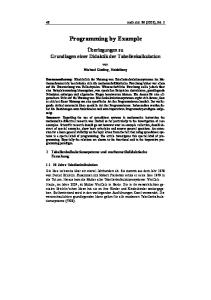
Performance Comparison 50 40 30 20 10 0 GFLOPS
Leading Brand @2GHz
Pow er 5 @1.65GHz
CBE @3.2GHz
1.20
1.55
46.80
Using the standard “5 N log N” metric for FFT floatingpoint operations, we computed that this corresponds to 46.8 GFlops/second. Matteo Frigo of IBM Research, co-creator of the FFTW subroutine library, reports that a 1.65 GHz Power5 can compute this FFT in 1.3 seconds using the FFTW library, which corresponds to 1.55 GFlops. He also provided a performance result on a leading brand workstation, running at 2.0 GHz. That machine computed this FFT (using the FFTW library) in 1.7 seconds, or 1.2 GFlops (see chart). References [Bailey88] David H. Bailey, “A High-Performance FFT Algorithm for Vector Supercomputers”, Intl. Journal of Supercomputer Applications, vol.2, no. 1, 1988 [CBEA05] Cell Broadband Engine Architecture Document, 2005 [Hegland94] Markus Hegland, “A self-sorting in-place fast Fourier transform algorithm suitable for vector and parallel processing”, Numerische Mathematik, 68, 1994 Authors Alex Chunghen Chow is a senior programmer and a software development manager in the STI Design Center (Austin, Texas). He leads a team developing workloads, libraries, demo, and samples for the CBE chip bring-up. He received a BS and MS degrees in electronic engineering from National Chiao-Tung University, Taiwan. He also received a Ph.D. degree from the University of Arizona in electrical and computer engineering. His fields of work include discrete event simulation, distributed and parallel simulation/programming, and object-oriented programming and framework. Gordon C. Fossum graduated from the University of Illinois at Urbana-Champaign with a BS in Math and Computer Science. He received a Master's degree from the University of California, Berkeley. He has been employed by IBM in Austin, Texas, for the past 17 years, the majority of which was spent working in workstation graphics software. He enjoys any opportunity to force the bits and bytes to submit to his authority, and is a big fan of the Cell Broadband Engine. Daniel A. Brokenshire is a senior technical staff member in the STI Design Center (Austin, Texas). His responsibilities include the development of programming standards, language extensions, and reusable software libraries for the CBE. He received a BS in computer science and BS and MS degrees in electrical engineering, all from Oregon State University.
© IBM Corporation 2005 IBM Corporation Systems and Technology Group Route 100 Somers, New York 10589 Produced in the United States of America May 2005 All Rights Reserved This document was developed for products and/or services offered in the United States. IBM may not offer the products, features, or services discussed in this document in other countries. The information may be subject to change without notice. Consult your local IBM business contact for information on the products, features and services available in your area. All statements regarding IBM future directions and intent are subject to change or withdrawal without notice and represent goals and objectives only. IBM, the IBM logo, Power Architecture, are trademarks or registered trademarks of International Business Machines Corporation in the United States or other countries or both. A full list of U.S. trademarks owned by IBM may be found at: http://www.ibm.com/legal/copytrade.shtml. IEEE and IEEE 802 are registered trademarks in the United States, owned by the Institute of Electrical and Electronics Engineers. Other company, product, and service names may be trademarks or service marks of others. Photographs show engineering and design models. Changes may be incorporated in production models. Copying or downloading the images contained in this document is expressly prohibited without the written consent of IBM All performance information was determined in a controlled environment. Actual results may vary. Performance information is provided “AS IS” and no warranties or guarantees are expressed or implied by IBM THE INFORMATION CONTAINED IN THIS DOCUMENT IS PROVIDED ON AN "AS IS" BASIS. In no event will IBM be liable for damages arising directly or indirectly from any use of the information contained in this document.