INTERNATIONAL JOURNAL FOR NUMERICAL METHODS IN ENGINEERING Int. J. Numer. Meth. Engng 2000; 00:1–6 Prepared using nmeauth.cls [Version: 2002/09/18 v2.02]
A meshfree thin shell method for nonlinear dynamic fracture T.Rabczuk † , P.M.A.Areias+ , T.Belytschko∗,k Department of Mechanical Engineering, Northwestern University, Evanston, IL 60208-311, U.S.A
SUMMARY A meshfree method for thin shells with finite strains and arbitrary evolving cracks is described. The C 1 displacement continuity requirement is met by the approximation, so no special treatments for fulfilling the Kirchhoff condition are necessary. Membrane locking is eliminated by the use of a cubic or quartic polynomial basis. The shell is tested for several elastic and elasto-plastic examples and shows good results. The shell is subsequently extended to modelling cracks. Since no discretization of the director field is needed, the incorporation of discontinuities is easy to implement and straight c 2000 John Wiley & Sons, Ltd. forward. Copyright ° key words:
meshfree methods, cracks, cohesive models, KL constraint, shell
1. INTRODUCTION This paper describes a meshfree method for treating the dynamic fracture of shells. It includes both geometric and material nonlinearities and also includes a meshfree fluid model, so that complex fluid-structure interaction problems are feasible. Here we illustrate this capability with the fracture of a fluid-filled cylinder that is impacted by a penetrating projectile. The shell formulation is based on the Kirchhoff-Love (KL) theory. A meshfree thin shell based on the imposition of the KL constraints was first proposed by Krysl and Belytschko [1]. However, the shell was developed for small deformations, small strains and elasticity. Three dimensional modelling of shear deformable shells and degenerated shells in a meshfree context was studied by Noguchi et al. [2], Li et al. [3] and Kim et al. [4]. Usually, a low order polynomial basis was used, e.g. in [3], a trilinear polynomial basis was applied and the method was applied to several non-linear problems. However, for thin structures, three dimensional modelling of shell structures is computationally expensive. Garcia et al. [5] developed meshfree methods for plates and beams; the higher continuity of meshfree shape functions was exploited for Mindlin-Reisner plates in combination with a p-enrichment. Wang and Chen [6] proposed a meshfree method for Mindlin-Reisner plates. Locking is treated using
∗ Correspondence to: T. Belytschko, Department of Mechanical Engineering, Northwestern University, 2145 Sheridan Road, Evanston, IL 60208-311, U.S.A. E-mail:
[email protected] k Walter P.Murphy, Professor of Computational Mechanics †, + Post-Doctoral Research Fellow, Department of Mechanical Engineering
c 2000 John Wiley & Sons, Ltd. Copyright °
Received Revised
2
T. RABCZUK, P.M.A. AREIAS, T. BELYTSCHKO
second order polynomials for the approximation of the translational and rotational motion in combination with a curvature smoothing stabilization. Kanok-Nukulchai et al. [7] addressed shear locking for plates and beams in the element-free Galerkin method. We develop a meshfree thin shell that combines classical shell theory with a continuum based shell. The kinematic assumptions of classical KL shell theory is adopted. We make use of the generality provided by the continuum description, so that constitutive models developed for continua are easily applicable to shells. The formulation is valid for finite strains. We include in the shell the capability to model cracks, which are modeled either by cracked particles as in Rabczuk and Belytschko [8] or by a local partition of unity [9, 10, 11]. Due to the higher order continuity of meshfree methods, which enables the use of KirchhoffLove shell theories in pristine form, the incorporation of discontinuities is very simple and straight forward. The director field is not discretized, which simplifies the incorporation of discontinuities. In our meshfree model, the concepts for modelling cracks in continua can be adopted directly to shells. The paper is arranged as follows: First, the kinematics of the shell is described. Then, the meshfree method, the element-free Galerkin (EFG) method, is reviewed and the concept how to incorporate continuum constitutive models is described. The extensions to modelling cracks is described in section 5. Finally, we test the meshfree shell for different elastic linear and nonlinear problems, plastic problems and cracking problems.
2. SHELL MODEL 2.1. Kinematics Consider a body Ω with material points X ∈ Ω0 of the shell in the reference configuration with discontinuities, e.g. cracks, on lines Γc0 . The boundary is denoted by Γ0 , where Γu0 and Γt0 are the complementary boundaries on which, respectively, displacements and tractions are prescribed. We consider a surface parametrized by two independent variables θ α , α = 1 to 2; the surface in the reference (initial) configuration is described by R(θ α ), R ∈ 1 ∀fI (θα ) < 1
(29)
Int. J. Numer. Meth. Engng 2000; 00:1–6
A DEMONSTRATION OF THE INT. J. NUMER. METH. ENGNG CLASS FILE WITH FLUID-STRUCTURE INTERACTION7
Table I. The return mapping in the material setting; encapsulation of the small strain case
Make C p0 = I (and therefore C 0p = I) and ξ 0 = 0 for all quadrature points For each quadrature point at time-step n, perform the following calculations 1) Using the current position field x calculate C n+1 = (x,α · x,β )Gα ⊗ Gβ with Gα = Gαβ X ,β and [Gαβ ] = [X ,α · X ,β ]−1 p−1 2) Calculate the trial of the elastic measure C E n? = C n+1 C n 3) Use a second order Pad´e approximation to calculate εn? = 21 ln C E n? 4) Using a modified (unsymmetric) small strain return-mapping algorithm, update ξ n and calculate εn+1 ∆α, Σ and the small strain consistent modulus C −1 5) Calculate the new plastic metric inverse as C p−1 n+1 = C n+1 exp[2εn+1 ] using a first order Pad´e approximation for the exponential function 6) Calculate the contravariant components of the stress as ³ ´ sαβ = Gα · C −1 ΣGβ −1
and the contravariant components of the tangent modulus as C αβγδ = Gαi Gβj Gγk Gδl Cijkl where Cijkl is the elasticity tensor and Gαi = Gα · ei for any i = 1, 2, 3 and α = 1, 2. ξ 0 are a set of internal variables, α is the plastic parameter of the yield surface and Σ are the elastic stresses.
Note that, in general, different shape functions can be used for the continuous and discontinuous parts. Since at least second order complete basis polynomials have to be used, the domains of influence are large and the cracked particles will influence more particles than in the continuum version of this method [8]. Note also, that in [8, 13], the method was developed for a stress point integration where stresses are evaluated at nodes and stress points. In this approach, the nodal stresses are obtained by MLS fits.
5.2. Method 2: Local Partition of Unity approach In this approach, we enrich the test and trial functions with additional unknowns so that the crack is continuous and includes branch functions at the tip as in Moes et al. [10], Ventura et al. [11]. Therefore, the test and trial functions in terms of a signed distance function f , see figure 2, are c 2000 John Wiley & Sons, Ltd. Copyright ° Prepared using nmeauth.cls
Int. J. Numer. Meth. Engng 2000; 00:1–6
8
T. RABCZUK, P.M.A. AREIAS, T. BELYTSCHKO
Ws (X) φ Xtip
r
XI
f>0 f=0
Wb (X) PSfrag replacements
f 700m/s), the failure pattern of water-filled cylinders differs substantially from c 2000 John Wiley & Sons, Ltd. Copyright ° Prepared using nmeauth.cls
Int. J. Numer. Meth. Engng 2000; 00:1–6
A DEMONSTRATION OF THE INT. J. NUMER. METH. ENGNG CLASS FILE WITH FLUID-STRUCTURE INTERACTION19
Figure 13. Deformed plastic pinched cylinder with end diaphragms
that of the empty cylinders. While a small hole was usually punched into the cylinder for low impact velocities or empty cylinders, for high impact velocities, the water filled containers crack over almost the entire length at the side where the projectile enters; (see figure 22a), for an impact velocity around 730m/s. When the container is completely filled with water, a double triangle shaped crack opening is typical. We consider empty and water filled containers. We used the Johnson-Cook [49] model. The material data is given by Timm [48]: A = 175KN/cm2 , B = 380KN/cm2 , n = 0.32, m = 0.55, Tm = 1538C, Tr = 25C and fracture energy Gf = 22, 000J/m2 . An exponential cohesive law described in section 5.3 is used. We study two different refinements with 29,000 and 114,000 particles for the cylinder. The deformed cylinder including the deformed projectile at 0.6ms is shown in figure 21a. The principal failure mechanism is reproduced well. In figure 21b the deformed water filled cylinder is shown. A severe failure at the entrance side occurs that was also observed in the experiments. In figure 22, the final deformation of the cylinder is compared to the experiments. Figure 22d shows the deformed cylinder if the failure is modelled by softening to zero stress; a length scale parameter was introduced. As can be seen, the double-triangle crack opening typical for Timm’s experiments cannot be reproduced. The deformed cylinder for the cracked particle method is shown in figure 22b) and c). The results for the PU cracking method are similar. c 2000 John Wiley & Sons, Ltd. Copyright ° Prepared using nmeauth.cls
Int. J. Numer. Meth. Engng 2000; 00:1–6
20
T. RABCZUK, P.M.A. AREIAS, T. BELYTSCHKO
6000
key:
5000
Meshfree Areias 2005 Eberlein 1999 Wagner 2002
4000
3000
2000
1000
0
0
50
100
150
200
250
300
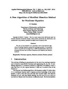
Figure 14. Load deflection curve of the plastic pinched cylinder with end diaphragms compared to the results of Areias et al. [26], Eberlein and Wriggers [43], Wagner et al. [44]
E = 210 GPa ν = 0.3 σy = 574(0.010372 + εp )0.26 MPa σmax = 306 MPa Gc = 255 kJ/m2
Clamped edges
0.8 F
F a0 Initial crack
203
203
All linear dimensions are in mm
Figure 15. Test setup of the out-of plane plate tearing problem, [45]
c 2000 John Wiley & Sons, Ltd. Copyright ° Prepared using nmeauth.cls
Int. J. Numer. Meth. Engng 2000; 00:1–6
A DEMONSTRATION OF THE INT. J. NUMER. METH. ENGNG CLASS FILE WITH FLUID-STRUCTURE INTERACTION21
Figure 16. Deformed torn out-of plane loaded plate for a value of a0 = 40mm
(a)
(b)
Figure 17. a) Load deflection curves for different values of a0 for the torn out-of plane loaded plate compared to experimental data of Muscat-Fenech and Atkins [45] and b) Influence of the refinement
c 2000 John Wiley & Sons, Ltd. Copyright ° Prepared using nmeauth.cls
Int. J. Numer. Meth. Engng 2000; 00:1–6
22
T. RABCZUK, P.M.A. AREIAS, T. BELYTSCHKO
E = 71422 MPa ν = 0.3 σy = 520.51(0.0483 + εp )0.0455825 MPa σmax = 460 MPa Gc = 5 N/mm
991 406.4
R228.6
p
p
Crack
20
2a0 = 101.6 1.02
All dimensions are in mm 50.8
(the cylinder ends are considered to be flexible)
50.8
Tear straps, thickness=3.962
Figure 18. Relevant data for the pressurized shell problem, see also references [46, 47]
Both methods are able to reproduce the shape of the crack. Note that due to fabrication errors, the cylinder shown failed also across a weld at the top. This failure was not observed in several other experiments.
7. CONCLUSIONS We have presented a meshfree thin shell formulation for finite strains and its extension to plasticity and crack modelling. Due to higher order displacement continuity of meshfree methods, when compared with finite elements, the incorporation of strong discontinuities is especially simple. We proposed two methodologies, a cracking particle method [8, 13] where the crack is introduced at the particle position and a local partition of unity PU method as in Ventura et al. [11]. In the latter case, the crack is modelled as a continuous line. A methodology allowing the adoption of continuum constitutive models in the shell framework was presented, see also Areias et al. [19]. Local patches are used for the surface parametrization. The method required a parametric C 1 description of the initial shape. For the problems considered here, namely cylinders and spheres or portions thereof, this is straightforward. For more complex shapes, B-spline representations (or similar CAD techniques) would need to be used. While this was a marked disadvantage several decades ago, it is quite straightforward today, though techniques for identifying neighbors on adjacent patches would need to be developed. We tested the method and the implementation with linear and nonlinear benchmark problems. No membrane locking was observed and the results showed good accuracy in c 2000 John Wiley & Sons, Ltd. Copyright ° Prepared using nmeauth.cls
Int. J. Numer. Meth. Engng 2000; 00:1–6
A DEMONSTRATION OF THE INT. J. NUMER. METH. ENGNG CLASS FILE WITH FLUID-STRUCTURE INTERACTION23
a)
(b)
c)
d)
e)
f)
Figure 19. Deformed Keesecker et al. [46] cylinder for 37,500 particles and the cracking particle method at different times c 2000 John Wiley & Sons, Ltd. Copyright ° Prepared using nmeauth.cls
Int. J. Numer. Meth. Engng 2000; 00:1–6
24
T. RABCZUK, P.M.A. AREIAS, T. BELYTSCHKO
0.35 0.3
Pressure [MPa]
0.25 0.2 0.15 experimental results 9,400 particles 37,500 particles
0.1 0.05 0 40
60
80
100
120
140
160
180
Self similar crack size [mm]
Figure 20. Self similar crack opening versus pressure for the Keesecker et al. [46] problem
a) without water
(b) with water
Figure 21. Deformation of the cylinder c 2000 John Wiley & Sons, Ltd. Copyright ° Prepared using nmeauth.cls
Int. J. Numer. Meth. Engng 2000; 00:1–6
A DEMONSTRATION OF THE INT. J. NUMER. METH. ENGNG CLASS FILE WITH FLUID-STRUCTURE INTERACTION25
a) experiments
(c) 114,000 particles
b) 29,000 particles
(f) 29,000 particles
Figure 22. Deformed impacted full cylinder for different methods compared to a) the experimental result);b) and c) cracking particle method, d) ”smeared” crack method c 2000 John Wiley & Sons, Ltd. Copyright ° Prepared using nmeauth.cls
Int. J. Numer. Meth. Engng 2000; 00:1–6
26
T. RABCZUK, P.M.A. AREIAS, T. BELYTSCHKO
comparison with other results from the literature. The method was also applied to static and dynamic crack propagation. We found that the cracking particle method is well suited for a qualitative prediction though in some cases the quantitative agreement with epxeriments was not as good as for the PU method. This is probably due to the large domain of influence that is necessary for the higher order meshfree shape functions that are needed for the higher order approximations. An alternative would be to use Shepard functions and an extrinsic basis with additional degrees of freedom to meet quadratic or higher order completeness. This is a topic of ongoing investigations. The PU method was able to give good quantitative results as compared to experiments. This is probably due to the fact that linear crack opening can be reproduced more correctly than with the cracking particle method. However, difficulties occur for high velocity dynamic problems with multiple cracking and fragmentation since certain criteria and assumptions have to be made as to how to branch and join the cracks.
8. ACKNOWLEDGEMENT The support of Office of the Naval Research under Grant N00014-03-1-0097 and the Army Research Office under Grant DAAD19-02-01-0339 is gratefully acknowledged.
c 2000 John Wiley & Sons, Ltd. Copyright ° Prepared using nmeauth.cls
Int. J. Numer. Meth. Engng 2000; 00:1–6
A DEMONSTRATION OF THE INT. J. NUMER. METH. ENGNG CLASS FILE WITH FLUID-STRUCTURE INTERACTION27
references [1] P. Krysl and T. Belytschko. Analysis of thin shells by the element-free galerkin method. International Journal of Solids and Structures, 33(20-22):3057–3078, 1996. [2] H. Noguchi, T. Kawashima, and T. Miyamura. Element free analysis of shell and spatial structures. International Journal for Numerical Methods in Engineering, 47(6):1215–1240, 2000. [3] S. Li, W. Hao, and W.K. Liu. Numerical simulations of large deformation of thin shell structures using meshfree methods. Computational Mechanics, 25(2-3):102–116, 2000. [4] N.H. Kim, K.K. Choi, J.S. Chen, and M.E. Botkin. Meshfree analysis and design sensitivity analysis for shell structures. International Journal for Numerical Methods in Engineering, 53(9):2087–2116, 2002. [5] O. Garcia, E.A. Fancello, C.S. de Barcellos, and C.A. Duarte. hp-clouds in Mindlin’s thick plate model. International Journal for Numerical Methods in Engineering, 47(8): 1381–1400, 2000. [6] D.D. Wang and J.S. Chen. Locking-free stabilized conforming nodal integration for meshfree Mindlin-Reissner plate formulation. Computer Methods in Applied Mechanics and Engineering, 193(12-14):1065–1083, 2004. [7] W. Kanok-Nukulchai, W. Barry, and K. Saran-Yasoontorn. On elimination of shear locking in the element-free galkerin method. International Journal for Numerical Methods in Engineering, 52(7):705–725, 2001. [8] T. Rabczuk and T. Belytschko. Cracking particles: A simplified meshfree method for arbitrary evolving cracks. International Journal for Numerical Methods in Engineering, 61(13):2316–2343, 2004. [9] T. Belytschko, N. Moes, S. Usui, and C. Parimi. Arbitrary discontinuities in finite elements. International Journal for Numerical Methods in Engineering, 50(4):993–1013, 2001. [10] N. Moes, J. Dolbow, and T. Belytschko. A finite element method for crack growth without remeshing. International Journal for Numerical Methods in Engineering, 46(1):133–150, 1999. [11] G. Ventura, J. Xu, and T. Belytschko. A vector level set method and new discontinuity approximations for crack growth by efg. International Journal for Numerical Methods in Engineering, 54(6):923–944, 2002. [12] T. Belytschko, W. K. Liu, and B. Moran. Nonlinear Finite Elements for Continua and Structures. John Wiley and Sons, Chichester, 2000. [13] T. Rabczuk and T. Belytschko. A three dimensional large deformation meshfree method for arbitrary evolving cracks. Computer Methods in Applied Mechanics and Engineering, accepted. c 2000 John Wiley & Sons, Ltd. Copyright ° Prepared using nmeauth.cls
Int. J. Numer. Meth. Engng 2000; 00:1–6
28
T. RABCZUK, P.M.A. AREIAS, T. BELYTSCHKO
[14] T. Rabczuk and T. Belytschko. Application of meshfree particle methods to static fracture of reinforced concrete structures. accepted in International Journal of Fracture. [15] T. Belytschko, T. Rabczuk, E. Samaniego, and P.M.A. Areias. A simplified meshfree method for shear bands with cohesive surfaces. International Journal for Numerical Methods in Engineering, submitted. [16] T. Belytschko, Y.Y. Lu, and L. Gu. Element-free galerkin methods. International Journal for Numerical Methods in Engineering, 37:229–256, 1994. [17] T. Belytschko and Y.Y. Lu. Element-free galerkin methods for static and dynamic fracture. International Journal of Solids and Structures, 32:2547–2570, 1995. [18] A. Huerta, Belytschko T., Fernandez-Mendez S., and Rabczuk T. Encyclopedia of Computational Mechanics, chapter Meshfree Methods. John Wiley and Sons, 2004. [19] P.M.A. Areias, J.H. Song, and T. Belytschko. Analysis of fracture in thin shells by overlapping paired elements. International Journal for Numerical Methods in Engineering, 195:5343–5360, 2006. [20] J-H Song, P.M.A. Areias, and T. Belytschko. A method for dynamic crack and shear band propagation with phantom nodes. International Journal for Numerical Methods in Engineering, 2006. [21] J.C. Simo, D.D. Fox, and M.S. Rifai. On a stress resultant geometrically exact shell model. Part II: The linear theory; computational aspects. Computer Methods in Applied Mechanics and Engineering, 73:53–92, 1989. [22] H. Parish. An investigation of a finite rotation four node assumed strain shell element. International Journal for Numerical Methods in Engineering, 31:127–150, 1991. [23] M.L. Bucalem and K-J. Bathe. Higher-order MITC general shell elements. International Journal for Numerical Methods in Engineering, 36:3729–3754, 1993. [24] R. Hauptmann and K. Schweizerhof. A systematic development of solid-shell element formulations for linear and non-linear analyzes employing only displacement degrees of freedom. International Journal for Numerical Methods in Engineering, 42:49–69, 1998. [25] T. Belytschko, H. Stolarski, W.K. Liu, N. Carpenter, and J.S.J. Ong. Stress projection for membrane and shear locking in shell finite-elements. Computer Methods in Applied Mechanics and Engineering, 51:221–258, 1985. [26] P.M.A. Areias, J.-H. Song, and T. Belytschko. A finite-strain quadrilateral shell element based on discrete Kirchhoff-Love constraints. International Journal for Numerical Methods in Engineering, 64:1166–1206, 2005. [27] K.Y. Sze, S.H. Lo, and L.Q. Yao. Hybrid-stress solid elements for shell structures based upon a modified variational functional. International Journal for Numerical Methods in Engineering, 53:2617–2642, 2002. c 2000 John Wiley & Sons, Ltd. Copyright ° Prepared using nmeauth.cls
Int. J. Numer. Meth. Engng 2000; 00:1–6
A DEMONSTRATION OF THE INT. J. NUMER. METH. ENGNG CLASS FILE WITH FLUID-STRUCTURE INTERACTION29
[28] P.M.A. Areias, J.M.A. C´esar de S´a, and Conceio Ant´onio. A gradient model for finite strain elastoplasticity coupled with damage. Finite Elements in Analysis and Design, 39: 1191–1235, 2003. [29] M.L. Bucalem and K-J. Bathe. Higher-order MITC general shell elements. International Journal for Numerical Methods in Engineering, 36:3729–3754, 1993. [30] R. Hauptmann and K. Schweizerhof. A systematic development of solid-shell element formulations for linear and non-linear analyzes employing only displacement degrees of freedom. International Journal for Numerical Methods in Engineering, 42:49–69, 1998. [31] S.L. Weissmann. High-accuracy low-order three-dimensional brick element. International Journal for Numerical Methods in Engineering, 39:2337–2361, 1996. [32] M.A. Crisfield and X. Peng. Instabilities induced by coarse meshes for a nonlinear shell problem. Engineering Computations, 13:110–114, 1996. [33] P.M.A. Areias, J.H. Song, and T. Belytschko. A simple finite-strain quadrilateral shell element part i: Elasticity. International Journal for Numerical Methods in Engineering, in press, 2005. [34] A. Ibrahimbegovi´c, B. Brank, and P. Courtois. Stress resultant geometrically exact form of classical shell model and vector-like parameterization of constrained finite rotations. International Journal for Numerical Methods in Engineering, 52:1235–1252, 2001. [35] A. Eriksson and C. Pacoste. Element formulation and numerical techniques for stability problems in shells. Computer Methods in Applied Mechanics and Engineering, 191:3775– 3810, 2002. [36] X. Peng and M.A. Crisfield. A consistent co-rotational formulation for shells using the constant stress/constant moment triangle. International Journal for Numerical Methods in Engineering, 35:1829–1847, 1992. [37] C. Sansour and F.G. Kollmann. Large viscoplastic deformations of shells. Theory and finite element formulation. Computational Mechanics, 21:512–525, 1998. [38] X. Peng and M.A. Crisfield. A consistent co-rotational formulation for shells using the constant stress/constant moment triangle. International Journal for Numerical Methods in Engineering, 35:1829–1847, 1992. [39] A. Masud, C.L. Tham, and W.K. Liu. A stabilized 3D co-rotational formulation for geometrically nonlinear analysis of multi-layered composite shells. Computational Mechanics, 26:1–12, 2000. [40] C. Sansour and F.G. Kollmann. Families of 4-node and 9-node finite elements for a finite deformation shell theory. an assessment of hybrid stress, hybrid strain and enhanced strain elements. Computational Mechanics, 24:435–447, 2000. [41] E.M.B. Campello, P.M. Pimenta, and P. Wriggers. A triangular finite shell element based on a fully nonlinear shell formulation. Computational Mechanics, 31:505–518, 2003. c 2000 John Wiley & Sons, Ltd. Copyright ° Prepared using nmeauth.cls
Int. J. Numer. Meth. Engng 2000; 00:1–6
30
T. RABCZUK, P.M.A. AREIAS, T. BELYTSCHKO
[42] P.M.A. Areias. Finite element technology, damage modeling, contact constraints and fracture analysis. Doutoramento, FEUP - Faculdade de Engenharia da Universidade do Porto, Rua Dr. Roberto Frias s/n 4200-465 Porto, Portugal, 2003. www.fe.up.pt. [43] R. Eberlein and P. Wriggers. Finite element concepts for finite elastoplastic strains and isotropic stress response in shells: Theoretical and computational analysis. Computer Methods in Applied Mechanics and Engineering, 171:243–279, 1999. [44] W. Wagner, S. Klinkel, and F. Gruttmann. Elastic and plastic analysis of thin-walled structures using improved hexahedral elements. Computers and Structures, 80:857–869, 2002. [45] C.M. Muscat-Fenech and A.G. Atkins. Out-of-plane stretching and tearing fracture in ductile sheet-materials. International Journal of Fracture, 84:297–306, 1997. [46] A.L. Keesecker, C.G. Davila, E.R. Johnson, and J.H. Starnes Jr. Crack path bifurcation at a tear strap in a pressurized shell. Computers and Structures, 81:1633–1642, 2003. [47] P.M.A. Areias and T. Belytschko. Analysis of three-dimensional crack initiation and propagation using the extended finite element method. International Journal for Numerical Methods in Engineering, 63:760–788, 2005. [48] T. Timm. Beschuss von fluessigkeitsgefuellten Behaeltern. PhD thesis, University of Karlsruhe, Institut fuer Massivbau und Baustofftechnologie, 2002. [49] G.R. Johnson and W.H. Cook. A constitutive model and data for metals subjected to large strains, high strain rates, and high temperatures. In Proc. 7th International Symp. on Ballistics, 1983.
c 2000 John Wiley & Sons, Ltd. Copyright ° Prepared using nmeauth.cls
Int. J. Numer. Meth. Engng 2000; 00:1–6