Loughborough University Institutional Repository
A mathematical model of the growth of uterine myomas This item was submitted to Loughborough University's Institutional Repository by the/an author. CHEN, C.Y. and WARD, J.P., 2014. A mathematical model of the growth of uterine myomas. Bulletin of Mathematical Biology, 76 (12), pp.30883121. Citation:
Additional Information:
• The
�nal publication is available http://dx.doi.org/10.1007/s11538-014-0045-5
Metadata Record: Version:
at
Springer
via
https://dspace.lboro.ac.uk/2134/19385
Accepted for publication
Publisher:
c Springer US
This work is made available according to the conditions of the Creative Commons Attribution-NonCommercial-NoDerivatives 4.0 International (CC BYNC-ND 4.0) licence. Full details of this licence are available at: https://creativecommons.org/licenses/bync-nd/4.0/ Rights:
Please cite the published version.
A mathematical model of the growth of uterine myomas [1]
C.Y. Chen [1] and J.P. Ward [2] Department of Applied Mathematics, The National University of Kaohsiung, Kaohsiung, Taiwan. [2] Department of Mathematical Sciences, Loughborough University, Loughborough, U.K. October 7, 2015
Abstract Uterine myomas or fibroids are common, benign smooth-muscle tumours that can grow to 10 cm or more in diameter and are routinely removed surgically. They are typically slow growing, well-vascularised, spherical tumours that, on a macro-scale, are a structurally uniform, hard elastic material. We present a multi-phase mathematical model of a fully vascularised myoma growing within a surrounding elastic tissue. Adopting a continuum approach, the model assumes the conservation of mass and momentum of four phases, namely cells/collagen, extracellular fluid, arterial and venous phases. The cell/collagen phase is treated as a poro-elastic material, based on a linear stress-strain relationship, and Darcy’s law is applied to describe flow in the extracellular fluid and the two vascular phases. The supply of extracellular fluid is dependent on the capillary flow rate and mean capillary pressure expressed in terms of the arterial and venous pressures. Cell growth and division is limited to the myoma domain and dependent on the local stress in the material. The resulting model consists of a system of non-linear partial differential equations with two moving boundaries. Numerical solutions of the model successfully reproduce qualitatively the clinically observed three-phase “fast-slow-fast” growth profile that is typical for myomas. The results suggest that this growth profile requires stress-induced resistance to growth by the surrounding tissue and a switch like cell growth response to stress. Analysis of large-time solutions reveal that whilst there is a functioning vasculature throughout the myoma exponential growth results, otherwise power-law growth is predicted. An extensive survey of the effect of parameters on model solutions is also presented and, in particular, the enhanced growth caused by factors such as oestrogen is predicted by the model. Keywords: uterine myoma, continuum model, stress-strain relation, vascular flow, numerical solution, perturbation analysis.
1
Introduction
Uterine leiomyomata, also known as fibroids or myomas, are the most common smooth muscle tumours that develop in 20%-40% of women of reproductive age. Their growth depends greatly on sex hormones and this is exploited as a pre-surgery treatment, where administering a hormone agonist often leads to myoma shrinkage, aiding surgical removal. For most women they are asymptomatic, but they can cause painful menstruation (with excessive bleeding), abnormal urinary function and infertility. In the worst cases, hysterectomy is the main treatment. The 1
estimated total cost of myomas in the USA during 2010 is between around $6-35 billion [7]. In this paper we present, to our knowledge, the first mathematical model of uterine myoma growth. This is a first step into a theoretical investigation on myoma growth, ultimately aimed at obtaining a better understanding of the interplay of hormones and uterine environment on myoma growth, to provide new insights that could lead to improved therapies. Myomas originate from the smooth muscle cells of the uterus. They generally grow in a spherical shape and, on the macroscopic scale, the cells appear to be distributed uniformly throughout. In addition to the smooth muscle component, they also possess a significant extracellular matrix consisting of fibroblasts [26]. They are therefore highly fibrous with the collagen fibrils randomly oriented, a characteristic different from the adjacent myometrium in which the collagen fibrils are aligned in an orderly fashion [20, 30]. Clinically relevant myomas can be several centimetres in diameter and are usually fully vascularised, with angiogenesis continuously taking place; the absence of necrotic regions in most myomas [11] distinguishes them from other large solid tumours, where poorly vascularised necrotic zones are a prominent feature in vivo [17]. The study by Walocha et al. [35] demonstrated that while small myomas (∼ 2 mm in diameter) appear to be avascular, at 4 mm in diameter blood vessels begin to invade from the periphery, leading to a chaotic, but functioning, network of blood vessels in large myomas (> 10 mm). Various distinctive stages of growth have been reported by Mavrelos et al. [25] in their study on the history of fibroids, in which small (< 20 mm) and large (> 50 mm) fibroids demonstrated fast growth while intermediate size fibroids grew at a slower rate. Our aim here is to construct a mathematical model incorporating the key factors and processes, particularly the vasculature, that is capable of describing the growth and development of large size myomas which are clinically relevant and exhibiting the distinct stages of growth as reported by observations above. We first give a short account below of the current understanding of the processes governing the growth dynamics and a brief overview on related modelling literature. The growth of a tumours in general involves complex chemical and mechanical interactions. In the case of myomas, the presence of oestrogen and progesterone up-regulates expression of a plethora of growth factors both within myocytes and fibroblasts, enhancing cell proliferation and collagen deposit [26], while at the same time the change in homeostasis in myomas accompanied by altered mechanical stresses, suggests the interplay between the chemical and mechanical effects and the role of stress in cell growth and fibroid development [20]. In vitro studies on tumour spheroids have also demonstrated resistance to tumour growth as a result of stress accumulated both within the tumour as well as in the surrounding medium. For example, by culturing spheroids in gels of different agarose concentrations, and hence stiffness, Helmlinger et al. [15] showed that increasing the stiffness of the gel, and thus the stress generated by growth, reduces the tumour growth rate and its final size. Various mathematical models have been proposed to model the dynamics of tumour growth, see for example the review article by Lowengrub et al. [21] and references therein. While most of these models have focussed on the chemical factors, more recently a number of models involved the concept of stress have been developed. Jones et al. [18] considered a single phase model, evaluating the residual stress as the tumour developed (in free suspension) but did not considered the feedback of the stress generated. A two phase model proposed by Roose et al. [31] studied the effect of stress on the development of small size tumours in which nutrient supply is a limiting factor for growth with both the tumour and the surrounding agorose gel assumed poroelastic. Constitutively, a thermo-elastic model was adopted by these models to describe the stress response to tumour expansion while the stress build-up is evaluated using a stress rate equation. The model by Chen et al. [8] employed a hyper-elastic strain energy function for 2
the description of the surrounding gel and its subsequent evaluation of stresses induced by the continuous growth of tumour. These models while adopting different approaches demonstrated similar results that the feedback of stress ultimately results in a reduction of the tumour size. Mathematical models describing vascular flow in tumours have been investigated by a number of authors mainly using hybrid discrete-continuum models, in which the vascular network is described as connected discrete elements in the solution domain, e.g. [6, 21, 22]. Byrne and coworkers [4, 16] used multi-phase, continuum models to study vascular tumour growth, in which all phases behave as fluids, except for an additional pressure term for the cellular phase that forces cells to move in order to alleviate stress under high compression. However, these continuum models are aimed at describing soft tissue solid tumours and the assumption that all phases are fluid-like are not suited for the fibrous material in myomas. We propose a mathematical model to investigate the roles of stress and vasculature on myoma development. While the presence of sex hormones is necessary to stimulate myoma growth, we will as a first approximation assume that they are present at uniform representative concentration levels; this approximation seems reasonable as our model will describe growth over 10-20 years and we assume in the current study that the monthly variations even out in the long term. The explicit treatment of these hormones, extending current and previous work [9], will be the subject of a future publication. We employ a continuum approach and focus our attention on the growth of larger myomas (> 4 mm in diameter) and will thus assume angiogenesis is continuously occurring throughout the myoma in a uniform manner such that nutrient is able to reach all parts of the myoma simultaneously, at the same time the fluid seepage from the vasculature will make up for the main extracellular fluid supply that sustains the new cell growth. We thus propose a multi-phase model with a fluid phase for the extracelluar water, a solid phase consisting mainly of myocytes, fibroblasts, collagen fibrils and two vascular phases, an arterial phase and a venous phase; this is a novel approach that explicitly considers vasculature in a solid-stress based continuum model of tumours. Furthermore, assuming two vascular phases, the reason for which is discussed in the next section, is also a novel feature for a continuum model of tumours, though a similar approach was proposed in a model of liver lobules [3]. Although most biological tissues are anisotropic in nature, the randomness in the orientation of collagen fibrils within myomas and the observed spherical shape lend us the description of the tumour as an isotropic material; similar assumption will also be adopted for the surrounding tissues assuming that anisotropy in the material property of the surrounding tissue does not play a significant role in regulating myoma development. Further details of the assumptions will be given in the next section when we present the mathematical model. The sections of this paper is thus organised as follows. In Section 2, detailed formulation of the model is presented and spherical symmetry is assumed for further analysis. Results of numerical simulations of the model are presented in Section 3 and a conclusion with a summary and a brief discussion is given in Section 4.
2
Mathematical model
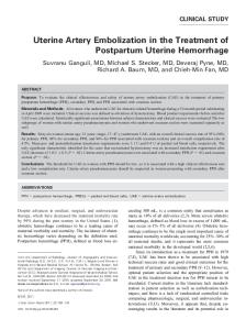
The mathematical model we proposed here considers the growth of a myoma embedded in a surrounding tissue. The spatial domain x ∈ Ω(t), bounded by a closed curve Γ∞ (x, t) = 0 (which could represent infinity), consists of a region occupied by the myoma x ∈ ΩM (t) and a surrounding tissue region x ∈ ΩT (t) = Ω(t)/ΩM (t), separated by a closed curve Γ(x, t) = 0. These regions are illustrated in Figure 1. In the absence of the myoma Ω = ΩT will be a fixed space, but the growth of the myoma within may deform it. We will assume the myoma has
3
Surrounding tissue n∞
Blood flow in pa = pa ∞
Ω T (t)
Myoma
Ω M (t) (1) φ (1) s φw φa φv
Γ∞ = 0
n
(2) φ (2) s φw φa φv
Γ=0
Blood flow out pv = pv ∞
Figure 1: Schematic of the model system. The domain is restricted by a closed (possibly infinite) surface consisting of the myoma ΩM (t) and surrounding tissue ΩT (t), separated by a closed interface given by Γ(x, t) = 0 (with outward normal n). Each region consist of cells (volume (i) (i) fraction φs , i = 1, 2), extracellular space (φw ), arteries/arterioles (φa ) and veins/venules (φv ). The volume fractions of the vasculature are assumed to be constant throughout, but that of cells and extracellular space may differ between the myoma and surrounding tissue indicated by the superscripts “(1)” and “(2)”, respectively. developed sufficiently to have its own blood supply, and that adequate nutrients for growth are present throughout. In this respect, myoma tissue is taken to be similar to normal tissue and we assume in the modelling that there is no significant difference between the blood supply of the two. The continuum approach requires that each control unit volume contains a sufficient number of cells and that the average properties immediately surrounding a point are taken to be the elastic properties of that point. The stress generated is therefore the average force per unit area between these adjacent ’particles’ each consisting a number of cells. Note that in addition to the description given in the text, the variables are also listed in Table 1. All space in both regions are assumed to be occupied by cells and collagen (combined volume fraction φs ), extracellular space (principally water, φw ) and vasculature (arteries φa and veins φv ). The separate treatment of arteries and veins distinguishes the current model to that of related vascular tumour models, which consider only a single vasculature phase [4, 16]; the benefits of doing this will be made clear after equation (2.5). There being no other material in the regions means that the sum of these fractions is equal to unity, i.e. φs + φw + φa + φv = 1.
(2.1)
In general the volume fractions will not be the same throughout the domain. In our assumption of the blood supply being similar in the two tissue types, we assume that φa and φv are constant throughout; in the absence of detailed histological data to suggest otherwise, this is a reasonable starting point. Implicit in this assumption is that as the myoma grows, new vasculature is being generated to maintain the constant volume fraction. However, the cellular densities may be different between the two tissues, but constrained by equation (2.1). As with the vascular volume fractions, we will assume, as a first approximation, that the volume fractions φs and φw (1) (1) are constant within the two tissues (but not necessarily equal), denoting them as φs and φw (2) (2) for myomas and φs and φw for the surrounding tissue. We note that φs accounts for both 4
Variable vs (x, t) vw (x, t) va (x, t) vv (x, t) pa (x, t) pv (x, t) pw (x, t) prs (x, t) ε(x, t) σ(x, t) S(x, t)
Representation solid phase velocity field water velocity field artery blood flow velocity field vein blood flow velocity field arterial fluid pressure venous fluid pressure extracellular fluid pressure reaction stress strain tensor in solid phase stress tensor in solid phase volume growth rate per unit volume
dimension length/time length/time length/time length/time force/area force/area force/area force/area none force/area time−1
Table 1: List of model variables.
living cells and collagen fibre and we assume that as cells grow collagen is being laid down at the same time, in such a way that the proportion of cells and collagen remains constant (we will henceforth refer to this phase as the “solid phase”). Under these assumptions, both the myoma and the surrounding tissue are therefore incompressible. We note that the superscript notation applies to all variables listed in Table 1 and parameters to distinguish between quantities inside and outside the myoma, however, in the discussion prior to Section 2.2 they will not be present in the formulation on the understanding that the same equations apply to all variables in both regions. Blood flow in the model is driven by the pressure difference between the arteries and veins on the boundary, namely pa∞ and pv∞ , respectively. These generate a flow with mean velocities va in the arteries and vv in the veins. We assume volume transfer from the arteries to the veins is proportional to the difference in pressure between arteries, pa , and veins, pv , to represent flow in the capillaries connecting them. We assume that fluid from the capillaries leaks into the extracellular space at a rate mutually proportional to the capillary flow rate (∝ (pa −pv )) and the difference between capillary blood pressure, ψ(pa , pv ) (assumed equal to the mean blood pressure, i.e. ψ(pa , pv ) = (φa pa + φv pv )/(φa + φv )) and extracellular fluid pressure, pw , in accordance with Starling’s law (assuming negligible osmotic pressure). The volume conservation equations for blood flow are thus φa ∇ · va = −α (pa − pv ),
(2.2)
φv ∇ · vv = α (pa − pv ) − α1 (pa − pv ) (ψ((pa , pv ) − pw ) ,
(2.3)
where α is the hydraulic conductivity coefficient and α1 the leakage rate constant, recalling that φa and φv are assumed constant. In order for tissue to grow, fluid is taken in from the environment to be converted into new cellular material. Let S be the volumetric cell growth rate per unit volume, then conservation of volume of the solid phase means that φs ∇ · vs = S,
(2.4)
where vs is the velocity of the solid phase. The function S will in general depend on many factors and is discussed further below. The absorption of extracellular fluid by the growing 5
cells and the volume gained from blood vessel leakage lead to the following volume conservation equation for the extracellular fluid phase, φw ∇ · vw = −S + α1 (pa − pv ) (ψ(pa , pv ) − pw ) .
(2.5)
The separate treatment of the arterial and venous phases means that the capillary flow rate (α(pa − pv )) and mean capillary pressure (ψ(pa , pv )) can be deduced naturally from the model. Furthermore, the nonlinearity in the vascular leakage term in equation (2.5) ensures that the proposed model is not invariant to changes in vascular pressure difference on the outer boundary, i.e. pa∞ − pv∞ ; consequently, the effect of factors, such as oestrogen, that alters the blood flow can potentially be predicted by the model (see Section 3.3). For simplicity we assume that growth, and hence new volume, occurs only in the myoma part of the domain, so that S = 0 in the surrounding tissue. Within the myoma we assume that S is a bounded, non-negative function such that S ∈ [0, Smax ], where Smax is the maximum growth rate of of the solid phase material. In many models describing tissue or tumour growth, it is assumed that the growth division of cells is dependent on a nutrient source, however, in myomas it seems reasonable to assume that they are well vascularised and nutrient limitation is not an issue, even in large myomas; features such as necrotic cores are absent in benign myomas [11]. Furthermore, S will in general be dependent on the availability of extracellular fluid to create new volume, but this is not a concern in the current model due to the assumption that φw is constant. However, the colonies are dense and it is well known from experimental studies that cell proliferation may be influenced by the feedback of the growth-induced stress (see, for example, Helmlinger et al. [15]). The feedback processes involved are complex (e.g. mechanotransduction within the cells) and a detailed description is beyond the scope of the present study. We will therefore adopt a simple, but representative, form in this study, namely, Smax x ∈ ΩM , Tr(σs )/3 + pw∞ > 0, Smax S = (2.6) , x ∈ ΩM , Tr(σs )/3 + pw∞ ≤ 0, 1 + |Tr(σs )/3 + pw∞ |m /σcm 0 x ∈ ΩT , where σs is the Cauchy stress tensor for the solid phase, Tr(σs )/3 is the mean normal stress, −pw∞ is the mean normal background environmental stress (discussed in Section 2.1) such that Tr(σs )/3 + pw∞ is the effective mean stress for material deformation. The modelling assumes that under normal conditions cells experience stress according to Tr(σs )/3 = −pw∞ , such that if Tr(σs )/3 < −pw∞ then cells are under compression and if Tr(σs )/3 > −pw∞ then they are under tension. In broad agreement with [15], the function S is chosen so that the growth rate will drop significantly under high compression, i.e. below a threshold stress Tr(σs )/3 + pw∞ < −σc , where σc is some critical stress level. Under tension, i.e. Tr(σs )/3 + pw∞ > 0, Tomasek et al. [34] noted that mechanical tension is a signal for tissue generation; however, it turns out that since the myoma is always growing (as S ≥ 0) the myoma cells are never under tension, so we have assumed S = Smax for simplicity. To describe the stress within myomas and the surrounding tissue, we use ideas stemming from mixture theory. This approach has been widely used to describe multi-phase interactions including that of tumour growth; see, for example, [1, 5] and the references therein. We assume that the relaxation timescales of the myoma constituents are much shorter than that of growth and we thus neglect inertia in our system. Hence, conservation of momentum leads to the following force balance equations for each of the four phases, 0 = ∇ · (φi σi ) + Fi , 6
(2.7)
where σi is the stress tensor for phase i, with i = a, v, s, w, and Fi is a body force. The system being in equilibrium implies that Fa + Fv + Fw + Fs = 0,
(2.8)
see, for example, [1, 16]. For the fluid phases, we adopt the usual assumptions for (Darcy) flow in a porous media, whereby the stress tensors reduce to σa = −pa I,
σv = −pv I,
σw = −pw I,
(2.9)
and the corresponding body forces account for the drag between the solid-fluid phases, hence φa va , ka φv vv , = pv ∇φv − kv φw = pw ∇φw − (vw − vs ), kw
Fa = pa ∇φa −
(2.10)
Fv
(2.11)
Fw
(2.12)
where the first term on each of the right-hand sides ensures that flow is generated only by pressure gradients; however, with the assumption that the φi s are piecewise constant in Ω, these terms are zero. The constants ki s are permeability coefficients that are in general dependent on the fluid properties, the permeability of the porous media and inversely related to the drag coefficients between the fluid-solid phases. Combining (2.7) and (2.9)-(2.12), leads to va = − ka ∇pa ,
vv = − kv ∇pv ,
vw − vs = − kw ∇pw ,
(2.13)
which are the Darcy’s law formulations for flow in a porous media. Using (2.7)-(2.9) we have the force balance for the solid phase ∇ · (φs σs ) = ∇ (φw pw + φa pa + φv pv ) .
(2.14)
The solid phase is viewed as an isotropic elastic solid that over a small time interval the elastic response is assumed to be locally linear. The proposed stress-strain relationship takes into account the stress generated by deformation and growth of the tissue. We assume that the stress generated in the vasculature is contained by the vessel walls and the environmental stress experienced by the solid phase is that of extracellular pressure, pw . The linear stress-strain relation is σs = − pw I + 2µ ε + λ eI − Kη I − prs I,
(2.15)
where I is the identity matrix. The first term on the right-hand side is the contribution to the stress from environmental pressure. The second and third are the stress generated by deformation, where ε is the strain tensor and e is the dilatation, defined as 1 ε = (∇u + (∇u)T ) 2
and e = ∇ · u,
where u is the displacement of the solid phase and µ and λ are Lam´e constants. The fourth term describes stress induced by volumetric cell growth, in which η is the strain induced per unit volume and K = 2µ/3 + λ is the bulk modulus; this term is analogous to modelling the thermal 7
expansion of materials (see Landau and Lifshitz [19]) and assumed in the tumour models of Jones et al. [18] and Roose et al. [31]. The final term, prs , is an arbitrary pressure that describes the reaction stress resulting from the incompressibility assumption, i.e. the volume fraction of the solid phase, φs , being piecewise constant. In general, prs cannot be prescribed and consequently tissue stress can only be determined using the force balance equation (2.14); see, for example, Spencer [32]. The stress-strain relation (2.15) is only valid for small strain over a small time interval and cannot be used to describe stress build-up over a prolonged period of continuous growth. As with related studies [18, 31], we evaluate this accumulated stress by differentiating the constitutive equation (2.15) with respect to time, noting, in particular, vs = ∂u/∂t [32]. The principal of material invariance requires the objectivity of the quantities in the resulting stress rate equation to be observed. There are many definitions for the time derivative that preserves objectivity, of which the Jaumann derivative is commonly used for the stress rate Dσs /Dt, defined as Dσs Dσs = + ω σs − σs ω, Dt Dt
(2.16)
where D/Dt = ∂/∂t + vs · ∇ is the material derivative and ω = −(∇vs − (∇vs )T )/2 is the second-order vorticity tensor (see, for example, Roose et al. [31] and Fowler and Noon [13]). We thus derive the stress rate equation from (2.15) as D σs D pw S D prs = − I + µ (∇vs +(∇vs )T ) + λ ∇ · vs I − K I − I, Dt Dt φs Dt
(2.17)
where it is assumed that Dη/Dt = S/φs . The function η defined in this way ensures that in the absence of any reaction stress, as in unrestricted tissue growth, the total normal stress σkk is not affected by tissue growth by virtue of equation (2.4); this is equivalent to thermal expansion of materials not leading to additional stress [19]. In the full three-dimensional problem there are twenty-two variables for each region, listed in Table 1, consisting of four velocities each with three components, four pressures and six components of the symmetric stress tensor σs , and there are twenty-two independent equations, namely (2.2)-(2.5), (2.13), (2.14) and (2.17), so that given appropriate boundary conditions (discussed in Section 2.2) the system of partial differential equations form a well-posed system. The fact that myomas tend to grow spherically will enable a substantial reduction of the system to be made, this being discussed in Section 2.3.
2.1
Non-dimensionalisation
Before we proceed to analyse the equations, it is convenient to write the equations in dimensionless form. The spatial variable x is scaled with a representative initial length-scale L and time is scaled with maximum myoma cell growth rate Smax , hence x = Lx ˆ,
t =
tˆ Smax
,
where the quantities with hats are dimensionless. For the simulations of Section 3, |ˆ x| = 1 and t = 1 represents about 2.5 mm and 1.5 years, respectively. The dependent variables are scaled as follows ˆa, v a = L α p0 v
ˆv , v v = L α p0 v
p∗ = p0 pˆ∗ + pw∞ ,
ˆs, v s = L Smax v
σij = − pw∞ δij + p0 σ ˆij , 8
ˆw, v w = L Smax v ˆ S = Smax S,
where, ∗ = a, v, w and p0 = pa∞ − pv∞ ,
pw∞ =
φa pa∞ + φv pv∞ = ψ(pa∞ , pv∞ ). φa + φv
Here, pa∞ and pv∞ are the far field arterial and venous pressures respectively, hence p0 is the farfield pressure difference, and pw∞ is the mean far-field fluid pressure in tissues (i.e. the weighted average of the arterial and venous pressures there). The constant p0 can be approximated by the mean arterial pressure of about 104 Pa. The parameters are rescaled accordingly, α1 p20 , µ ˆ = Smax ka kˆa = , kˆv = α L2 α ˆ1 =
µ ˆ λ σc ˆ = K, σ , λ = , K ˆc = , p0 p0 p0 p0 kv k p S w 0 max , kˆw = 2 , ξ = , α L2 L Smax α p0
where the last dimensionless parameter is the ratio of volume rate of water intake by growing cells and the volume rate of water flow in the blood; as cellular intake of water represents a very small fraction of the water flowing through the tissues it follows that ξ � 1. The hats of the rescaled variables and parameters are dropped in the following analysis for brevity. The dimensionless mass conservation equations are as follows φa ∇ · v a = −(pa − pv ),
(2.18)
φv ∇ · v v = (pa − pv ) − ξ α1 (pa − pv ) (ψ(pa , pv ) − pw ) ,
(2.19)
φw ∇ · v w = α1 (pa − pv ) (ψ(pa , pv ) − pw ) − S, φs ∇ · v s = S.
(2.20) (2.21)
In the remainder of the paper we will use ξ � 1 and simplify equation (2.19) assuming that ξ = 0. The remaining equations take the same form as before and are included here for completeness. The equations describing Darcy’s Law are v a = −ka ∇pa ,
(2.22)
v v = −kv ∇pv ,
(2.23)
v w − v s = −kw ∇pw ,
(2.24)
the force balance equation is ∇ · φs σs = ∇(φa pa + φv pv + φw pw ),
(2.25)
and the stress-strain rate equation is Dσs Dpw Dprs S = − I + µ(∇vs + (∇vs )T ) + λ∇ · vs I − K I − I. Dt Dt φs Dt The dimensionless form for the growth rate functions 1 �−1 S = 1 + (−Tr(σs )/3)m /σcm 0
9
(2.26)
is x ∈ ΩM , Tr(σs ) > 0, x ∈ ΩM , Tr(σs ) < 0, x ∈ ΩT .
(2.27)
2.2
Boundary conditions: general case
Let the surfaces Γ(x, t) = 0 and Γ∞ (x, t) = 0, shown in Figure 1, have outward unit normals n and n∞ respectively. These boundaries move with the local cellular velocity leading to the kinematic conditions, ∂Γ + vs Γ=0 · ∇Γ = 0, ∂t
∂ Γ∞ + vs Γ∞ =0 · ∇Γ∞ = 0. ∂t
At the interface the cellular material inside and outside the myoma must be moving at the same velocity, i.e. vs is continuous across the boundary. We also assume continuity of the pressures pa , pv and pw , extracellular fluid flux φw vw and the force normal to the interface, hence, (2)
(1)
(1) = v (2) , (2) vs (1) = vs (2) , φw vw (1) = φw vw (2) , va (1) v � = va , v�v (1) (2) (1) (2) (1) (2) (1) (2) pw = pw , pa = pa , pv = pv , n · Σ − Σ · n = 0,
Γ = 0:
(i)
(i) (i)
(i)
(i)
where Σ(i) = φs σs (i) −(φw pw +φa pa +φv pv )I, recalling that the volume fractions of arteries and veins are taken to be equal in both tumour and surrounding tissue regions. On the outer boundary given by Γ∞ = 0 (which could be at infinity), with outward normal n∞ , we impose Γ∞ = 0 :
(2) p(2) w = 0, pa =
φv φa , p(2) = − , n∞ · Σ(2) · n∞ = 0, v φa + φv φa + φv
where the conditions on pa and pv are derived following non-dimensionalisation and the latter conditions represent zero normal force on the outer boundary. Further boundary conditions depend on the specific setup, e.g. the location of origin. Initially, the regions will be contained within boundaries according to t = 0:
Γ(x, 0) = Γ(0) (x), Γ∞ (x, 0) = Γ(0) ∞ (x),
and initial conditions on the stresses to close equations (2.26).
2.3
Spherical geometry
By exploiting the spherical properties of myoma, the model can be significantly reduced. We assume the entire domain Ω is a sphere centred at the origin r = 0, where r ≥ 0 is the radial coordinate. The part of the domain occupied by the myoma (i.e. ΩM ) is assumed to be 0 ≤ r < R(t) and that for the surrounding tissue (ΩT ) is R(t) < r < R∞ (t), where the radii R(t) and R∞ (t) (in the finite-sized domain case) are moving boundaries. Assuming radial symmetry implies that displacement only occurs in the r direction, hence the angular velocities are all zero and the stress tensor σs reduces to the diagonal matrix σrr 0 0 0 , σs = 0 σθθ 0 0 σφφ where θ ∈ [0, π] is the polar angle and φ ∈ [0, 2π) is the azimuthal angle. Moreover, radial symmetry implies that the angular stresses are equal, i.e. σθθ = σφφ [8], and that the second-order vorticity tensor, w, in the Jaumann derivative in equation (2.16), is zero (i.e. D/Dt = D/Dt).
10
The radially symmetric forms of (2.2)-(2.5), (2.13) and (2.14) in spherical geometry are straightforward to derive using standard results. Explicit treatment of the arbitrary reaction stress, prs , can be avoided by subtracting the evolution equations (2.17) of σrr and σθθ , namely � � � � � � ∂ ∂ ∂vs S ∂ ∂ ∂vs vs σrr = − (pw + prs ) + 2µ −K , + vs + vs +λ +2 ∂t ∂r ∂t ∂r ∂r ∂r r φs � � � � � � ∂ ∂ vs S ∂ ∂ ∂vs vs σθθ = − (pw + prs ) + 2µ + λ −K , + vs + vs +2 ∂t ∂r ∂t ∂r r ∂r r φs where vs is the solid phase velocity in the radial direction, to obtain a single equation for a new variable σ ¯ = σrr − σθθ , see equation (2.32). Let v∗ be the other radial velocities for ∗ = w, a, v, then the full system of equations for the myoma and surrounding tissue, with the superscripts (1) and (2) absent for clarity, are φs ∂(r2 vs ) r2 ∂r φw ∂(r2 vw ) r2 ∂r
= S,
(2.28)
= −S + α1 (pa − pv ) (ψ(pa , pv ) − pw ) ,
(2.29)
∂pw , vw − vs = −kw ∂r � � 2 ∂pw ∂pa ∂pv ∂σrr φs + σ ¯ = φw + φa + φv , ∂r r ∂r ∂r ∂r � � ∂σ ¯ ∂σ ¯ ∂vs vs + vs = 2µ − , ∂t ∂r ∂r r
(2.30) (2.31) (2.32)
with S = 0 when r > R(t), and for the vasculature φa ∂(r2 va ) r2 ∂r φv ∂(r2 vv ) r2 ∂r
= −(pa − pv ),
(2.33)
= pa − pv ,
(2.34)
∂pa , ∂r ∂pv = −kv , ∂r
va = −ka
(2.35)
vv
(2.36)
where we have imposed ξ = 0, as discussed above, in equation (2.34). Combining equations (2.28)-(2.30) leads to the useful equation � � � � 1 ∂ 1 1 S 2 ∂pw 2 r − γ (p − p ) p = + − γ 2 (pa − pv ) ψ(pa , pv ), (2.37) a v w r2 ∂r ∂r k w φw φs where γ 2 = α1 /kw φw . We assume that the length-scale L in the non-dimensionalisation section is the initial radius of the myoma (we assume L ≈ 2.5 mm). The full set of initial and boundary
11
conditions are as follows t = 0:
R = 1,
r = 0:
vs
r = R(t) :
r = R∞ (t) (or ∞) :
(1)
0 , R∞ = R∞ (1)
(1)
= vw = va
σ ¯ (1) = σ ¯ (2) = 0, (1)
= vv
= 0,
(1) (2) (1) (1) (2) (2) (1) vs = vs , φ w vw = φw vw , v a = (1) (2) (1) (2) (1) (2) pw = pw , pa = pa , pv = pv , (1) (1) (2) (2) (1) (2) φs σrr − φs σrr = (φw − φw ) pw ,
p(2) w = 0,
p(2) a =
φv , φa + φv
p(2) = − v
(2)
(1)
va , v v
φa , φa + φv
(2)
= vv , (2.38)
(2)
σrr = 0,
and the moving boundaries satisfy dR = vs(1) (R(t), t), dt
dR∞ = vs(2) (R∞ (t), t), dt
(2.39)
the latter being relevant for R∞ < ∞. We note that in the last condition imposed on the r = R(t) interface, we have used continuity of pi and φj , for i = w, a, v and j = a, v, to derive the force balance. The initial condition σ ¯ = 0 implies that at the initial state the material is evenly stressed in all directions. The growth rate is given by 1 r < R(t), σkk > 0, � m m −1 S = (2.40) 1 + (−σkk /3) /σc r < R(t), σkk < 0, 0 r > R(t), where σkk = Tr(σs ) = 3 σrr − 2 σ ¯. We note that a positive right-hand side to (2.29) means that the fluid is seeping out of the vasculature at a faster rate than that being used in the growth of cells. In the limit of zero blood pressure difference, i.e. pa − pv = 0, then using (2.28), (2.29) and (2.38), we have vw = −φs vs /φw < 0 (since S ≥ 0); here, the extracellular fluid is being “passively” drawn in from the surrounding tissue. This is the situation in all avascular growth models in which extracellular fluid transport is explicitly considered and mass is conserved, e.g. [5, 8, 31]. The balance between vascular and passively sourced extracellular fluid is discussed in Section 3. The reduced system consists of nine variables for each region and two more in R(t) and R∞ (t); there are altogether twenty boundary and initial conditions in (2.38) and hence we expect the system (2.28)-(2.40) to be well-posed. 2.3.1
Analytical solution of vascular equations
The vascular equations (2.33)-(2.36) and boundary conditions (2.38) form a closed system. For the finite sized domain case, R∞ < ∞, we can deduce the conserved quantity φa ka pa + φv kv pv =
φa φv (ka − kv ) , φa + φv
and the differential equation for p¯ = pa − pv , � � 1 ∂ ¯ 2 ∂p r − δ 2 p¯ = 0, r2 ∂r ∂r
12
(2.41)
where δ 2 = (φa ka + φv kv )/(φa φv ka kv ), subject to ∂ p¯/∂r|r=0 = 0 and p¯(R∞ , t) = 1; which on solution gives p = pa − pv =
R∞ sinh(δ r) , r sinh(δ R∞ )
(2.42)
leading to �
� φv R∞ sinh(δ r) β+ −β , φa + φv r sinh(δ R∞ ) � � R∞ sinh(δ r) φa +β , β− φa + φv r sinh(δ R∞ ) � � φv R∞ (sinh(δr) − δr cosh(δ r)) β− , φa + φv r2 sinh(δ R∞ ) � � R∞ (sinh(δr) − δr cosh(δ r)) φa β+ , φa + φv r2 sinh(δ R∞ )
pa = pv = va = vv =
(2.43) (2.44) (2.45) (2.46)
where β =
φa φv (ka − kv ) , (φa + φv )(ka φa + kv φv )
recalling that φa and φv are taken to be identical for both tumour and surrounding tissue regions and similarly are ka and kv . On an infinite domain, i.e. R∞ = ∞, bounded solutions are not possible. The limits ka → ∞ and kv → ∞, i.e. negligible drag in the vessels, lead to uniform presure distribution pa ≡ pa (∞) and pv ≡ pv (∞), but with va → −∞ and vv → ∞ as r → ∞. For this case we will neglect the flow velocities, and assume pa ≡
φv , φa + φv
pv ≡ −
φa , φa + φv
(2.47)
which represents a situation in which the entire domain has a uniform capillary network with an even blood supply throughout. We note for this case, equation (2.29) reduces to φw ∂(r2 vw ) r2 ∂r
= −S − α1 pw ,
(2.48)
and (2.37) reduces to 1 ∂ r2 ∂r
� � � � S 1 1 2 ∂pw 2 r − γ pw = + , ∂r k w φw φs
(2.49)
recalling that γ 2 = α1 /kw φw . 2.3.2
Analytical solutions for r > R(t)
In this region S ≡ 0, so equation (2.28) integrates to give vs(2)
. RR 2 = , r2 13
(2.50)
. . . 2 , hence where R = dR/dt. In the finite domain case, R∞ = RR 2 /R∞ 3
3 0 R∞ − R∞ = R 3 − 1,
(2.51)
which states that the change in volume of the entire domain volume is equal to the volume change in the myoma, as expected. Equation (2.32) becomes . . 2 ∂σ ¯ (2) RR 2 ∂ σ ¯ (2) (2) RR , + = − 6 µ ∂t r2 ∂r r3 subject to σ ¯ (2) (r, 0) = 0 and R(0) = 1, which, using the method of characteristics, solves to give � � R3 − 1 (2) (2) σ ¯ = 2 µ ln 1 − . (2.52) r3 Integrating equation (2.31), using (2.52), leads to (2)
(2) σrr =
φw
(2)
φa (2)
pa +
φv (2)
pv +
� 4 µ(2) 3 dilog((R 3 −1)/R∞ ) − dilog((R 3 −1)/r 3 ) ,(2.53) 3
φs φs Rx where dilog(x) = − 0 ln(1 − w)/w dw is the dilogarithm (or Spence’s function), such that dilog(0) = 0 (relevant for R∞ → ∞) and dilog(1) = π 2 /6.
3
φs
p(2) w +
Numerical Simulations
The simulations to follow are the combination of the numerical solution of equations (2.28)-(2.32) and (2.38) and the analytical solutions (2.43), (2.44) and (2.52). For ease of computation, the myoma and surrounding tissue regions were mapped onto the unit interval using r = R(t)ρ and r = R(t) + (1 − ρ)(R∞ (t) − R(t)), respectively, so that in both regions the coordinate r = R(t) is mapped to ρ = 1. We rescale all the variables and boundary conditions accordingly, where we note in particular the stress rate equation (2.32) for r < R(t) becomes ! ! (1) (1) (1) ∂σ ¯ (1) vs R˙ ∂σ ¯ 2µ ∂vs vs + − ρ = − , (3.54) ∂t R R ∂ρ R ∂ρ ρ where R˙ = dR/dt. The equations were solved using a time-step adaptive, predictor-corrector scheme incorporating the Numerical Algorithms Group (NAG) routine D02RAF (a boundary value solver) to solve simultaneously equations (2.28)-(2.31), an implicit second-order accurate hybrid scheme (the same as that used in [36]) for equation (3.54) and the trapezium rule for R(t). The dilog function was approximated using NAG routine D01AJF (an integration routine that is able to handle logarithmic singularities). To simulate the infinite sized domain case, the surrounding tissue region was truncated, at r = RT say, where the analytical solutions of Section 2.3.2 were used to the generate boundary conditions there and, by solving (2.49) (2) (with S = 0 and using pw (∞, t) = 0), closure of the numerical problem was achieved via the (2) (1) relationship pw (RT , t) = pw (R, t) e−γRT /RT . The solutions of the equations often evolve to form a boundary layer at ρ = 1 and a contracting spatial mesh was used such that ρi+1 − ρi = ν(ρi − ρi−1 ), where ν < 1, which enabled the simulations to run for large time using fewer mesh 14
Parameter 0 R∞ (1) µ , µ(2) m σc ka kv (1) (2) kw , kw α1 φa φv (1) (2) φw , φw (1) (2) φs , φs
interpretation initial coordinate of outer boundary Lam´e constant exponent of the growth function critical stress threshold permeability constant for the arteries permeability constant for the veins permeability constant for extracellular fluid transport coefficient between vasculature and fluid arterial volume fraction venous volume fraction extracellular fluid fraction cell volume fraction
values 30 10 60 21.1 104 104 0.05 0.1 0.05 0.05 0.05 0.85
Table 2: Table showing the standard values of the dimensionless parameters used in the simulations. The derived parameters are δ ≈ 0.0632, β = 0 and γ ≈ 2.282 and since ka = kv then the mean capillary pressure is given by ψ(pa , pv ) = 0 from equation (2.41). See Section 3.1 for a discussion on these parameters. In the simulations presented, t = 1 represents about 1.5 years, r = 1 about 2.5 mm and 1 unit of stress or pressure is about 104 Pa. points. For shorter simulations 200 points were sufficient, whilst for the longer runs up to 3000 points were used. The values of the parameters used in the simulations below are listed in Table 2, unless stated otherwise, and are discussed in Section 3.1. An important factor concerning myoma growth as predicted by the model are the two ways in which extracellular fluid is supplied to the tissue. These two ways are: (1) Seepage from vasculature into the extracellular fluid. This will be referred to as “vascularinflux”. (2) Extracellular fluid drawn in “passively” from the surrounding tissue. This will be referred to as “passive-influx”. We will first present the standard simulation of the non-dimensionalised system and then discuss the effects of the surrounding tissue, vascular efficiency and sources of extracellular fluid on growth.
3.1
Standard simulation
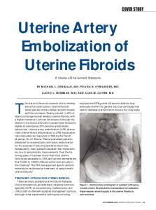
Very small myomas (of size 1-3 mm in diameter) are usually avascular and, by about 4 mm in diameter, blood vessels begin to invade from the periphery and infiltrate deep into the myoma (see for example [35]). We assume in the simulations to follow that the myoma is fully vascularised from the start and that the initial radius of R(0) = 1 represents about 2.5 mm, within a surrounding tissue of about 75 mm (R∞ (0) = 30). As discussed in the introduction, Mavrelos et al. [25] used clinical data to show that small (< 20 mm in diameter) and large myomas (> 50 mm in diameter) develop at a faster rate (volume growth of 51.3% and 40% in a year, respectively) than those in between (volume growth of 16.8% in a year). This data suggests that growth between 4-20 mm will be about 12 years and between 20-50 mm will be about 18 years, whereby the combined total of about 30 years covers nearly the entire reproductive period in women. 15
14
3 myoma growth rate (dR/dt )
myoma radius (R )
12 10 8 6 4 2 0
0
5
10 time (t )
15
2.5 2 1.5 1 0.5 0
20
0
5
10 time (t )
15
20
Figure 2: Evolution of the myoma radius R(t) and the growth rate dR/dt for the “standard simulation”, noting that t = 1 is approximately 1.5 years and R = 1 represents a radius of about 2.5 mm. Parameters listed in Table 2. There is considerable variation in this data and our aim in selecting the parameters in Table 2 is to produce results that (1) reproduce qualitatively the fast-slow-fast growth pattern in myoma, (2) ensure water in the core of the myoma is mostly sourced from the vasculature (i.e. the right-hand side of (2.29) is positive at r = 0) and (3) are sensitive to blood pressure variations (reflecting the effect of sex hormones on blood supply). On account of the variability of data in [25] and the simplifying assumptions used in the model, we do not expect the parameters to be definitive. The value µ = 10 corresponds to an elastic modulus of about 105 Pa, which is 3-4 times that of the hardest (soft-tissue) solid tumour listed in Netti et al. [27]. As necrotic regions are not usually observed in myomas, the vasculature parameters are chosen to make δ � 1, so that, whilst the myoma is of a biological relevant size, the vascular pressure difference pa − pv = O(1) over the whole of the region. We note that we have prescribed a large value to the exponent m in equation (2.40), reflecting a consistent level of growth whilst −σkk /3 < σc and negligible growth when experiencing high compressive stress, i.e. −σkk /3 > σc . In Figure 2, we show the evolution of the radius R and growth rate dR/dt using the standard parameter set of Table 2. As desired, we obtain qualitatively the fast-slow-fast phases of growth as observed in [25], where the second fast phase commences when R ≈ 10, corresponding to a myoma of diameter of about 50 mm. We will refer to these three growth phases as Phase 1, 2 and 3, respectively. In the early stages (Phase 1), the stress levels, σkk , are sufficiently small (Figures 3) so that it has negligible impact on growth and hence the volume growth rate S ∼ 1 throughout the myoma region; this continues to be the case until −σkk /3 ≈ σc due to the exponent m in (2.40) being large. This low initial stress is due to small myomas causing only a small displacement, and hence stress, in the surrounding tissue. However, as can be observed from Figures 3, the resistance by the surrounding tissue to growth of a “medium-sized” myoma leads to stress building up to the threshold level σc , causing retardation of growth (Phase 2). Eventually, the myoma reaches such a size that the surrounding tissue becomes sufficiently thin so that it is no longer able to impart adequate resistance to restrict growth, consequently in time the magnitude of the stress in the myoma will drop significantly and the growth rate will return to an unconstrained level (Phase 3), where S ∼ 1. We note from the right-hand plot of Figure 4 that throughout the time period of the simulation the vascular pressure difference drops from pa − pv = 1 to about 0.6 over the domain, and consistently about 0.6 in the myoma. The effects
16
0
100 80 )
-5
azimuthal stress (
radial stress (
rr )
60 -10 -15 -20 -25
40 20 0 -20
0
5
10
15 20 distance (r )
25
30
-40
35
0
5
10
15 20 distance (r )
25
30
35
Figure 3: Dimensionless stress profiles at time t = 2 (solid curve), 5 (dashed curve), 10 (dotted curve) for the standard simulation. See Table 2 for parameter values and its caption for the scale in dimensional terms. arterial and venous pressure (pa, pv )
5
fluid pressure (pw )
0 -5 -10 -15 -20 0
5
10
15 20 distance (r )
25
30
35
0.4 0.2 0 -0.2 -0.4 0
5
10
15 20 distance (r )
25
30
35
Figure 4: Dimensionless extracellular fluid pressure distribution pw (left) and the distributions of arterial and venous pressures pa and pv (right) at times t = 2 (solid curve), 5 (dashed curve), 10 (dotted curve) from the standard simulation. See Table 2 for parameter values and caption for scale. Note that the arterial and venous pressures at the various time shown are almost identical but the interface between the myoma and the surrounding tissue, marked out by the diamonds, move outwards as time increases. of the vasculature will be discussed further in Sections 3.3 and 3.4. If growth was allowed to continue, the model predicts a further growth phase when myomas reach sizes well beyond that which is relevant biologically, where pa − pv drops to negligible levels (this is discussed in Section 3.5). The stress being negative within the myoma, as can be seen in Figure 3, is to be expected as growth continuously causes compressive stress between cells. We note in this simulation that (1) (1) within the myoma σ (1) ≈ 0 (not shown) so that σrr ≈ σθθ , i.e. cells within the myoma are experiencing uniform stress from all directions. In contrast, the non-growing surrounding tissue is compressed in the r direction by the growing myoma, but is stretched (hence, experiencing tensile stress) in the angular directions. The tensile force will in fact continue to build up and, (2) (1) from (2.52) and (2.53), we see that σθθ (R, t) → ∞ as R → ∞. The distribution of σrr attains 17
0.9
0.5
0.8 fluid velocity (vw )
cell velocity (vs )
0.7 0.6 0.5 0.4 0.3
0
-0.5
-1
0.2 0.1 0
0
5
10
15 20 distance (r )
25
30
-1.5
35
0
5
10
15 20 distance (r )
25
30
35
Figure 5: Distribution of dimensionless cell (left) and fluid velocity (right) at time t = 2 (solid curve), 5 (dashed curve), 10 (dotted curve) for the standard simulation. See Table 2 for parameter values and caption for the scale. its minimum around t = 11, before the rapid growth resumes as the stress subsides. The plots in Figure 4 show the distribution of extracellular pressure (left) and vascular pressure (right) at various time points. Initially, rapid growth leads to high consumption of extracellular fluid to produce new cells, that generates high negative pressure in the myoma core. As growth slows in Phase 2, the pressure subsides as growth slows (t = 5 and t = 10 curves in the Figure), which then builds up again as rapid growth resumes in Phase 3. The sources of extracellular fluid, i.e. from the vasculature or being drawn in from surrounding tissue, are investigated in Section 3.4. Figure 5 shows the distribution of cell velocity (left) and extracellular fluid velocity (right) at times t = 2, 5 and 10. As shown in Figure 3, the stress distribution, and consequently the growth rate S (not shown), are fairly uniform throughout the myoma, so the cell velocity vs is approximately linear for r < R (which makes the right-hand side of (2.32) small, leading to σ ≈ 0) and decays according to (2.50) for r > R. All of the profiles of vw are qualitatively similar and show, except in the vicinity of the interface at r = R, that extracellular fluid is generally flowing away from the myoma centre. In the core of the moyoma at t = 2, the demand for fluid for cell growth volume is met by the vasculature (i.e. vascular-influx dominated, we note vw ≥ 0 there), however, in the interface region, extracellular fluid is being drawn in from the surrounding tissue (passive-influx) at a sufficient rate to dominate that from blood flow (hence vw < 0). As r increases into the surrounding tissue the effect of myoma growth subsides, and since in this region pw ∼ 0 then from (2.30) vw ≈ vs .
3.2
Effect of surrounding tissue on growth
In the standard simulation, the surrounding tissue imparts a resistive stress that reduces the rate of growth during Phase 2. This continues until the surrounding tissue becomes sufficiently thin and its ability to impart stress subsides and growth moves into Phase 3. We thus expect thickness of this tissue to have a significant effect on growth after Phase 1. This turns out to be the case as is illustrated in Figure 6. We note that R∞ (0) = 30 corresponds to a diameter of 15 cm, which is approximately the dimension of the pelvic cavity. The figure shows that increasing R∞ (0) has the effect of reducing the duration of Phase 1, and slowing the growth and extending the duration of Phase 2. We note that the vascular pressure difference will be higher in 18
14 0
0
R = 20
12
R = 30
myoma radius (R )
0
R = 40
10 8 6
R 0 = 100
4 2 0
0
5
10 15 time (t )
20
25
Figure 6: Evolution of myoma radii, R(t), for various initial surrounding tissue sizes, namely 0 = 20, 30, 40 and 100. The standard simulation corresponds to R0 = 30, and all R∞ (0) = R∞ ∞ other parameters are listed in Table 2. 30
30 ka / kv = 106 /
=3 25
=1 myoma radius (R )
myoma radius (R )
25 20 15 10
= 1/3
20 15 10
5
5
0
0 0
5
10 15 time (t )
20
25
ka / kv = 104
ka / kv = 103 ka / kv = 102 / 0 0
5
10 15 time (t )
20
25
Figure 7: Dependence on parameters governing vascular flow and efficiency on the evolution of myoma radii, R(t). On the left, the effect of the far-field vascular pressure difference is shown for the given factors Ψ. Shown on the right the effect of vascular permeability ka = kv on growth. All the other parameters are listed in Table 2 and those adjusted by the factor Ψ are listed in Table 3. myomas surrounded by a thinner tissue, which contributes partly to the enhancement of growth rate. By allowing growth to continue beyond biologically relevant constraints, the solutions will eventually settle to the Phase 4 profile discussed in Section 3.5. Note that larger surrounding tissues result in higher stress levels leading to smaller tumour sizes; this is in good qualitative agreement with the predictions of other tumour growth models [8, 31] (albeit avascular growth) as well as experimental observations [15].
3.3
Effect of blood flow on growth
Sex hormones, such as oestrogen, are believed to play a major role in the growth of myomas [12, 24, 28, 29]. The presence of oestrogen induces vesodilation leading to an increase in blood flow maintaining nutrient supply to the myoma cells [29]. In menopause, without the sustained oestrogen production, myomas cease to grow and often shrink in sizes [12]. This is exploited in 19
Parameter µ(1) , µ(2) σc (1) (2) kw , kw α1
values (Ψ = 1) 10 21.1 0.05 0.1
values (Ψ = 3) 3.3 7.03 0.15 0.9
values (Ψ = 0.3) 33.3 70.3 0.015 0.009
Table 3: Adjusted parameter values corresponding to vascular pressure difference factor Ψ. the treatment of myomas, where gonadotropin-releasing hormone (GnRH) agonists are used to reduce oestrogen production, thereby causing myoma shrinkage and facilitating their surgical removal. Although, oestrogen is not considered in the current model, we can simulate its effects by altering flow characteristics of the blood. We will investigate two ways in which this can be done, firstly effecting the far-field pressure difference (p0 = pa∞ − pv∞ in dimensional terms), reflecting a change in flow into the uterus, and secondly effecting the extent of permeability of the vessels in the uterus (parameters ka and kv ). Due to the way the system was non-dimensionalised, an adjustment of p0 affects the dimensionless values of a number of parameters. More specifically, if we set p0 7→ Ψp0 , where Ψ is a dimensionless factor, then the relevant dimensionless parameters are affected as follows, µ 7→ µ/Ψ, α1 7→ Ψ2 α1 , kw 7→ Ψkw and σc 7→ σc /Ψ. The modified values used in the simulations shown in Figure 7 are listed in Table 3. It would be expected that decreasing Ψ would slow myoma growth and this is observed in the figure. The Phase 1 of growth is relatively unaffected by Ψ, but the timescale of Phase 2 is extended as Ψ decreases. The similarities in Phase 1 is due to the choice of the growth function S being a function of stress only, which is constant until Phase 2 begins. The reason for the differences in results here is due to the nonlinearity of equation (2.29) leading to the nonlinear scaling of α1 in terms of Ψ. We note that the role of nutrients is not considered in the current model and a reduced blood supply will mean a reduction in nutrients and probably the growth rate as well (though the lack of necrosis in most myomas suggests that they are seldom nutrient limited). An increase of the vascular permeability constants ka and kv would have the expected effect of enhancing growth and this is indeed shown to be the case in the right of Figure 7. Over a biologically relevant timescale, the most dramatic effects are observed for values of ka = kv ∈ (102 , 106 ). Growth using permeability values of ka = kv = 102 or less (or equivalently δ & 2) is indistinguishable from the avascular case (corresponds to ka = kv = 0); here, the pressure difference drops down to near zero close to the edge of the surrounding tissue, resulting in pa − pv ∼ 0 throughout the myoma. For ka = kv = 106 or more (equivalently δ . 0.0063) the growth follows more-or-less that of ka = kv = ∞; however, the solutions will eventually diverge as R increases and the pressure difference drops to zero in the core.
3.4
Vascular versus passive influx in myomas
The right-hand side of equation (2.29), namely F = −S + α1 (pa − pv )(ψ(pa , pv ) − pw ), describes the local rate of change of fluid volume. If the predominant extracellular fluid source is via vascular influx then this function will be positive, whilst negativity would suggest that passive influx is the dominant source. We are not aware of any detailed quantitative experimental study of the source of extracellular fluid in tissues, but under normal circumstances, it is likely that in vascularised myomas, fluid would mostly be sourced via vascular influx; which was assumed in the choice of standard parameters in Table 2. In this section we investigate the effect of some 20
100
1000
10 1
V
V
0.1
P
0.01
0.01 1
10
100
1000
V
0.05
0.001 0.1
P
0.15
1 0.1
0.1
0.001 0.01
0.2
10
P
kw
1
0.25
100
0.0001 0.001 0.01 0.1
R
1 R
10
100 1000
0 0.1
1
10 R
100
1000
Figure 8: Bifurcation diagrams in parameter-R space, showing regions in which the source of water in the myoma is vascular-influx dominated (labelled V) and passive-influx dominated (labelled P), for myomas growing at a maximum rate (i.e. S ≡ 1 in the myoma region). The lines marks the path ∂vw /∂r = 0 at r = 0 in kw −R (left), α1 −R (middle) and δ−R (right) space, where in each case all other parameters are fixed. The biologically relevant regions correspond to R . 20. The � symbols indicate the points corresponding to the values presented in Table 2. of the parameters on the dominant source of extracellular fluid. To simplify the analysis we focus on the case when S ∼ 1, which means that the analysis is directly relevant for growth (1) (2) (1) (2) Phases 1 and 3 and we also assume φw = φw and kw = kw , as is the case of the parameters in Table 2. In avascular myomas and tumours extracellular fluid transport is entirely through passive influx, and a simple definition to describe the transition point between passive- and vascular-influx dominated flow is when F = 0 at r = 0. The reduced system and the method of solution used is presented in Appendix A. The plots in Figure 8 show the bifurcation curves that separate the regions in parameter-R space between vascular-influx and passive-influx dominated flow (as defined above) sources of extracellular fluid at r = 0. We recall that the constant kw is the permeability coefficient, which encompasses porosity of media and is inversely related to the drag between fluid-solid phases. In the region of R . 20 the resistance to passive-influx is reduced as kw increases, meaning that 0 (R) > 0 on the bifurcation curve). However, as R fluid is able to penetrate deeper (hence kw increases beyond 20, the vascular pressure difference decreases becoming exponentially small at r = 0; so along the bifurcation the reduced effectiveness of blood supply is compensated by a reduction in permeability. For small myomas it is easy for fluid to be transported throughout via passive-influx, so the vessels need to be very leaky (i.e. large α1 ) in order for vascular-influx to dominate, however, as R increases (up R . 20) the passive transport is effected more by drag and so the leakage rate can be reduced. Once again, for R & 20, the decrease in blood flow means that to compensate the vessels must be increasingly leaky as r increases. In fact the the first two curves are directly related since the system derived in Appendix A is invariant under the transformation pw 7→ Υ−1 pw , α1 7→ Υα1 and kw 7→ Υkw , for any Υ ∈ /{0}. It follows that along the bifurcation curve F (α1 /kw ) = R, where F is some function, and is the reason for the apparent horizontal symmetry in the shape of the first two curves. The � symbols denote the points on the bifurcation curve corresponding to the data in Table 2, the left-hand one being of biological relevance (i.e. R . 15 − 20); we note that the initial condition of R = 1 lies in the region V. The parameter δ is inversely related to the permeability of the myoma’s vasculature. The data values of Table 2 give δ ≈ 0.06 so that for R = 10 the vascular pressure difference at r = 0 is about 57% of the maximum at the r = R∞ boundary, reducing to 10% when R ≈ 69. For R . 0.73, fluid transport is dominated by passive-influx, whilst in 0.73 . R . 10 the reduction
R
21
of extracellular fluid permeability means that, for small enough δ, vascular-influx will dominate. For R & 10 the efficiency of blood-flow must increase in order to compensate for increase in myoma size, hence the descent of the bifurcation curve.
3.5
Long time behaviour
Further insights into the behaviour of the model solutions can be gleaned from examining them in large time. Such solutions perhaps have no direct relevance biologically, as myomas will not be permitted to grow for so long, but they do indicate which particular mechanisms are most important in each of the growth phases discussed above. The plot of the growth rate in Figure 2 is extended in the left of Figure 9 to t = 100. The circled numbers in the figure are labels for the growth phases, the first three of which already discussed in Section 3.1. Phases 1 and 3 are (1) characterised by low levels of stress within the myoma so growth is given by R ≈ R[∗] e t/3φs where R[∗] is a constant (R[∗] = 1 in Phase 1). Phases 2 and 4 are more interesting. The intermediate growth phase, Phase 2, is a period in which the surrounding material becomes stretched and stressed by the growing myoma, but being considerably larger than the myoma at this stage it is able to impart stress that has the effect of reducing S(σkk ) in the growing region. In Appendix B, we analyse the model in an extreme version of this scenario, in which the surrounding tissue is extended to infinity, i.e. R∞ = ∞, the vascular pressure difference is set to pa − pv = 1 throughout the domain (see Section 2.3.1) and we seek solutions in the limit R(t) → ∞. This limit of the model is a reasonable approximation to the full one provided R/R∞ � 1 and pa − pv is approximately constant in the myoma. For large R, the analysis shows that the stresses imparted by the surrounding material are constant at leading ∗ , where σ ∗ is the solution to equation (B.17). order over most of the myoma, namely σkk ∼ σrr rr Consequently, S is constant at leading order and therefore growth is exponential, such that ∗ )/3φ(1) as R → ∞. The right plot in Figure 9 shows the evolution of Θ in ˙ R/R = Θ ∼ S(σrr s time, where the predicted large-time value is indicated by the dashed line. In Phase 4, the vasculature pressure difference in pa − pv is exponentially small across most of the myoma as R → ∞, and it is only in the rim region, where R −r = O(1/δ), is the difference of O(1) size. In the absence of vasculature, the only source of fluid in the core of the myoma is via passive-influx, and in large myomas that leads to an ever increasing build up in extracellular fluid pressure and consequently stress from the force balance equation (2.31). In Appendix C, term balancing arguments is used to show that growth evolves according to R ∼ R[4] t(m+1)/2m , as t → ∞, where R[4] is a constant. In the case of Phase 4 growth shown in the left of Figure 9, we obtain R ∼ R[4] t 61/120 , however, this large time solution takes a very long time to emerge in the simulation (see Appendix C).
4
Conclusion
The relatively simple structure and geometry of myomas are desirable properties for mathematical modelling, since the simplifying assumptions that are commonly used to reduce the more complex tumour models (e.g. spherical symmetry and isotropy) are well suited to myomas in vivo. The absence of necrosis [11], even when they are large, suggest that the vasculature functions well in myomas, unlike most other large solid tumours. This is most likely due to the slow 22
myoma growth rate (dR/dt )
70
0.4
60
0.35 0.3
50
0.25
3
40
0.2 30
0.15
20
0.1
1
10 0
0
0.05
4
2 20
40
60
80
0
100
time (t )
0
10
20
30 time (t )
40
50
60
Figure 9: Results of long time simulations. The left-hand figure is the same as that in Figure 2 with time extended up to t = 100; the four phases as discussed in the text are indicated by ˙ the circled numbers. The right hand plots shows the evolution of Θ = R/R for the infinitesized domain case (solid) and the leading-order large-time estimate (dash) as determined in the Appendix B. growth of myomas (over 15-25 years), allowing for a more robust vascular system to develop. On account of the hard, elastic nature of myomas, we modelled this using a solid mechanics approach to describe the effects of stress on myoma growth within a surrounding tissue. As a first approximation, we have assumed isotropy of the material and that the volume fractions of all components are constant within the myoma and the surrounding tissue. We proposed a simple linear stress-strain relationship, which, on differentiation with respect to time, was made applicable to an evolution problem with accumulated stress. Coupled to this we modelled fluid flow in the blood and extracellular space using standard approaches for modelling flow in a porous media; in particularly, we treated separately arterial and venous flow, which distinguishes this model to those studied in [4, 16]. Since the growth of myomas requires the conversion of extracellular fluid into cellular material, the fluid transport within myomas plays a major role in their growth; the current model considers two fluid sources, which we termed “vascular-influx” and “passive-influx”. The fast-slow-fast growth pattern of myoma growth, as described by Mavrelos et al. [25], was captured by the model (described as growth Phases 1, 2 and 3). Nutrient limitation is unlikely to be the only cause of this, as necrosis is largely absent in myomas. Our model suggests that this growth pattern can be explained by the combination of (1) stress build-up through myoma growth and resistance by the outer tissue and (2) the near cessation of cell growth in high compressive stress conditions. Initially, stress is low and hence growth is unhindered due to negligible displacement in the surrounding tissue (Phase 1), but when the displacement becomes non-negligible, it imparts stress that builds up in the myoma causing the slowing of growth (Phase 2), until the surrounding tissue is stretched sufficiently thin so that its ability to resist growth subsides and growth is able to accelerate once again (Phase 3). We note that in order for these growth phases to be visibly distinct as they appear to be clinically, there needed to be a sharp transition around a critical stress level σc in the growth function S. The explicit treatment of vascular transport in the model provides a number of insights into the extracellular fluid flow in myomas. When myomas are small and avascular (< 2 − 3 mm in diameter), flow is dominated by passive-influx of fluid from the surrounding tissue. However, the
23
balance shifts to dominance via vascular-influx for larger myomas (> 5 mm in diameter). Whilst vascular-influx is effective, the analysis of Section 3.5 showed that growth will be exponential, maximally fast in Phases 1 and 3 (due to S ∼ 1 in the myoma) and much slower in Phase 2. Although not relevant for myomas in clinical terms, but would be the case for most other large solid tumours, a collapse in blood flow in the core of the myomas leads to power-law growth (Phase 4). Of course, the collapse in blood flow means that the delivery of nutrients and oxygen ceases and necrosis will develop, a feature the current model is not set up to predict. The parameters used in the simulations were chosen to produce results that resemble the observed characteristic growth pattern of myomas. We made informed guesses for the volume fraction parameters, but there is very little data available to improve our estimates of the other parameters. The surgical removal of myomas is very common and there is potentially no shortage of samples that could be used for ex vivo experiments; for example, to determine more precisely the volume fractions, the permeability of the blood vessels (e.g. obtain estimates for vascular porosity and tortuosity), hydraulic conductivity of the non-vascular phases and the material properties of a myoma (e.g. estimates for the Lam´e constants µ and λ). From our numerical experiments, we found that the model results are qualitatively robust to parameter changes, and only quantitatively sensitive to changes in µ, σc and m (not shown). This sensitivity is due to the term −σkk /3σc in S being raised to a large power m (being necessarily large to induce near cessation of growth under sufficient compressive stress), so that the effects of small changes in the stress related parameter values are somewhat magnified. We note that our choice of function S was to agree in simple terms the qualitative description of stress-inhibited growth in [15] and there is scope for refinement in our future work (see below). Described in this paper is a first attempt to model uterine myoma growth. This model forms the foundation of future work investigating the interplay of factors, such as hormones and environment, on myoma growth and how these factors can be manipulated to best control it. As a pre-surgical treatment, the size of myomas are reduced using gonadotropin-releasing hormone (GnRH) agonists, which has the effect of reducing oestrogen production and, in turn, reduces blood flow into the uterus. Typically, the myoma shrinks to about half in size over a three month period [10, 14]. Interestingly, following the termination of treatment, if the shrunken myomas are not removed they will grow back to the original size within about 6 months, i.e. in a much shorter time than it took to grow the same volume before treatment [10, 14]. Though the model qualitatively predicts the action of oestrogen (Section 3.3), it will not be able to predict volume reduction by this treatment due to the constraint S ≥ 0, meaning that the myoma can only increase in size. What causes the initial shrinkage and relatively rapid regrowth is unclear, but the absence of necrosis suggests that cell death is not likely to be the only cause. We will be investigating plausible mechanisms for this. Further modelling extensions will be to relax the fixed volume fraction assumption and allow for inhomogeneities in the material. This will enable the consideration of other plausible growth effecting mechanisms, such as contact inhibition, that will lead to a refinement of growth function S. Many, but not all, myomas are enclosed in fibrous capsules, which will undoubtedly effect growth and the stress within; this may require the separation of the cellular and collagen components of the solid phase to realistically describe this process. Incorporating these additional features will hopefully provide a modelling framework by which realistic predictions can be made for hormone therapies. Nevertheless, the results presented in this paper are encouraging and provide a number of predictions that would benefit considerably from experimental verification.
24
Acknowledgements Both authors would like to thank the Royal Society of London for a International Joint Project research grant. The first author would also like to thank NSC of Taiwan for their financial support.
Appendix A : Vascular versus passive influx in myomas By setting S = 1, the bifurcation plots in Figure 8 are generated by solving � � � � 1 1 1 1 ∂ ∂p α R sinh(δ r) + r < R, w 1 ∞ r2 − pw = k φw φs w r2 ∂r ∂r φw kw r sinh(δ R∞ ) 0 R < r < R∞ , using (2.37) (with ψ(pa , pv ) = 0 using the values in Table 2) and (2.42) for pa − pv , and the boundary conditions (1)
r = 0
∂pw ∂r
p(1) w =−
= 0,
(1)
r = R r = R∞
∂pw ∂r
(2) p(1) w = pw ,
sinh(δ R∞ ) , α1 δ R∞ (2)
=
∂pw , ∂r
(2)
pw = 0,
where the second condition at r = 0 results from pw = 1/(α1 (pa − pv )) and (2.42) in the limit r → 0 and the second condition at r = R follows from (2.30) and (2.38) with uniform φw and kw . This is a fourth-order ODE system with five boundary conditions and hence there is a free parameter to be determined as part of the solution. This system was solved using the MATLAB boundary value solver bvp4c and the Newton-Raphson method was used to iteratively determine the free parameter. A simple continuation procedure was employed to complete the curves shown in Figure 8.
Appendix B : Large time analysis of intermediate growth phase The numerical results show that up to t = 25 there are three apparently distinct phases of growth, an initial accelerating phase in which the small myoma grows with little resistance from the outer tissue, an intermediate phase of near linear growth in which the stiffness of outer material slows growth, and a final (transitory) acceleration phase in which the outer tissue becomes thin (due to volume conservation) and resistance to growth becomes negligible. Throughout these phases the vascular pressure difference, pa − pv , is O(1); when the myoma becomes large, pa − pv → 0 over most of the myoma causing growth to eventually slow down. To analyse the second, intermediate growth phase, we assume that pa − pv ≡ 1 throughout the domain and we assume that the outer tissue extends to infinity. The latter assumption reflects the relative large volume difference between the relatively small myoma and the outer tissue during this growth phase. With these assumptions, the large time solutions (equivalently, as R → ∞) are exponential and we write R˙ ∼ Θ, R 25
(B.1)
as R → ∞; typically Θ � 1 in the biologically relevant case. It will be shown in Section B.2.2 that Θ ∼
∗ ) S(σrr (1)
,
(B.2)
3 φs
∗ is the solution to the implicit equation (B.17). To facilitate the analysis we rescale where σrr the variables as follows
r = R ρ,
vs = R˙ vˆs ,
vw = R˙ vˆw ,
pw = pˆw ,
σrr = σ ˆrr ,
ˆ σ = σ,
so that the equations become 1 ∂(ρ2 vˆs ) ρ2 ∂ρ
=
1 ∂(ρ2 vˆw ) ρ2 ∂ρ
=
vˆw − vˆs = ∂σ ˆrr 2ˆ + σ = ∂ρ ρ ˆ ˆ 1 ∂σ ∂σ + (ˆ vs − ρ) = Θ ∂t ∂ρ
Sˆ , Θ φs α1 Sˆ − pˆw , − Θ φw Θ φw kw ∂ pˆw − , Θ R2 ∂ρ φw ∂ pˆw , φs ∂ρ � � ∂ˆ vs vˆs 2µ − , ∂ρ ρ
(B.3) (B.4) (B.5) (B.6) (B.7)
ˆ . From the numerical simulations, it turns out that where Sˆ = S(ˆ σkk /3) and σ ˆkk = 3ˆ σrr − 2σ within the myoma σ � 1 over the entire region except in a boundary layer region at ρ = 1; in fact this is true when non-zero initial conditions are imposed on σ(ρ, 0) as long as σ(0, 0) = 0 (a demonstration of this is given by the linear stability analysis of Section B.3). It is useful to combine equations (B.3)-(B.5) to obtain 1 1 ∂ R2 ρ2 ∂ρ
� � � � ˆw Sˆ 1 1 2 ∂p 2 ρ − γ pˆw = + , ∂ρ kw φs φw (1)
(B.8)
(2)
where γ 2 = α1 /kw φw . For simplicity, we assume φw = φw = φw as was adopted in the simulations, and we subject these equations to the following (1) (1) ρ=0 vˆs = 0, vˆw = 0, (1) (2) (1) (2) (1) (2) (1) (1) (2) (2) (B.9) ρ=1 vˆs = vˆs = 1, vˆw = vˆw , pˆw = pˆw , φs σ ˆrr = φs σ ˆrr , (2) (2) ρ=∞ pˆw = 0, σ ˆrr = 0. (1)
(2)
The analysis for φw 6= φw follows the same lines, but the water pressure pw scales with R, as (1) (2) (1) opposed to being O(1) when φw = φw , where it can be shown that pw (1, t) ∼ R(t)Θ(φw − (2) (1) (2) φw )/kw γ(φw + φw ) as R(t) → ∞.
26
B.1
ρ>1
With Sˆ = 0, the equations can be solved for the tissue region, giving 1 , ρ2 1 P0 kw (γRρ + 1) −γR(ρ−1) (2) vˆw = + e , ρ2 R2 Θ ρ2 P0 −γR(ρ−1) pˆ(2) = e , w ρ � � P0 φw −γR(ρ−1) 4µ(2) 1 1 (2) + σ ˆrr = − dilog − e , (2) 3 ρ3 R3 ρ3 ρ φs � R ˆ = 2µ ln 1−1/ρ3 +1/(ρ3 R3 ) and recalling dilog(x) = − x ln(1 − w)/w dw, and, in parand σ 0 ticular, P0 kw (γR + 1) (2) (2) ρ=1 vˆs = 1, vˆw = 1 + , pˆw = P0 , 2 R Θ � � (B.10) (2) 1 P0 φw 4µ (2) dilog 1 − 3 + , σ ˆrr =− (2) 3 R φs vˆs(2) =
where P0 is a constant of integration.
B.2
ρ 0 is the power-law growth constant to be determined. It ˙ immediately follows that R/R = Θ = O(1/t) and, since the scalings prescribed in Appendix Appendix B imply vˆs = O(1), equation (B.3) implies S = O(1/t) and hence σkk = O(t1/m ) from (2.40). Using (B.5) it follows that pw = O(t2χ−1 ) leading to σrr = O(t2χ−1 ) from (B.6). Assuming σkk = O(σrr ), as is supported numerically, then we can deduce 2χ − 1 = 1/m and hence, R ∼ R[4] t(m+1)/2m , as t → ∞. Using the parameters in Table 2 we expect in the simulations that R ∼ R[4] t 61/120 in large time. This is indeed the case, but it took t ≈ 50000 and R ≈ 1300 for the exponent (m + 1)/2m to be within 5% of the final theoretical value, and t ≈ 90000 and R ≈ 1550 to be within 1%. Faster convergence was observed with larger values of kw .
29
References [1] Araujo R.P. and McElwain D.L.S. A mixture theory for the genesis of residual stresses in growing tissues I: a general formulation. SIAM J. Appl. Math., 65, 1261-1284, 2005. [2] Bear J. and Bachmat Y. Introduction to modelling of transport phenomena in porous media, Kluwer Academic Publishers, Dordrecht, The Netherlands, 1990. [3] Bonfiglio A., Leungchavaphongse K., Repetto R. and Siggers J.H. Mathematical modeling of the circulation in the liver lobule. J. Biochem. Eng., 132, 111011, 2010. [4] Breward C.J.W., Byrne H.M. and Lewis C.E. A multiphase model describing vascular tumour growth. Bull. Math. Biol., 65, 609-640, 2003. [5] Byrne H.M., King J.R., McElwain D.L.S. and Preziosi L. A two-phase model of solid tumour growth. Appl. Math. L., 16, 567-573, 2003. [6] Byrne H., Owen M.R., Alarcon T., Murphy J. and Maini P. Modelling the response of vascular tumours to chemotherapy: a multiscale approach. Math. Mod. Meth. Appl. Sci., 16, 1219-1241, 2006. [7] Cardozo E.R., Clark A.D., Banks N.K., Henne M.B., Stegmann B.J. and Segars J.H. The estimated annual cost of uterine leiomyomata in the United States. Amer. J. Obstet. Gynecol., 206, 211-213, 2012. [8] Chen C.Y., Byrne H.M. and King J.R. The influence of growth-induced stress from the surrounding medium on the development of multicell spheroids. J. Math. Biol., 43, 191220, 2001. [9] Chen C.Y. and Ward J.P. A mathematical model for the human menstrual cycle. Math. Meth. Biol., 35, 65-86, 2014. [10] Cheng M., Chao H. and Wang P. Medical treatment for uterine myomas. Taiwan J. Obstet Gynecol., 47, 18-23, 2008. [11] Crow J. Pathology of uterine fibroids. Bailliere Clin. Ob. Gy., 12, 197-211, 1998. [12] Flake G.P., Andersen J. and Dixon D. Etiology and pathogenesis of uterine leiomyomas: a review. Environmental Health Perspective, 111, 1037-1054, 2003. [13] Fowler A.C. and Noon C.G. Mathematical models of compaction, consolidation and regional groundwater flow. Geophys. J. Int., 136, 251-260, 1999. [14] Gutmann J.N. and Corson S.L. GnRH agonist therapy before myomectomy or hysterectomy. J. Minim. Invasive Gynecol., 12, 529-537, 2005. [15] Helmlinger G., Netti P.A., Lichtenbeld H.C., Melder R.J. and Jain R.K. Solid stress inhibits the growth of multicellular tumor spheroids. Nat. Biotechnol., 15, 778-783, 1997. [16] Hubbard M.E. and Byrne H.M. Multiphase modelling of vascular tumour growth in two spatial dimensions. J. Theor. Biol., 316, 70-89, 2013.
30
[17] Jain A., Jain A., Gulbake A., Hurkat P. and Jain S.K. Solid tumours: a review. Int. J. Pharm. Pharm. Sci, 3 (Suppl. 5), 45-51, 2011. [18] Jones A.F., Byrne H.M., Gibson J.S. and Dold J.W. A mathematical model of the stress induced during avascular tumour growth. J. Math. Biol., 40, 473-499, 2000. [19] Landau L.D. and Lifshitz E.M. Theory of elasticity. 3rd Edition. Butterworth-Heinemann, 1986. [20] Leppert P.C., Baginski T., Prupas C., Catherino W.H., Pletcher S. and Segars J. Comparative ultrastructure of collagen fibrils in uterine leiomyomas and normal myometrium. Fertil. Steril., 82, 1182-1187, 2004. [21] Lowengrub J.S, Frieboes H.B., Jin F., Chuang Y.-L., Li X., Macklin P., Wise S.M. and Cristini V. Nonlinear modelling of cancer: bridging the gap between cells and tumours. Nonlinearity, 23, R1-91, 2010. [22] Macklin P., McDougall S., Anderson A.R.A., Chaplain M.A.J., Cristini V. and Lowengrub J. Multiscale modelling and nonlinear simulation of vascular tumour growth. J. Math. Biol., 58, 765-798, 2009. [23] Martinec, A. Lecture notes: Continuum Mechanics, chap. 5: Objectivity. Department of Geophysics, Charles University, Prague, 2011. [24] Maruo T., Ohara N., Wang J. and Matsuo H. Sex steroidal regulation of uterine leiomyoma growth and apoptosis. Hum. Reprod. Update, 10, 207-220, 2004. [25] Mavrelos D., Ben-Nagi J., Holland T., Hoo W., Naftalin J. and Jurkovic D. The natural history of fibroids. Ultrasound Obstet. Gynecol., 35, 238-242, 2010. [26] Moore A.B., Yu L., Swartz C.D., Zheng X., Wang L. Castro L., Kissling G.E., Walmer D.K., Robboy S.J. and Dixon D. Human uterine leiomyoma-derived fibroblasts stimulate uterine leiomyoma cell proliferation and collagen type I production, and activate RTKs and TGF beta receptor signaling in coculture. Cell Communication and Signaling, 8, 10, 2010. [27] Netti P.A., Berk D.A., Swartz M.A., Grodzinsky A.J. and Jain R.K. Role of Extracellular Matrix Assembly in Interstitial Transport in Solid Tumors. Cancer Res., 60, 2497-2503, 2000. [28] Parker W.H. Uterine myomas: management Fertility and Sterility, 88, 255-271, 2007. [29] Resnik R., Killam A.P., Battaglia F.C., Makowski E.L. and Meschia G. The stimulation of uterine blood flow by various estrogens. Endocrinology, 94, 1192-1196, 1974. [30] Rogers R., Norian J., Abu-Asab M., Christman G., Malik M., Chen F., Korecki C., Iatridis J., Catherino W.H., Tuan R.S., Leppert P. and Segars J.H. Mechanical homeostasis is altered in uterine leiomyoma. Am J Obstet Gynecol., 198, 474-474, 2008. [31] Roose T., Netti P.A., Munn L.L., Boucher Y. and Jain R.K. Solid stress generated by spheroid growth estimated using a linear poroelasticity model. Microvascular Research, 66, 204-212, 2003.
31
[32] Spencer A.J.M. Continuum mechanics. John Wiley & Sons, Inc. New York, 1980. [33] Terzaghi K. Theoretical soil mechanics. John Wiley, New York, 1943. [34] Tomasek J.J., Gabbiani G., Hinz B., Chaponnier C. and Brown R.A. Myofibroblasts and mechano-regulation of connective tissue remodelling. Nature Reviews: Molecular Cell Biology, 3, 349-363, 2002. [35] Walocha J.A., Litwin J.A., and Miodonski A.J. Vascular system of intramural leiomyomata revealed by corrosion casting and scanning electron microscopy. Human Reproduction, 18 (5), 1088-1093, 2003. [36] Ward J.P. and King J.R. Mathematical modelling of avascular-tumour growth. IMA J. Math. Appl. Med. Biol., 14, 39-69, 1997.
32