University of Central Florida
Retrospective Theses and Dissertations
Masters Thesis (Open Access)
A High Speed Pulse Code Laser Diode Modulator 1974
John L. McDonough University of Central Florida
Find similar works at: http://stars.library.ucf.edu/rtd University of Central Florida Libraries http://library.ucf.edu Part of the Electrical and Computer Engineering Commons STARS Citation McDonough, John L., "A High Speed Pulse Code Laser Diode Modulator" (1974). Retrospective Theses and Dissertations. Paper 116.
This Masters Thesis (Open Access) is brought to you for free and open access by STARS. It has been accepted for inclusion in Retrospective Theses and Dissertations by an authorized administrator of STARS. For more information, please contact
[email protected].
A HIGH SPEED PULSE CODE .lASER DIODE HODULATOR
JOHN lAWRENCE McOOOOUGH, JR.
B.S., University of
South~stern
Louisiana, 1969
RESEARCH REPORT Submitted in. partial fulfillment of t~e requirements .for the degree of Master of Science in the Graduate Studies Program of Florida Technological University
Orlando, Florida 1974
ABSTRACT
A HIGH SPEED PULSE OODE LASER DIODE MODULATOR
BY JOHN LA'WRENCE HcOONOUGH, JR.
This research report reviews the basics of pulse code modulation (PCM) techniques and includes a special encoder design for a system vmich uses a laser diode output for the transmitted pulse.
The text discusses PCM and its features,
PCM formats, synchronization, and various accepted PCM codes. ~
Tbe encoder circuit design is complete
wi~h
a
descriptio~
the circuit, circuit components, and operation.
of
Included are
the necessary diagrams, figures, specifications, and parts list.
The transmitted output of the design circuit has a
repetition rate of one megabit per second.
111
TABLE OF CONTENTS INTROWCTION • • •
• • • • • • • • • • • • • • • •
c
1
• • • • • • • • • • • • • • • • •
2
•
•
c;ttapter
I.
PCM WNCEPTS •
POS and Its Features PCM Formats
Synchronization PCM Codes
II
PCM ENCODER DESIGN • • • • • • • • •• • • • • • 13 Design Circuit Component Description Circuit Operation Design Specifications CONCLUSION •
••••• • • ••• • • • • • •
• • 28
BIBLIOGRAPHY • • • • • ••••• • • • • • • • • • • • • 29
.:
...
:.
iv
LIST OF TABLES
Table
Page _qu~ntization
1.
Signal
• • • • • • • • • • • • • • • •
7
2.
Parts List for PCM Laser Diode Modulator ••• • • •
18
v
LIST OF ILLUSTRATIONS
Figure
Page
1.
A 'I'ypicat- Pulse Code Modulation System • • • • • • •
3
2.
A Typical PCM Format • • • • • . • • •• • •
8
3.
PCM Transmission Codes
4.
Encoder Block
5.
Timing Dia.grat1;1
6.
Encoder Wiring Diagram • •
7.
Laser Drive Circuit. • • • • • • • • •
Di~gram
0
•
• • • •
e
•
•
•
•
• • • • • • • • • • 11
• •
• • •
o
•
• •
0
• •
•
• • • • • • • • • 14 • • • • , • • • lS • e
0
• • • • 0
0
•
e
• •
•
•
•
• • • 17
• . 16
1
INTROOOCTION
This research report reviews the basics of pulse code modulation (PCl-1}
techniq':"~s
and includes a special
enco~er
design for a system
which uses a laser diode output for the transmitted pulse discusses PCM and its
f~atures,
variou$ accepted PCM codes.
The text
PCM formats, synchronization, and
The encoder circuit design is complete
with a description of the circuit, circuit components, and operation.
Included are the necessary diagrams, figures, specifications, and parts list.
The transmitted output of the design circuit has a
repe ition rate of one megabit per se cond
2
CHAPTER I PCM CONCEPTS
PCM and Its Features A pulse code modulated system provides the distinct advantage of data transmission vnth excellent noise immunity.
Transmission
can be via radio frequency . signals, hardwire cables, or or
l~ser beams~
~th
light
. Ihe overall operation of such a system involves:
• Energy conversion to voltage Signal conditioning of the data source
• Time sampling • Conversion of the analog sample
to
a binary code
Synchronization • PCM code selection
• Transmission ' • Reception
Noise removal and clock generation • Synchronization recognition and data correlation • Conversion to useable form The PCM technique is usually used 'rlth many data sources of
relatively low frequency. necessary.
Signal conditioning may or may not be
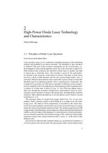
Figure 1 illustrates a typical PCM. system.
It consists
of a commutator to time-division multiplex each sampled information
channel, an encoder to convert the sampled input into a discrete
TRANSMITTING
DATA SOURCES
.__
SIGNAL C 0 N 0 IT I ON·
1-
EQUIPMENT
~
C 0 M U· "TAT 0 R
1-1
E N C 0 DE R
H
TRANS· M 1TT E R
I NG
COMMUNICATION
Ll NK
RECEIVING
'---to-IRE C E I V E R H
DEC 0 DE R
EQUIPMENT
~DECOMMU·
Fig. 1.--A typical PCM system
TATOR
OUTPUT Sl GNALS
.w
4
pattern of pulses representing the binary code including synchroni• zation, a transmitter, and a receiver to detect the information being transmitted over the communication link.
A decoder accepts
the received pulses from the receiver, separates clock and synchronization from the data, and regenerates the input sample.
The decommu-
tator reverses the function of the commutator so that coherent · information is presented ·at ·the output. CQmroutators used in time division multiplexing can be mechanical, electromechanical, or electronic.
The mechanical and electromechanical
devices are usually motor-driven rotating switches and are limited in operational speeds to a few hundred revolutions per second. These speeds are sufficient change very slowly.
fo~
channels in Which the signal variations
For more rapid signal variations, electronic
CQmmutators must· be used because only they are capable of the higher rates.
Electronic commutators usually consist of a number of gate
generators
~.Jhich
are interconnected in a manner such that the output
sates are enabled one at a time in a definite sequence. generator
(cl~ck)
A pulse
controls these devices.
The encoder changes the sampled input intelligence into a group of pulses Which represents the measured variable. to a small portion of the original signal.
Each pulse corresponds
The device which performs
this conversion is known as an analog-to-digital (A/D) converter and the output may be any one of several p·u lse code modulation waveforms.
Synchronization may be inserted into the pulse train by
special inputs from the commutator or may be added along with parity and other special information data in the encoder. is used to modulate the transmitter.
The encoder output
s · The transmitter is where the serial information is inserted onto the carrier.
Generally the transmitter generate·s either a
frequency modulated (FM) carrier or a phase modulated (PM) carrier.
The transmission requirements are rate) and threshold power.
ban~width (determin~d
by the bit
Ideally, two samples per cycle of the
input information is required, the actual number affecting bandwidth as does the number of binary bits per wrd.
Bandwidth heTe is the
product of the number of samples per cycle and the number of bits per data vxn;d.
The tl)Ore
l)i ts representing
the sample, the greater
the resolution, but the basic fr.equen-ey of the output 'signal increases resulting in a greater bandwidth for the transmitted signal. _ Th·r es.. hold power is the level necessary at the receiver to detect the presence of a pulse.
If the pulse power is too low compared to the
noise, ·even the best possible receiver will make mistakes.
Generally,
the threshold power necessary for acceptable operation requires a signal to noise ratio greater ·than 20 db. The
re~eiver ~erves to
detect the _information being transmitted.
The type of receiver is determined by the transmitted pulse.
The
receiver circuits should be designed so that maximum gain with minimum noise is provided. The decoder converts the digital data back to analog form. Synchronization and other extraneous information is processed as
.
intended by the design but does no original analog pulse.
.
influence the magnitude of the
The output of the decoder is a series of
quantized analog sampl,e s.
p ·Qvl Formats
PCM data is
~itten
in a format constructed of a series of
pulses called bits which wen gr.oupe.d form -words, frames, and subframes.
~~jPCM
we gene4ally have only two symbols to choose
The logic one (1) bit and the
from:
lo~ic
zero (0) bit.
Complete
information transfer is accompli$hed with these two symbols.
The
input signal is quantized into discrete voltage levels corresponding to the desired ~ina~y code. a signal into sixteen levels. series of one and zero bits. additional information;
Table 1 shows the result of quantizing Each level is represented by a Other bits may be added to represent
i.e., parity, synchronization, · etc.
bit series or syllables represent a PCM ~~rd. signal is
ampled a
~rd
These
Every time the input
is generated.
For a PCM system designed to sample several input variables a definite sequence must be established. commuta or generates a frame.
A complete cycle of the
The frame is composed of words and
must include additional synchronization to allow meaningful communication.
Figure 2 gives a typical P(}f format including bit repreo
sentation, syllables,
~rds,
and frames.
The generation of e format consisting of multiple frames is known as suboommutation and sampling of a particular variable more frequently than once within a frame is called super commutation. smchronization Synchronization mu$t b
acquired and maint ined if data is to
be successfully processed by the receiving equipment.
To insure this
7
TABLE 1
SIGNAL QUANTIZATION Level
Code
Voltage Range
15
1111
9. 37 5 < 10.000
14
111
s. 750
•
One
sh0
P u I s e (1 0 0 n s)
One
t
Shot
Dec a d e
Driver
Counter
cP
L a s e r Diode
Output
50ns Pulse Maximum
Fig. 4.--Encoder block diagram
.... -'='
2
Clock
4
3
5
7
b
8
3
2
10
9
Pulse
~1 p.s
~
-~
~500ns
- - - - - - - -. · ~
Dec ad e Counter
.1"--- -
ParaiiP.I Load/Sync PuIs e
Series
Data
r: ~l-c-100ns
c-: c-: c-i r-: I
I
I
I
[-i I
r-:
I
[-i
I
r-i ·r-: r-: [-: r-: r-i I
I
·
I
I
I
1
Convert Command
~,..._100ns
-~
Status (Mode Control
..,
1001(
6.4 p.s
Fig. 5.--Timing diagram
.... ""
-15v 15v
4T
v
U7
Rl
PARITY
R2
6 1 41 21 11 13
~ u1
3
-15v,.__ SAMPLE HOLD
INPUT
~·----~c=I-,-
tll5V MODE ·CONTROL
A/ D
cP,.._
ll~ ·oR . GATE
61
r ._~.
.?1_1
56
5v
2g