Paper ID #13230
3D-Printed Smart Lamp Workshop Dr. Nebojsa I Jaksic P.E., Colorado State University - Pueblo NEBOJSA I. JAKSIC earned the Dipl. Ing. degree in electrical engineering from Belgrade University (1984), the M.S. in electrical engineering (1988), the M.S. in industrial engineering (1992), and the Ph.D. in industrial engineering from the Ohio State University (2000). He is currently a Professor at Colorado State University-Pueblo teaching robotics and automation courses. Dr. Jaksic has over 60 publications and holds two patents. Dr. Jaksic’s interests include robotics, automation, and nanotechnology engineering education and research. He is a licensed PE and a member of ASEE, IEEE, and SME. Mr. Pratik Dilip Desai Ryan Van Deest Dr. Jude L. DePalma, Colorado State University, Pueblo
c
American Society for Engineering Education, 2015
3D-Printed Smart Lamp Workshop Abstract This work describes a student-driven workshop centered on designing and building smart lamps using inexpensive Makerbot Replicator 2 3D printers and Cypress Semiconductor’s CY8CKIT-42xx PSoC 4 Prototyping Kits. The main objective of the workshop, to improve the engineering students’ design skills and attitudes towards independent designs via exposures to modern technologies like 3D printing and PSoC (Programmable System-on-Chip) programming, was achieved. The following workshop students’ outcomes: (1) an ability to successfully design and 3D-print an object that is a part of an assembly; (2) an ability to successfully wire/solder LEDs and sensors to a PSoC, and (3) an ability to successfully program a PSoC as demonstrated by creating a smart lamp were also met as substantiated by pre- and post-tests, attitude questionnaires, and informal short interviews with participating students.
Introduction Computer and 3D-printing revolutions are in full swing. As a result, the need for engineers educated in both of these technologies is increasing. The mechatronics program at our institution has experienced a steady growth trying to meet this need. However, the curricular changes that follow these fast-paced technologies are often difficult to implement in the classroom in a timely manner. Often, new products become available but without appropriate documentation for quick implementation in educational laboratories. It may take a year or longer to develop a set of laboratory exercises for a new microcontroller or a 3D printer. Thus, the knowledge must come from other informal sources, like workshops, technical presentations, conferences, etc. Students are taught to embrace change and keep current. This is in accordance with ABET EAC General Criterion 3, Student Outcomes1 (i) “a recognition of the need for, and an ability to engage in life-long learning” and (k) “an ability to use the techniques, skills, and modern engineering tools necessary for engineering practice.” Benefits of hands-on design-based workshops where students actively learn by experimenting in informal educational settings are well-recognized in engineering education. Kolb’s experiential learning cycle theory2,3 supports experimentation. All engineering programs teach, promote, and value engineering design. The literature on design topics in engineering education is vast. In further sections, after the workshop description, an assessment of student learning and attitudes due to the implementation of 3D printers and PSoCs (Programmable System-on-Chip) is addressed. Completed student 3D-printed smart lamps are analyzed and a conclusion on the acceptance of these technologies by undergraduate students is derived. Successful smart lamps are used as an indication of student skills abilities. Student pre- and post-workshop questionnaires are developed, administered, and analyzed. Informal student interviews are conducted to confirm their attitudes towards these novel technologies.
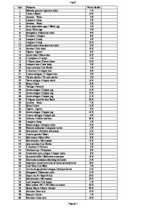
Smart Lamp Project Project Description Smart lamp is a USB programmable, USB powered LED-based 3D printed lamp that can exhibit a number of programmed behaviors (like change light colors) in response to proximity of objects around it. The smart lamp consists of a lamp base and a lamp shade. The lamp base hosts a Cypress PSoC 4 kit4 with three capacitive sensors for user interaction. The base cover hosts a NeoPixel ring consisting of 12 RGB LEDs with integrated programmable drivers. These LEDs are electrically connected to the PSoC. Also, the base cover is designed to accommodate many different student-built lamp shades. PSoC Creator 3.15,6 is used to program the smart lamp. Materials and devices required for successful completion of the smart lamp project are provided in the bill of materials, Table 1. Table 1. Bill of Materials for the Smart Lamp Workshop Part #
Part Name
Description Microcontroller board. http://www.cypress.com/?rID=92146
CY8CKIT-049-42xx
PSoC® 4200 Prototyping Kit
1643
NeoPixel Ring - 12 x WS2812 5050 RGB LED with Integrated Drivers Break-away 0.1" 36-pin strip male header (10 pieces)
LED light module. http://www.adafruit.com/product/1643 Male pin headers for assembly pusposes.
0.1" 36-pin Strip Right-Angle Female/Socket Header (5 pack)
Female socket headers for assembly pusposes.
392
1542
1127
734
UMPLA05NAT175S
N82E16812816056
Copper Foil Tape wth Conductive Copper foil used for making capacitive sensors. Adhesive - 25mm x 15 meter roll
Solder Spool - 1/4 lb SAC305 RoHS Solder Wire. RoHS Lead free. lead-free / 0.031" rosin-core - 0.25 lb / 100 g PLA plastic used for making the lamp parts. https://ultimachine.com/content/pla-175mmnatural-5lb-spool Nippon Labs Black 6 ft. USB cable USB cable for power and programming interface. A/Male to A/Female extension http://www.newegg.com/Product/Product.aspx? USB 6ft cable Model USB-6-MF- Item=N82E16812816056 BK 6 feet
Supplier
Qty
Units
Cypress Semiconductor
20
1
AdaFruit
20
1
AdaFruit
2
360
AdaFruit
2
180
AdaFruit
1
1
AdaFruit
1
1
2
1
20
1
PLA 1.75mm Natural 5lb on Spool
Unit Cost
Cost
$
4.00
$
80.00
$
6.75
$
135.00
$
4.95
$
9.90
$
4.95
$
9.90
$
19.95
$
19.95
$
24.95
$
24.95
$
101.00
$
202.00
$
3.99
$
79.80
$ Total
68
$
561.50
Workshop Description The workshop involved 11 students (two seniors and nine juniors) and ran on two Fridays, the first Friday for six hours and the second Friday for two hours. Students, the workshop developers, decided to limit student participation to juniors and seniors only due to the difficulty of the material and student maturity. During the first portion of the workshop, the student presenter (a senior and a 3D-printing lab technician) and a graduate student described 3D printing methods, discussed materials, taught students how to use the free software (Google SketchUp) to create their lamp designs, helped students create STL files, mentored students in using slicing software, and imparted their experiences with the engineering lab 3D printers. During the time between the two sessions students printed their designs. The second part of the
workshop dealt with the Cypress PSoC. Student presenters taught workshop attendees how to choose an appropriate device for the design, how to wire/solder capacitive sensors (CapSense7) and LEDs to the PSoC, how to assemble the smart lamps that they have printed previously, how to use PSoC Creator 3.0, and how to program the PSoC. At the end of the workshop all attendees created smart lamps of their own designs including the individually programmed color patterns and lamp behaviors. 3D Printing Design Portion In this part of the workshop students are introduced to the process of 3D printing including CAD (computer-aided design) programming for 3D printing, slicing 3D-printer software, 3D printing, removing parts from the printer, and cleaning the printed parts. All workshop participants printed the lampshades they designed and were successful in incorporating them with the provided lamp bases. Figure 1 depicts solid models of the lamp base and its cover. It also shows one of the bases designed and built for the workshop participants using lab 3D printers. It was calculated that students would not have time to print lamp bases as well as lamp shades in a single workshop.
Figure 1. 3D-printed lamp base designed by student presenters PSoC Design Portion PSoC (Programmable System-on-Chip) is a family of Cypress Semiconductors products. PSoC is an integrated circuit consisting of a CPU and mixed-signal arrays of configurable peripherals, both analog and digital. PSoC 4 includes a 32-bit ARM Cortex-M0 processor
running at 48MHz, with up to 36 I/Os, one 12-bit SAR ADC at 1 Msps, and two 8-bit DACs. PSoC 4 is programmed via PSoC Creator, the second generation software IDE (Integrated Design Environment). A screenshot of the PSoC Creator starting window is illustrated in Figure 2. Capacitive sensors are pieces of metal tape directly connected to the PSoC via wires. RGB LED rings consist of 12 LEDs that can be programmed.
Figure 2. Screenshot of the PSoC Creator starting window First, a ‘Hello World’ type project was created and programmed by students for verification of tool chain. Students created a simple circuit utilizing the on-board push button and LED, creating a push button to make circuit lighting the LED every time the push button was pressed. This project also demonstrated some key features of the IDE and the PSoC 4 such as the universal digital block (UDB), the schematic design entry of the IDE, and automated code generation for fixed-function and programmable components/peripherals. The PSoC IDE requires the user place components such as a digital input pin on the top level design panel, as shown in Figure 3. All pins (I/Os), used in the project should be components used from the components library. Once the component is placed on the top level design panel, and the project compiled, relevant component application programming interface (APIs) are generated that can be used to interact with that component. The user then has to assign the relevant PSoC 4 microcontroller pin to the pin components. This is done on the main project pins configuration panel, as shown in Figure 4. This is an important concept to grasp as students are more accustomed to the standard Cprogramming techniques. The PSoC Creator adds an additional step prior to the C-programming style that is the component library.
Figure 3. PSoC 4 Component Catalog
Figure 4. PSoC 4 pins configuration panel
The PSoC universal digital blocks (UDBs) allow users to configure their device with the features that are required for their particular projects. This is the key difference between the plethora of microcontrollers and a PSoC device. For example, a project may require ten pulse width modulation (PWM) output signals implemented via microcontroller peripherals. This cannot be achieved on an Arduino Uno. However, on the PSoC 4 device used on the development board, this can be easily achieved via configuring the UDBs as PWM blocks. The PSoC 4 has 4 dedicated timer/PWM peripheral blocks, where each can be configured to output two PWM signals. In addition the four UDBs can be configured to do the same, thus producing 16 PWM signals. On the successful completion of the ‘Hello World’ project, students used the PWM component from the components catalog to create a simple circuit that sends a 1Hz digital signal to the onboard LED. This demonstrated the above mentioned UDB functionality of the PSoC, along with the ease of use of the IDE for the implementation and configuration of more complex components. An important feature of the IDE is the ease of use of the datasheets for each component. The datasheets provide important information about the components configurations and APIs. The component datasheets were used extensively throughout the development stage of the lamp firmware. The students were then asked to build the lamp itself, with each stage of the build verified by students and the student instructors. The lamp firmware was programmed into the PSoC and the functionality verified by students. Figure 5 shows the top level design panel of the lamp firmware detailing the components used.
Figure 5. Smart lamp top level design panel Figure 6 shows students working on their capacitive sensors used to change colors of the RGB LED rings in their smart lamps. Figures 7 and 8 depict students testing their designs.
Figure 6. Student participants making their capacitive sensors
Figure 7. Student testing lamp base
Figure 8. Student testing capacitive sensor
Project Results All student participants finished their designs. Figure 9 shows some of the design solutions. This confirms that skill-based learning outcomes are achieved. At the end of the workshop, the project description and stl files were placed on thingiverse9.
Figure 9. Smart lamps created by workshop participants Student Objectives and Outcomes Assessment The main objective of the workshop is to improve the engineering students’ design skills and attitudes towards independent designs. It is accompanied with the following learning outcomes: (1) an ability to successfully design and 3D-print an object that is a part of an assembly; (2) an ability to successfully wire/solder LEDs and sensors to a PSoC; and (3) an ability to successfully program a PSoC. Pre-test and post-test are the knowledge-based tests and they show the knowledge gained due to the workshop. Results are provided in the graphs below. Figure 10 shows the test scores for 3D printing portion of the workshop while Figure 11 shows the test scores for the PSoC 4 portion of the workshop. The test questions are graded from 1 to 5, where 1 means the student answered the question incorrectly or didn’t answer the question at all, 2 means that the student demonstrated minor knowledge, 3 means that there is some major component missing in the answer, 4 means that some details are missing, and 5 means that the answer is complete. 3D-printing questions are adopted from Jaksic8. Only the second question is removed. Here the questions are repeated for completeness.
1. Discuss the two basic rapid prototyping classifications. 2. In the past few years a number of inexpensive additive manufacturing devices were introduced. Why? Why are they so successful?
3. Name as many materials as you can that are used in additive manufacturing. 4. An assembly of five parts is needed. What material (ABS or PLA) would you choose and why to 3D print the parts? 5. When a part fails to print or fails to print properly what may be the cause(s)?
PSoC 4 questions are the following. 1.
What does the abbreviation PSoC stand for?
2.
What processor architecture does the PSoC 4 use and what number of bits is it?
3.
To blink an LED on an output pin, what two ways can an output pin be configured on a PSoC 4?
4.
Describe the differences between an Arduino Uno and PSoC 4?
5.
Why would you use an Arduino Uno instead of a PSoC 4?
6.
Why would you use a PSoC 4 instead of an Arduino Uno?
5.00 4.00 3.00
Pre-test
2.00
Post-test
1.00 0.00 Q1
Q2
Q3
Q4
Q5
Figure 10. 3D-printing pre-test and post-test scores 5.00 4.00 3.00
Pre-test
2.00
Post-test
1.00 0.00 Q1
Q2
Q3
Q4
Q5
Q6
Figure 11. PSoC 4 pre-test and post-test scores
Attitude questionnaire consists of six statements rated on the five point Likert scale where 1 is the lowest and 5 is the highest rate and two open-ended questions (questions 7 and 8). Questions and results (average and standard deviation) are presented in Table 2. Table 2. The workshop attitude questionnaire No.
Statement
Average
σ
1
I found the 3D printing part of the workshop interesting.
4.89
0.33
2
I found the 3D printing part of the workshop useful.
5.0
0
3
I found the PSoC part of the workshop interesting.
4.78
0.44
4
I found the PSoC part of the workshop useful.
4.67
0.50
5
I found the soldering part of the workshop interesting.
4.43
0.79
6
I found the soldering part of the workshop useful.
4.71
0.76
Questions 7 and 8 were: “What is the most useful thing you learned at the workshop?” and “What improvement(s) would you suggest?” Students found the workings and the programming of a PSoC most interesting. However, they expressed a desire to spend more time in the workshop. During informal interviews students showed an increasingly positive attitude towards 3D printing and PSoCs. Since the PSoC technology was new for them they enjoyed it more. Also, being able to take home student-designed smart lamps was a great incentive. Judging by test scores, design project success, the attitude questionnaire, and informal interviews the main objective and the learning outcomes were strongly met. Several lessons were learned in implementing the workshop. While valuable in giving students access to new technologies, finding and/or motivating a student to organize such a workshop is difficult. The workshop seemed easy to implement at first, but we learned that a lot of work was involved and a lot of time. Not many student leaders are willing to spend that amount of time, especially with the heavy course work that most engineering programs have. Using the PSOC which combines a microcontroller (programming) and a PLA (digital design) into one system design may be a difficult concept for students to learn and grasp, especially third year students who may not have had classes in both of these areas. Finally the workshop was held on one day. By the end of the day, many of the students were tired and burned out. It would have been better if the workshop were held over two days. Summary This work describes a novel workshop that combines a 3D printing design with a PSoC design into a new student-developed product, a smart lamp. The projects’ main objective, to improve the engineering students’ designing skills and attitudes towards independent designs, was achieved. Also, the following learning outcomes: an ability to successfully design and 3D-print an object that is a part of an assembly; an ability to successfully wire/solder LEDs and sensors to a PSoC; and an ability to successfully program a PSoC were accomplished.
Bibliography 1.
2. 3. 4. 5. 6. 7. 8. 9.
Anon., Criteria for Accrediting Engineering Programs Effective for Reviews During the 2015-2016 Accreditation Cycle, ABET Engineering Accreditation Commission, 2015, Accessed on January 28, 2015. from http://www.abet.org/uploadedFiles/Accreditation/Accreditation_Step_by_Step/Accreditation_Documents/Curre nt/2015-2016/E001%2015-16%20EAC%20Criteria%2011-7-14.pdf Kolb, D. A., Experiential Learning: Experience as the Source of Learning and Development, Prentice Hall, Englewood Cliffs, N.J., 1984. Harb, J. N., Durrant, S. O., and Terry, R. E., ”Use of the Kolb Learning Cycle and the 4MAT System in Engineering Education,” Journal of Engineering Education, Vol. 82, April 1993, pp. 70-77. Anon., “PSoC 4 CY8CDIT-049-4xxx Prototyping Kits,” Cypress Semiconductors, http://www.cypress.com/?rid=92146 Anon., “PSoC Creator 3.1,” Cypress Semiconductors, http://www.cypress.com/psoccreator/ Hawse, A., “PSoC Creator 101 Lessons,” Cypress Semiconductor, https://www.youtube.com/watch?v=Kd7aigTZSg&index=2&list=PLIOkqhZiy83F-sOQhHyX8dJjebkWqZA3Y Anon., “PSoC 4 CapSense Design Guide,” Cypress Semiconductor, http://www.cypress.com/?rID=78578 Jaksic, N., “Novel Experiential Learning Practices in Engineering Education Based on Inexpensive 3D Printers,” Computers in Education Journal, Vol. 5, No. 4, pp. 2-17, October-December 2014. Desai, P. and VanDeest, R., “IEEE Lamp Work Shop,” accessed on April 19, 2015 at http://www.thingiverse.com/thing:654964