24 Volt LVC (Low Voltage Gontrol)
M A G N E T I CM O T O R C O N T R O LS Y S T E M S I N T R OUDC T I O N T h e s i n g l e a n d t h r e e p h a s e D e l t a d e fi n i t e p u r p o s eL o w V o l t a g e C o n t r o l ( L V C ) m o t o r s t a r t e r s h a v e b e e n d e s i g n e d e x c l u s i v e l yf o r u s e o n D e l t a machinery.
;
T h e b a s i c f u n c t i o n o f a D e l t a d e f i n i t e p u r p o s es t a r t e r i s t o p r o v i d eO N O F F m o t o r c o n t r o l . I n a d d i t i o n t o p r o v i d i n gO N - O F Fc o n t r o l ,e v e r y D e l t a motor starter offers the followino features:
Motor OverloadProtection- All startersare supplied with thermaloverloadrelayswhich protectthe power heat retool motor from burnoutsdue to excessive s u l t i n gf r o m a s u s t a i n e dm o t o r o v e r l o a d e, x t e n d e d m o t o rc y c l i n go , r s t a l l e dr o t o r . No Voltage or Low VoltageProtection (LVP) - No voltageor low voltageprotectionpreventsthe dangerous restartingof a power tool following a temporary p o w e r f a i l u r e .U p o n a l o s so f v o l t a g eo r a r e d u c t i o n of voltage,the magneticcontactorin the starterwill open. When power is restored,the motor will not , u t m u s tb e m a n u a l l yr e s t a r t e d a u t o m a t i c a l lrye s t a r t b b y p u s h i n gt h e s t a r tb u t t o no f t h e O N - O F Fs w i t c h .
\-
Low Voltage Control (LVC) -The Delta definite p u r p o s em o t o rs t a r t e r sp r o v i d el o w v o l t a g ec o n t r o al s a u n i q u e s a f e t yf e a t u r e .T h e p u s h b u t t o nO N - O F F s w i t c ho p e r a t e sa t a 2 4 v o l t l e v e l ,n o t a t l i n ev o l t a g e . f h e 2 4 v o l t l o w v o l t a g e c o n t r o l e l i m i n a t e st h e p o s s i b i l i t yo f d a n g e r o u se l e c t r i c a ls h o c k t o t h e operator. T h i s m a n u a li n c l u d e sa d e s c r i p t i o no f t h e b a s i cL V C m o t o r s t a r t e r s , instructionsfor wiring the startersto the powersource,and instructions for changingthe voltageof an LVC motor starter.
D a t e d5 - 1 0 - 8 5
P a r t N o . 4 3 8 - 01 - 6 5 5 - 0 0 0 2 o Delta lnternalonal
Machinerv
Coro. 1985
TABTE OFCOIIITETTITS In t r o d u c t i o n . S a f e t yR u 1 e s . . . . . . . . . . . . c o t o rS t a r t e r . . . . . . . . . . S i n g l eP h a s eL V C M a g n e t i M InstructionsFor ConnectingThe SinglePhaseMotor Starter T o T h e P o w e rS u p p l y T h r e eP h a s eM a g n e t i cM o t o rS t a r t e r InstructionsFor ConnectingThe Three PhaseMotor Starter T o T h e P o w e rS u p p l y C h a n g i n gV o l t a g eO f L V C M o t o r S t a r t e r s . . . . . . . . . . . . . . . . . . M o u n t i n gT h e L V C M o t o rS t a r t e rT o A S t e e lS t a n d . . . . . . . . . . .
' . . . . . . . . ' . . . . .1 .... .,.".'.'2 ............................3 ...........'.'...'......5 ..........................6 ........................8 .....................9 . . . . . . . . . .11
RUTES SAFETY Installingand servicingshould alwaysbe accomplished 1. by qualifiedelectricalpersonnel. Readthe instructionmanualbeforewiring and operating 2. this motor starter. Failure to follow instructions can cause injury. 3. Always disconnectthe electricalpower before removing the coverof the starter. 4. Operate the motor starter only with the cover of the starterin place. Do not operatethe machineunlessthe motor starter is 5. properly groundedas specifiedin the instructions. Follow nationaland local electricalcodeswhen wiring 6. the motor starter. 7. Always use proper heater coils as specified in the heater coil chart locatedon the insideof the startercover. 8. Make sure the motor starter is disconnectedfrom the electrical power source before the primary connections of the control transformerare changed. 9. The LVC Motor Starter has been designed and engineeredfor useonly on Delta Machinery. 10. Occasionally inspect the starter to ensure that it is securelymounted,cleanand dry. 11. Always use the LVC Motor Starter with an electrical disconnectswitch with over-currentprotection.
STARTER MOTOB LVCMAGNETIC PHASE SINGTE Fig. 1, illustrates the standard single phase LVC magnetic motor starter, Delta Part No. 52-704.
'\-
T h e s t a r t e ri s m a d eu p o f f o u r b a s i cc o m p o n e n t s :1 ) o v e r l o a d block, 2) magneticcontactor,.3)transformer,and 4) start/stop s t a t i o n .T h e s t a r t / s t o ps t a t i o ni s n o t s h o w ni n F i g . 1 . N e i t h e r a r e t h e i n p u t c o n n e c t i o n fsr o m t h e s t a r t / s t o ps t a t i o n ,i n p u t c o n n e c t i o nfso r s i n g l ep h a s ee l e c t r i c apl o w e r ,o r t h e l e a d sf r o m the motor. c i a g r a mo f t h e s i n g l ep h a s e A w i r i n g d i a g r a ma n d s c h e m a t i d L V C m a g n e t i cm o t o r s t a r t e ri s s h o w ni n F i g .2 . T h e w i r i n g d i a g r a mi n d i c a t e tsh e r e l a t i v ep h y s i c al o c a t i o no f e a c h c o m p o n e n tw , i r e , a n d t e r m i n a l ;w h e r e a st.h e s c h e m a t i c of the comd i a g r a md o e s n o t s h o w t h e p h y s i c arl e l a t i o n s h i p p o n e n t s .T h e s c h e m a t i d c i a g r a md o e ss h o w i n a s t r a i g h tl i n e f o r m t h e c i r c u i tf u n c t i o n so f t h e v a r i o u sc o m p o n e n t s .
INTERLOCKSWITCI-{ 577-OO-OO1-0262
T h e s i n g l e p h a s es t a r t e r i s c o m p r i s e d o f a p o w e r c i r c u i t a n d a control circuit.
The oower circuit carriesthe motor loadcurrentand is shown w i t h h e a v yl i n e si n t h e w i r i n ga n d s c h e m a t idci a g r a mtso r e p r e s e n th e a v yg a g ew i r e s i z e df o r t h e m o t o r c u r r e n t .I n t h e m o t o r s t a r t e rt,h e p o w e rc i r c u i ti s w i r e dw i t h b l a c kw i r e s .
T h e m a i n f u n c t i o n o f t h e c o n t r o lc i r c u i t i s t o s t a r t a n d s t o p the electric motor by meansof the start/stoppushbuttons. T h e d i a g r a m isn F i g . 2 i l l u s t r a t etsh e c o n t r o lc i r c u i tw i t h l i g h t . he l i n e st o r e p r e s e nl ti g h tg a g ew i r e s i z e df o r c o n t r o lc u r r e n t T r ith fuse, c o n t r o l c i r c u i t c o n s i s t so f t h e c o n t r o lt r a n s f o r m ew start/stoppush buttons, start button interlockcontact,magn e t i c c o n t a c t o rc o i l , a n d o v e r l o a ds w i t c h .T h e c o n t r o lc i r c u i t i s w i r e dw i t h r e dw i r e si n t h e m o t o r s t a r t e r .
TRANSFORMER 438-O1-O19-OO12
MAGNETIC CONTACTOR 583-OO-OO1-0066
(-
OVERLOAD BLOCK 584-OO-OO1-OO38
FUSE
1-027-OOO8
GROUND STRIP \-
M O T O RT E R M I N A L S
S I N G L EP H A S E START,/STOP POWERINPUT STATION TERMINALS TERMINALS
F I G . 1 - S T A N D A R D S I N G L E P H A S EM O T O R S T A R T E R . D E L T AN O . 5 2 - 7 0 4
lCONNECT AS PERLINE VOLTAGE
START
sroP r l z -L---
I
3-
STATION START/STOP
,
tr\+
\-/
COIL MAGNETICCONTACTOR OL L i L 2 t 2 3
BLOCK OVERLOAD WITHHEATER
F8fi?E.m
S TART STATION
FUSE
WIRINGDIAGRAM
J
L r l.#
TRANSFORMER CONTROL
-
I
:
t
l J 5l rl
l r b l
-ii-
l
l
l
tt '*-i
2 r r 3
MAGNETIC@NTACTOR OL
CLOSED NORMALLY SWITCH OVERLOAD S C H E M A T I CD I A G R A M
LEGEND
F I G . 2 - W I R I N G D I A G R A M A N D S C H E M A T I CD I A G R A M O F T H E S I N G L E J P H A S E L V C M O T O R S T A R T E R ,D E L T A N O . 5 2 - 7 0 4
INSTRU CTIONS FOBCONNECTING THESINGTEPHASEMOTOBSTARTER T OT H EP O W ES BU P P L Y I n g e n e r a ls, t a t i o n a r yt o o l s o r d e r e dw i t h a s i n g l ep h a s em o t o r 1 - 1 / 2 h o r s e p o w eorr l e s sa r e s h i p p e df r o m t h e f a c t o r yw i t h a c o r ds e ta n d p l u g .N o f i e l dw i r i n gi s n e c e s s a r y . S t a t i o n a r yt o o l s o r d e r e dw i t h a s i n g l ep h a s em o t o r g r e a t e r t h a n 1 - 1 1 2h o r s e p o w em r u s t b e w i r e d i n t h e f i e l d .T h e s i n g l e p h a s eL V C m o t o r s t a r t e rs h o u l db e w i r e da sf o l l o w s : B r i n g t h e i n p u t p o w e rc o r d t h r o u g ht h e e n t r a n c eh o l e i n t h e bottom of the starterenclosure,Fig. 3. Connectthe black p o w e r l e a d t o t e r m i n a lL 1 , t h e w h i t e p o w e r l e a dt o t e r m i n a l L2, and the greengroundleadto the groundstrip in the lower left handcornerof the starterenclosure.
\-
Fis.3
Severalpoints must be stressedand closely followed when connectingthe input powerto the motor starter. 1. To preservethe dust-tight integrity of the motor starter, an oil-tight box connector should be usedfor fastening the input cableto the starterenclosureat the entrancehole. 2. lf copperstrandedwiresare usedfor the input leads,the wires must be soldereddipped or tinned beforethey are conn e c t e dt o t e r m i n a l sL 1 a n d L 2 a n dt h e g r o u n ds t r i p .
S C R E W SO N T O P O F T H E T E R M I N A L B L O C KA R E U S E DT O C L A M PT H E W I R E SI N T H E B L O C K
3. The wires must be connectedto terminalsL1 and L2 t h r o u g ht h e f r o n t f a c eo f t h e t e r m i n a lb l o c k a s s h o w ni n F i g . 4 . T h e s c r e w so n t h e t o p o f t h e t e r m i n a b l l o c ka r eu s e df o r c l a m p i n g t h e w i r e si n t h e t e r m i n a b l lock. 4. T h e g r o u n d s t r i p h a sp r o v i s i o nfso r f o u r g r o u n dl e a d s . The input power, start/stop station, and motor must be grounded via the ground strip. Two ground wires must neverbe insertedin the groundstrip underone screw. TERMINALSL1 - L2 CONNECTIONS 5. l f m e t a l c o n d u i t i s u s e d i n p l a c e o f c a b l e ,t h e g r e e n ground wire from the single phase input power system is omitted.
Fis. 4
THREEPHASEtVC MAGiIETICMOTORSTARTER F i g . 5 , i l l u s t r a t e st h e s t a n d a r dt h r e e p h a s e L V C m a g n e t i c motor starter,Delta Part No. 52-702.
T h e w i r i n g d i a g r a mi n d i c a t e tsh e r e l a t i v ep h y s i c al o c a t i o no f e a c hc o m p o n e n tw , i r e , a n d t e r m i n a l ;w h e r e a st,h e s c h e m a t i c d i a g r a md o e s n o t s h o w t h e p h y s i c arl e l a t i o n s h iopf t h e c o m p o n e n t s .T h e s c h e m a t i cd i a g r a md o e s s h o w i n s t r a i g h tl i n e f o r m t h e c i r c u i tf u n c t i o n so f t h e v a r i o u sc o m p o n e n t s .
The three phasestarter consistsof four basiccomponents: (1) overload block with heaters,(2) magneticcontactor (3) transformer,(41 start/stopstation. The start/stopstation The three phaseLVC motor starter is comprisedof a power i s n o t s h o w n i n F i g . 5 . N e i t h e ra r e t h e i n p u t c o n n e c t i o n s c i r c u i ta n d a c o n t r o lc i r c u i t .T h e d i a g r a m si n F i g . 6 i l l u s t r a t e s the power circuit with heavy lines to representheavy gage from the startTstop stationand the input connections from the w i r e s i z e df o r t h e m o t o r c u r r e n t ;w h e r e a st,h e c o n t r o lc i r c u i t threephasemotor or powersupply. i s s h o w nw i t r i i i g h t l l n e si n t h e d i a g r a mtso r e p r e s e nl it g h tg a g e wire sizedfor control current.In the motor starter.the power A wiring diagramand schematicdiagramof the three phase c i r c u i t i s w i r e d w i t h b l a c k w i r e s a n d t h e c o n t r o l c i r c u i t i s w i r e dw i t h r e dw i r e s . LVC magneticmotor starteris shownin Fig. 6.
I N T E R L O C KS W I T C H 577-OO-OO1-0262
TRANSFORMER 438-01-O19-OO30
MAGNETIC CONTACTOR 583-OO-OO1-OO66
OVERLOAD BLOCK 584-OO-OO2-OO38
43
FUSE 1-027-0008
GROUND STRIP
START/STOP T H R E EP H A S EP O W E R MOTOR I N P U TT E R M I N A L S TERMINALS S T A T I O NT E R M I N A L S
F I G .5 -
S T A N D A R D T H R E EP H A S E M O T O R S T A R T E R ,
DELTANO. 52.702
START I
I
i
t-r
l-l
I
STOP l +t
l l
l
^ H
a-
3 START/STOPSTATION
_.qrz --1rfu OVERLOAD BLOCK WITHHEATERS LfL2L3 _+++r
|
2
| 3-_-J
IIT:F [- ,=,___o-J ioffEh.o.nlg5o. ,?I+il-
MAGNETICCONTACTOR COIL
FUSE
W I R I N GD I A G R A M
CONTROL TRANSFORMER I-t^
| | ^
L c r i L g r r 2 r l 3
@NTACTOR MAGNETIC
D IAGRAM S C H E MA T IC
CLOSED NORMALLY SWITCH OVERLOAD
LEGEND F I G . 6 - W I R I N G D I A G R A M A N D S C H E M A T I CD I A G R A M O F T H E T H R E E P H A S E L V C M O T O R S T A R T E R .D E L T A N O . 5 2 . 7 0 2
THETHBEEPHASEMOTORSTABTEB FORCOTIIIIECTITTIG IIIISTRUCTIOIIIS SUPPTY TOTHEPOWER All threephasemotor startersmust be wired in the f ield. Refer ts Fig. 7, bring the three phasepower cord through the entrancehole in the bottom of the starterenclosure.Connect the red, white and black power leadsto terminalsL1-L2-L3 and the greenground leadtq the groundstrip in the lower left handcornerof the starterenclosure. N O T E : l f t h e m a c h i n er u n s b a c k w a r d so n c e t h e m o t o r i s en y t w o o f . t h e t h r e e i n p u t t u r n e d o n , s i m p l y i n t e r c h a n ga p o w e r l e a d si n t e r m i n a l sL l - L 2 - L 3 .
Fis.7
Severalpoints must be stressedand closely followed when connectingthe input powerto the motor starter. 1. To preservethe dust-tightintegrityof the motor starter, an oil-tight box connectorshould be usedfor fasteningthe input cableto the starterenclosureat the entrancehole. 2. lf copperstrandedwiresare usedfor the input leads,the wires must be soldereddipped or tinned before they are conn e c t e dt o t e r m i n a l sL l - L 2 - L 3 a n d t h e g r o u n ds t r i p .
O N T O PO F T H E T E R M I N A LB L O C KA R E SCREWS U S E DT O C L A M PT H E W I R E SI N T H E B L O C K
The wires must be connectedto terminals Ll -L2-L3 3. t h r o u g ht h e f r o n t f a c eo f t h e t e r m i n a lb l o c k a s s h o w ni n F i g . 8 . The scr'ews on.the top of the terminalblock are usedfor clamping t h e w i r e si n t h e t e r m i n a b l lock. 4. The ground strip has provisionsfor four ground leads. The input power, start/stop station, and motor must be g r o u n d e dv i a t h e g r o u n ds t r i p .T w o g r o u n dw i r e sm u s t n e v e r be insertedin the groundstrip underone screw. 5. l f m e t a l c o n d u i t i s u s e d i n p l a c eo f c a b l e ,t h e g r e e n groundwire from the three phaseinput powersystemis omittted.
TERMINALS L1 - L2 - L3 CONNECTIONS Fig.I
J
CHAIIIGIITIG VOTTAGE OF tVC MOTORSTARTERS ,o
5
o o (!
,*
A-
s o
ttt
(v
o a o v
f*
o o (o It
lf it ever becomesnecessaryto operate a stationary power tool f r o m a l i n e v o l t a g eo t h e r t h a n t h e v o l t a g e f o r w h i c h t h e t o o l w a s o r i g i n a l l y w i r e d , t h r e e s t e p sm u s t b e f o l l o w e d t o m o d i f y t h e e l e c t r i c a lp a c k a g ef o r o p e r a t i o nf r o m t h e n e w l i n e v o l t a g e . Disconnect Motor Starter from power source and proceed as
?;Tiffi--
11 5 V O L TT A P
S T E P1 - R e m o v e t h e m o t o r j u n c t i o n b o x c o v e ra n d c h a n g e t h e m o t o r l e a d c o n n e c t i o n sf o r t h e p r o p e r l i n e v o l t a g ea s s h o w no n t h e m o t o r n a m e p l a t e . Step 2-Changethe primary of the control transformer.Move the transformer primary pigtail to the proper terminal c o r r e s p o n d i nt o g t h e n e w i n p u tv o l t a g e .S e eF i g . 1 0 . NOTE: For 2O8volt powersysrems, connectthe transformer to the 200 volt tap, NOT the 230 volt tap. Continued on next page
F I G . 1 O _ C H A N G I N GV O L T A G E
COMMON
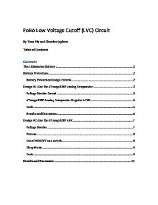
STEP 3-Change the heaterelementsin the overloadblock for rating shown on the motor the proper voltage/amperage nameplate, For every LVC motor starter,a heatercoil chart is locatedon the inside cover of the LVC motor starter enclosure' See F i s .1 1 . Note from the motor nameplate,the full load current for the n e w l i n e v o l t a g e . M u l t i p l y t h e f u l l l o a dc u r r e n tb y 0 . 9 , a n d select the heatersfrom the chart equal to or immediately greaterthan the product of 0.9 times the full load amperes. to specifyheatersfor a For example: Assumeit is necessary HP,230 volt motor with a nameplatefull load three phase,71/2 ampereratingof 22 2 2 x O . 9 = 1 9 . 8a m p e r e s Specify HEATER NO. CR123C2288 lrom chart. Three (3) heatersrequiredfor threephasepower.
P/N CR123c --
,3iil .37 .41 .46 .52 .57 .61 .67 .75
.u
.94 1.03 1.14 1.30 1.42 '!.61 1.72 1.93 2.10 2.9 2.U 2.86 3.13 3.32 368 4.08 4.61 5.21 5.62 6.12 6.8i1 7.70 8.€ 9.r9 9.92 11.1 12.2 13.5 14.6 1 6 .r 17.9 19.3 20.5 22.6 24.8 27.O
co36A co39A c0434 c0484 c054A c060A c0664 c0714 @78A c087A c0074 c109A c118A c131A c148A cr53A c184A cl96A c220A c239A c268A c3014 c3264 c3564 c3794 c419A Crt66A c5264 c5924 c630A c695A crTaA c867A c95sA c1048 c 11 3 8 c1258 c1378 c1518 cl638 c1808 c1988 c214tJ c2288
czsoB c2738
P/N CR123c
3 3 J
3 3 3 3 3 3 3 3 3 3 3 3 6 6 6 6 6 10 l0 10 to 10 15 15
.39 c054A .42 c0604 .45 c066A .51 c0714 .56 c0784 .65 cmTA .73 c097A .81 c109A .90 c118A 1.00 c131A 1.10 c148A ' 1. 2 1 c1634 1.35 c18{A 1.50 cl95A 1.64 c2204 c239A 1.78 1.98 c268A c3014 215 c326A 2.42 c3s6A | 2.88 c379A | 3.22 3.53 -c419A | c466A | 389 4.30 c5264 l 4.77 c592A I c530A I 5.14 c695A I 5.63 c778A | 6.26 7.15 c867A I 7.58 c955A | c1048 I 8.39 9 . 1 1 I C1138 I c1258 | 967 I 1.0 cr37B i c1518 | 11 . 9 14,3 c1638 | c1808 | 16 . 1 ct98B | 17.2 19.2 c2148 | c2288 | 20.5 c2508 | 21.8 c2738 I 23.4 c3038 I 26.1 CgtoB | 27.O
n n n
25 25 30 30 30 35 Q
45 50 50 60 60
m
70 t0 $
3 3 3 3 3 3 3 3 3 3 3 3 3 6 6 6 6 F
6
10 12 12 15
15 15 n N
25 25 30 30 35
35 40 45
50 60
60 70
80 80 80 90 90
T H R E EP H A S E
S I N G L EP H A S E Fig.11
10
\
ilOUiITIiIG THEtVC II'IOTOR STABTEB TOA STEET STAIIID ilhen field mounting an LVC motor starter, it is necessary ( to vprovide three 5/16" mounting holes and a 2" x 6,, cable clearanceslot in the baseor cabinet of the machine. SeeFig. 12. The LVC enclosureis suppliedwith three 1/4"-20 weld nuts tacked in the bottom of the enclosureat the position shown in Fis. 12.
-T I
.3t (5/16l 3 HOLESREOD.
7"
Assemblethe LVC Motor Starter flush to the baseor cabinet of the machine using three flat washersand three 1/4,'-20 machinescrewssupplied.
F I G . 1 2 - M O U N T I N G H O L E SA N D CABLE CLEARANCE SLOT FOR T H E L V C S T A R T E RE N C L O S U R E
11
''iq
^itrTEIJA PARTS,SERVICEOR WARRANTYASSISTANCE to aremanufactured dndaccessories All DeltaMachines network a of and are servicedby highqualitystandards stations service factoryservicecentersand authorized inforlistedin yourowner'smanual.To obtainadditional
yourDeltaqualityproductor to obtain mationregarding pleasecallDelta's parts,serviceor warrantyassistance, number. telephone toll-free'hotline'
Delta maintainsa modern, efficientParts Distribution Center,maintainingan inventoryof over 10,000Parts locatedin MemPhis, Tennessee.
M e m p h i s ,T N 3 8 1 1 8 4290 Raines Road Phone: (901) 363-8800
#e.TL'NE
Highlyqualifiedand experienced CustomerService are standing Representatives by to assist you on weekdaYs f r o m 8 : 0 0A . M . t o 5 : 0 0 P . M . M e m p h i st i m e .
800-223-PART 800-238-PART) (ln Tennessee
CENTERS FACTORYSERVICE ALABAMA 35209 Birmingham Corporation PorterCable Road,Suite105 131W.Oxmoor 205-942-6325 CALIFORNIA LosAngeles90007 CorPoration PorterCable 2400S. GrandAvenue 213-749.0386
0rlando32803 Corporalion PorteFCable 18071/2WinlerParkRoad 305-644-8100 Tampa33609 PorleiCableCorpolation Blvd. 4536W. Kennedy 813,877-9585
MASSACHUSETTS 02134 Boston(Allston) PoilerCableCorporalion Skeet 414Cambridge 617.782-1700
NEWYORK 11365 Flushing Corporation PorteFCable 175-25HoraceHardingExpwy 212-225-2040
TEXAS Dallas75220 Corporation PorletrCable Freeway 10714N. Spemmons 214-353-2996
MICHIGAN GrandRapids49506 Corporation PorteFCable DriveS.E. 2750Birchcresl 616-949-9040
NORTHCAROLINA 28209 Charlotte CorPoration PorlerCable 4612SouthBoulevard 704-525,4410
Holston77092 Corporation PorteFCable SuiteB-9 5201Nlitchelldale, 713-682-0334
(Detroit) 48075 Southiield Corporation PorlerCable W. Eight[4ileRoad 18650 313-569-4333
oHto 44146 Cleveland Corporation PorterCable Road 5188Richmond 216-675-1244
Orange92668 Corporalion PorterCable Blvd. 385NorthAnaheim 714-634-4111
GEORGIA ForestPark30050 CorPoration PorteLCable Road 4017Jonesboro 404363-8000
94577 SanLeandro Corporation PorteFCable Street 3039Teagarden P . OB . o x1 9 1 3 415-357-9762
tLLtN0ts (Chicago) 60101 Addison Corporation PorteFCable 311LauraDrlve 312-628-6100
MINNESOTA 55429 l\rinneapolis Corporation PorlerCable North 431568thAvenue 612-561-9080
COLORADO Denver80207 CorPolation PorterCable 4900E. 39thAvenue 303,388-5803
LOUISIANA Kenner70062 CorPoration PorterCable HwY Memorial 2440-0Veterans 504.469-7363
MtssouRl
CONNECTICUT 06040 Manchester Corporalion PorterCable Turnpike 57Tolland 203-646-1078
IIARYLAND 21205 Baltimore Corporation PorterCable Avenue 4714Erdman 301-483-3100
FLORIDA 33014 Hialeah Corporation PorteLCable 16373 NW57lhAvenue 305-624-2523
20781 Hyattsville Corporation PorlerCable Avenue 4811Kenllworth 301,779-8080
City64116 NorthKansas CorPoration PorterCable 1141SwiilAvenue P.0.Box12393 816-221-2070 63119 Si.Louis CorPoralion PorteFCable 7574WatsonRoad 314-968-8950 NEWJERSEY Union07083 on Corporat PorlerCable 945BallAvenue 201-964-1730
43215 Columbus CorPoration PorlerCable Avenue 4560Indianola 614-263-0929 PENNSYLVANIA 19020 Bensalem CorPoratlon PofterCable 95 Expressway lnduslrial Center Lanes 3599l\.4eadow 14 215-638-41 RHODEISLAND Provldenle 02914 Corporation PorlerCable Avenue 1009Waterman 401-434-3620
78218 SanAnlonio PorterCable CorPoralion 2600N.E.Loop410 512.654-1061 UTAH SaltLakeCity84115 CorPoralion PorterCable 2990S.W.Temple 801-487-4953 VIRGINIA 23220 Richmond CorPoralion PorterCable Road 1705Dabney 804-257"7348 WASHINGTON Renlon98055 PorteFCable Corporation 43rdSkeet 268Soulheasl 206,251-6680 wlscoNsrN 53222 Milwaukee CorPoration PorteLCable Street 10700 W. Burleigh 414.774.3650
P r i n t e di n U . S . A . N u p p P r i n t i n gC o .