OCEAN/ESS 410
Lecture/Lab Learning Goals • Know how sediments are characterized (size and shape) • Know the definitions of kinematic and dynamic viscosity, eddy viscosity, and specific gravity • Understand Stokes settling and its limitation in real sedimentary systems. • Understand the structure of bottom boundary layers and the equations that describe them • Be able to interpret observations of current velocity in the bottom boundary layer in terms of whether sediments move and if they move as bottom or suspended loads – LAB
15. Physics of Sediment Transport William Wilcock (based in part on lectures by Jeff Parsons)
1
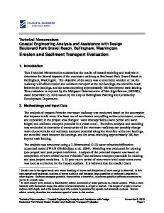
• There are number of ways to describe the size of sediment. One of the most popular is the Φ scale. φ = -log2(D) D = diameter in millimeters. • To get D from φ D = 2-φ
φ
Diameter, D
-6
64 mm
Cobbles
-5
32 mm
Coarse Gravel
-4
16 mm
Gravel
-3
8 mm
Gravel
-2
4 mm
Pea Gravel
-1
2 mm
Coarse Sand
Type of material
Sediment Characterization
0
1 mm
1
0.5 mm
Medium Sand
2
0.25 mm
Fine Sand
3
125 µm
Fine Sand
4
63 µm
Coarse Silt
5
32 µm
Coarse Silt
6
16 µm
Medium Silt
7
8 µm
Fine Silt
8
4 µm
Fine Silt
9
2 µm
Clay
Sediment grain smoothness
Coarse Sand
Sediment grain shape - spherical, elongated, or flattened Sediment sorting
% Finer
Sediment Characterization
2
3
4
Grain size
1
Sediment Transport Two important concepts • Gravitational forces - sediment settling out of suspension • Current-generated bottom shear stresses sediment transport in suspension (suspended load) or along the bottom (bedload)
Definitions
Shields stress - brings these concepts together empirically to tell us when and how sediment transport occurs 5
1. Dynamic and Kinematic Viscosity
2. Molecular and Eddy Viscosities Molecular kinematic viscosity: property of FLUID
The Dynamic Viscosity µ is a measure of how much a fluid resists shear. It has units of kg m-1 s-1 The Kinematic viscosity ν is defined
ν=
6
The molecular kinematic as the ‘kinematic viscosi the fluid and is the appro laminar. It quantifies the collision of molecules. (It viscous).
Eddy kinematic viscosity: property of FLOW
µ ρf
In flows in nature (ocean), eddy viscosity is MUCH MORE IMPORTANT!
where ρf is the density of the fluid. ν has units of m2 s-1, the units of a diffusion coefficient. It measures how quickly velocity perturbations diffuse through the fluid.
The Eddy Kinematic Visc and is the appropriate vis flow. It quantities the diffu “packets” of fluid that oc flow when the flow is turb
About 104 times more important
7
8
2
3. Submerged Specific Gravity, R R=
ρp
ρp − ρ f ρf
Sediment Settling
Typical values:
ρa
f
Quartz = Kaolinite = 1.6 Magnetite = 4.1 Coal, Flocs < 1
9
10
Settling Velocity: Stokes settling Settling velocity (ws) from the balance of two forces gravitational (Fg) and drag forces (Fd)
Fd ∝ ( Diameter ) × ( Settling Speed )
× ( Molecular Dynamic Viscosity )
(
× ( Acceleration of Gravity )
)
(
)
(
ws
(ρ =k
ws = k
∝ ρ p − ρ f Vg ∝ ρ p − ρ f D 3 g
∝ means "proportional 11to"
Balance of Forces
)
Dws µ = k ρ p − ρ f D 3 g
∝ Dws µ Fg ∝ ( Excess Density ) × ( Volume )
Settling Speed
Fd = Fg
ws =
(ρ
p
µ p
)
− ρ f D2 g
)
− ρf ρf
ρf
1 RgD 2 18 ν
µ
D2 g
Write balance using relationships on last slide k is a constant
Use definitions of specific gravity, R and kinematic viscosity ν k turns out to be 1/18
12
3
Limits of Stokes Settling Equation 1.
Assumes smooth, small, spherical particles - rough particles settle more slowly 2. Grain-grain interference - dense concentrations settle more slowly 3. Flocculation - joining of small particles (especially clays) as a result of chemical and/or biological processes - bigger diameter increases settling rate 4. Assumes laminar settling (ignores turbulence) 5. Settling velocity for larger particles determined empirically
Boundary Layers
13
14
Bottom Boundary Layers The layer (of thickness δ) in which velocities change from zero at the boundary to a velocity that is unaffected by the boundary
u
z
y
x
Outer region z ~ O(δ) Intermediate layer Inner region
15
δ
δ is likely the water depth for river flow. δ is a few tens of meters for currents at the seafloor
• Inner region is dominated by wall roughness and viscosity • Intermediate layer is both far from outer edge and wall (log layer) • Outer region is affected by the outer flow (or free surface)
16
4
Shear stress in a fluid
The inner region (viscous sublayer)
Shear stresses at the seabed lead to sediment transport z
y
• Only ~ 1-5 mm thick • In this layer the flow is laminar so the molecular kinematic viscosity must be used
x
force rate of change of momentum τ = shear stress = = area area
τ=µ
∂u ∂u = ρ fν ∂z ∂z
17
18
Shear velocity u* Sediment dynamicists define a quantity known as the characteristic shear velocity, u*
∂u ∂z ∂u τ = ρν e = ρu*2 = Constant ∂z
• Generally from about 1-5 mm to 0.1δ (a few meters) above bed • Dominated by turbulent eddies • Can be represented by:
u*2 = ν e
∂u ∂z
The simplest model for the eddy viscosity is Prandtl’s model which states that
where νe is “turbulent eddy viscosity” This layer is thick enough to make measurements and fortunately the balance of forces requires that the shear stresses are the same in this layer as in the inner region
∂u ∂u = ρ fν ∂z ∂z
Unfortunately the inner layer it is too thin for practical field measurements to determine τ directly
The log (turbulent intermediate) layer
τ = ρν e
τ=µ
ν e = κu* z Turbulent motions (and therefore νe) are constrained to be proportional to the distance to the bed z, with the constant, κ, the von Karman constant which has a value of 0.4 19
20
5
Velocity distribution of natural (rough) boundary layers
What the log-layer actually looks like z
From the equations on the previous slide we get
ρκu* z
du = ρu*2 dz
0.1δ
Integrating this yields
u (z) 1 z = ln u* κ z0
⇒ ln z = ln z0 +
κ u (z) u*
lnz
not applicable because of free-surface/ outer-flow effects
slope = u* /κ
z
0.1δ
Slope = κ/u
not applicable because of free-surface/ outer-flow effects
lnz0 ~30D
= 0.4/u
log layer log layer ~ 30D
z0 is a constant of integration. It is sometimes called the roughness length because it is often proportional to the particles that generate roughness of the bed (a value of z0 ≈ 30D is sometimes assumed but it is quite variable 21 and it is best determined from flow measurements)
U Plot ln(z) against the mean velocity u to estimate u* and then estimate the shear stress from
viscous sublayer U
Z0~ 30D
*
*
viscous sublayer U
τ = ρ f u*2 22
Shields Stress When will transport occur and by what mechanism?
23
24
6
Hjulström Diagram Shields stress and the critical shear stress • The Shields stress, or Shields parameter, is:
θf =
(
τ ρ p − ρ f gD
)
• Shields (1936) first proposed an empirical relationship to find θc, the critical Shields shear stress to induce motion, as a function of the particle Reynolds number,
Rep = u*D/ν
25
Shields curve (after Miller et al., 1977) - Based on empirical observations Tra n
sit ion
al
26
Initiation of Suspension If u* > ws, (i.e., shear velocity > settling velocity) then material will be suspended. Suspension
Sediment Transport
Transitional transport mechanism. Compare u* and ws
Bedload
Transitional
No Transport
No Transport
27
28
7